Tuning the antifouling property of PVDF ultrafiltration membrane with surface anchored polyelectrolyte complexes for sewage treatment

Xinzhen Zhao, Aiwen Qin, Dapeng Liu and Chunju He*
State Key Lab for Modification of Chemical Fibers and Polymer Materials, College of Materials Science and Engineering, Donghua University, Shanghai 201620, China. E-mail: chunjuhe@dhu.edu.cn

Received 1st May 2015 , Accepted 20th July 2015

First published on 20th July 2015


Abstract

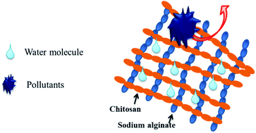
The polyelectrolyte complex (PEC) layer fabricated by chitosan and sodium alginate was anchored on a membrane surface though plasma treatment and layer by layer self-assembly to improve the antifouling properties of the PVDF membrane. The interface properties of modified PVDF membranes were investigated and the results indicated the presence of the PEC layer was conducive to enhance the hydrophilicity and screening ability of the PVDF ultrafiltration membrane due to the hydrophilic crosslinking structure. Furthermore, the fouling resistance including anti-adsorption ability and dynamic antifouling ability for pollutant filtration of modified PVDF membranes were significantly improved due to the anchored PEC layer. For the CS–SA-3 membrane with an assembly number of 3, the adsorption mass of BSA on the membrane surface was only 4 μg cm−2 and the FRR-W values increased to 89%, 99% and 98% for the three typical pollutants of bovine serum albumin, sodium alginate and humic acid, respectively. It was demonstrated that the PEC layer could be used as an antifouling material to improve the antifouling ability of hydrophobic membranes though decreasing the reversible fouling. This article also aimed to provide a simple method to fabricate the antifouling interface.


1. Introduction

Membrane fouling, existing in almost all membrane processes, has become a bottleneck problem for limiting the extensive application of membrane technology,1 especially ultrafiltration (UF) technology used in sewage treatment, the membrane fouling problem is particularly serious and directly affects the service life and application cost of the UF membrane module, so it is urgent to prepare low fouling or non-fouling UF membranes.2–5 Membrane fouling is induced by the adsorption and attachment of pollutants onto the membrane surface and membrane pore surface, the pollutants stranded in the membrane will lead to an irreversible membrane fouling problem.6–8 Thus, the inhibition of initial adsorption and deposition of all kinds of pollutants on the membrane surface and restricting pollutants entering membrane pores to reduce the irreversible fouling ratio are the key factors to prepare UF membranes with antifouling properties.

As for PVDF UF membrane, the pollutants can be adsorbed and accumulated in the areas of membrane surface and pores to cause serious fouling problem by hydrophobic interaction. There are numerous reports about enhancing the antifouling ability of PVDF membrane by blending or surface modification using hydrophilic polymers, zwitterionic polymers, amphiphilic block polymers and nanomaterials to change the hydrophobic properties of effective separation interface.9–12 Polyelectrolyte complexes (PEC), a unique hydrophilic material with distinctive characteristics including strong hydrophilicity, network structure, anti-swelling capacity, simple preparation procedure and extensive source could be prepared by mixing polyanion and polycation electrolyte materials.13–15 Meanwhile, PEC can be used as a kind of potential antifouling material. Firstly, PEC is able to show strong hydrophilicity due to the ion hydration of electrolyte groups, water molecules can be preferentially adsorbed to form hydrated layer with antifouling ability. Secondly, PEC owns strong screening capacity due to the network-like structure, providing obstacles for pollutants entering membrane pores, but there are no negative effect on the water molecules. Finally, the crosslinking of multiple sites enhance the good stability of PEC, which is stable in the flushing process. Thus, the PEC can be used as a functional layer to improve the antifouling capacity of materials interface.

Sodium alginate (SA) and chitosan (CS) are hydrophilic polyanionic and polycationic material, respectively. The segment unit with a large number of ionizable ionic groups and other hydrophilic groups could show excellent adsorption ability to water molecules and form PEC spontaneously though electrostatic interaction.16 In addition, both SA and CS have excellent membrane forming and gelation properties, when they were introduced on material interface, the gelled antifouling coating can be generated to inhibit the adsorption of pollutants and promote the removal of adsorbed pollutants. In this paper, PEC formed by SA and CS was anchored onto PVDF membrane surface though the combination of plasma technology and layer by layer self-assembly (LBL) technology, and the physicochemical properties of the modified membranes surface were characterized though conventional methods including XPS, ATR, CA and SEM, and the antifouling ability of modified membrane for three common pollutants were investigated. This paper aims to propose a simple and efficient method to prepare efficient antifouling material.

2. Experimental

2.1 Materials

Polyvinylidene fluoride (PVDF, MG15) was purchased from Arkema. Chitosan (CS, deacetylation degree was 95%, Mw ∼ 300[thin space (1/6-em)]000). Sodium alginate (SA, Mw ∼ 100[thin space (1/6-em)]000), humic acid (HA, fulvic acid >90%) were purchased from Aladdin. Bovine serum albumin (BSA, 67[thin space (1/6-em)]000 Da), acrylic acid (AA) and polyethylene glycol (PEG, Mw ∼ 10[thin space (1/6-em)]000) were purchased from Sinopharm (China). Dimethylacetamide (DMAC) and acetic acid were AR level.

2.2 Membrane preparation

The neat PVDF membranes were prepared though non-solvent induced phase separation method, PVDF/PEG10000/DMAC (10 g/5 g/50 g) were mixed to prepare the casting solution, pure water was used as the coagulation bath and the casting knife of 300 μm was used to prepare PVDF membranes.

The freeze-dried PVDF membranes were firstly treated with plasma apparatus (CTP-2000K, Nanjing Suman, China) to absorb acrylic acid monomers, and the second time of plasma treatment was employed to fix acrylic acid on membrane surface. The process of plasma treatment were all executed with the power of 100 W for 90 second through dielectric barrier discharge, and the PVDF membrane after plasma treatment was marked as PVDF–PAA. Subsequently, the modified process of LBL self-assembly with CS (2 g L−1) as polyanion and SA (2 g L−1) as polycation were carried out. The specific steps of LBL can be found everywhere,17,18 including assembly process of CS solution and SA solution and cleaning process. An assembled cycle of CS and SA was labeled 1 time. PVDF–AA membranes after assembly of 1 and 3 times were marked as CS–SA and CS–SA-3, respectively.

2.3 Membrane characterization

The surface zeta potential was used for tracking the assembly process and the values of neat and modified PVDF membranes were tested using the nanoparticle size analyzer (DelsaNano, Beckman Coulter, USA) by switching to the test mode of zeta potential. The surface composition of membranes surface were investigated by attenuated total reflectance Fourier transform infrared spectroscopy (ATR-FTIR, Nicolet 8700, USA) and quantified using X-ray photoelectron spectroscopy (XPS, Shimadzu AXIS UltraDLD, Japan) with the take-off angle at 90°. Water contact angles (CA) on the membranes were measured by OCA40Micro (Dataphysics Co. Germany) at room temperature to evaluate the surface wetting ability by testing 10 different positions of each sample. Surface morphology of membranes were viewed with the field emitting scanning electron microscope (SEM, Hitachi SU8010, Japan) and all the samples were coated with gold before observation. The surface roughness of all the membranes were characterized using a Agilent5500 atomic force microscope (AFM, Agilent Technologies Inc., USA) in the tapping mode, the roughness (Rms) values of membranes were characterized with Rq values. The average pore size distribution of the membranes was evaluated by membrane pore size analyzer (GQ/PSMA-10, China). The prepared membrane was immersed in the wetting liquid (n-butanol-rich phase of water–n-butanol) to ensure completely wetted, then the wetting liquid was displaced by displacing liquid (water-rich phase of n-butanol–water) at a certain pressure.

2.4 Separation performance

The separation properties of all membranes were measured using a the dead-end equipment with an effective filtration area of 12.5 cm2, the pressure of filtration cell was supplied by a water pump and all the filtration experiments were carried out at the pressure of 0.1 MPa. The volume of the water permeation was collected for a certain time and the stable flux was calculated by the following eqn (1). The rejection ratio (R) of model pollutant (BSA) was calculated from the concentrations of feed and the permeate via UV spectrophotometer (UV-1800, Shimadzu) according to the following eqn (2), BSA solution (1 g L−1, pH 7.4) was selected as test feed.
 
image file: c5ra08041j-t1.tif(1)
 
image file: c5ra08041j-t2.tif(2)
where J (L m−2 h−1) is the volume of permeated water, t (h) is the permeation time and A (m2) is the effective area for filtration, respectively, C and Cp are the concentrations of BSA in the feed and permeate.

2.5 Fouling test

To evaluate the anti-adsorption capacity of modified membranes, the anti-adsorption ability of the modified membrane surface were evaluated though quantitative analysis with BSA as model protein pollutant. All the tested membranes were cut into regular shape and immersed into BSA (0.5 g L−1, pH 7.4) phosphate buffer solution. After oscillating incubation for 12 h at room temperature to reach adsorption equilibrium, the concentrations of BSA solution before and after adsorption were measured with UV-vis spectrophotometer and the adsorption mass was calculated.

In order to further evaluate the antifouling properties of membranes, BSA, SA and HA were used as three kinds of model pollutants for the filtration fouling, which represented the hydrophobic, hydrophilic and natural contaminants in sewage. The fouled flux recovery ratio (FRR) and the fouled flux recovery ratio after washing (FRR-W) were employed to evaluate the antifouling properties of modified membranes. It should be notice that the membrane with the higher values of FRR and FRR-W indicated the better antifouling properties. The difference of FRR and FRR-W values represented the ratio of irreversible fouling. Pollutants solution were prepared in advance, the BSA solution was prepared by adding 1 g BSA to the phosphate buffer with pH value at 7.4, the SA and HA solution were prepared by adding 1 g SA and 1 g HA to deionized water. The executed filtration process of dynamic fouling consisted of three steps, first of all, stable flux (J) was obtained by pure water filtration, secondly, the feed solution was changed to pollutants solution (BSA, SA and HA) and another stable flux (JP) was obtained, followed, pollutants solution was changed to pure water again and stable flux (J2) was obtained, then a washing process was introduced and the membrane was taken out from the filter system to immerse in the phosphate butter for 10 minutes and rinse with pure water for 10 minutes, when the membrane was reinstalled back into filtration unit, the second water flux (J2w) of pure water was recorded at the end. The FRR, FRR-W were calculated by the eqn (3) and (4), respectively.

 
image file: c5ra08041j-t3.tif(3)
 
image file: c5ra08041j-t4.tif(4)

3. Results and discussion

The modification mechanism and functionalization process of PEC layer being anchored onto PVDF membrane surface were shown in Fig. 1. The neat PVDF membrane is rich in stable C–F and C–C bonds without reactive sites, and the hydrophobic property was not conducive to the adsorption of hydrophilic acrylic monomer. Hydroxyl, amino and the other polar groups could be introduced on the membrane surface and contributed to increase the hydrophilicity to adsorb the acrylic acid monomer by the first plasma treatment. Based on the assist of the second plasma treatment, polyacrylic acid (PAA) or acrylic acid could be directly fixed onto the PVDF membrane surface though the reaction of C[double bond, length as m-dash]C double bond and active radicals of membrane surface, and the PVDF–PAA surface would exhibit negative charge due to the carboxyl group of acrylic acid. The similar method have been reported in the literature about grafting of the polymer monomers containing C[double bond, length as m-dash]C double bond on membrane surface by plasma treatment.19 Followed by the process of LBL self-assembly and the principle of self-assembly could be found everywhere.17 Because PVDF–PAA membrane surface was negatively charged, positively charged chitosan could be assembled onto the membrane surface through electrostatic interaction, and the negatively charged sodium alginate was able to be assembled to the outermost layer of membrane surface subsequently. After several times of LBL assemble, a PEC layer fabricated by CS and SA with crosslinked network structure would cover the membrane surface by electrostatic interaction, which employed positively charged NH3+ and negatively charged COO groups as crosslinking sites. The physical and chemical properties and structure of the modified membrane surface were examined by the followed characterization techniques including surface zeta potential, ATR, XPS, CA, SEM and AFM.
image file: c5ra08041j-f1.tif
Fig. 1 Schematic diagram of the modification process of PVDF membrane (acrylic acid was fixed by plasma treatment, the orange segment and blue segment corresponded to CS and SA polymer, respectively).

Surface zeta potential was used to track the self-assembly process. At different assembly stages, the membrane surface with different polyelectrolyte exhibited changed charge. As shown in Fig. 2, after anchoring AA on membrane surface, the surface potential of PVDF–PAA decreased obviously. With the increasing layer number of LBL, the surface potential of the membrane surface exhibited a sawtooth variation. The outermost layer assembled by CS or SA showed the positive potential and negative potential, respectively. These results perfectly embodied the transformation of the outermost layer materials in assembling process. Furthermore, it could be inferred the introduced polyelectrolyte (CS and SA) would spontaneously form PEC in the self-assembly process based on the static electricity to change the interface characteristics.


image file: c5ra08041j-f2.tif
Fig. 2 Surface zeta potential of modified PVDF membrane with different layer numbers (the neat PVDF noted as 0 layer, PVDF–PAA noted as 0.25 layer, next, the number of layers increases 0.5 after assembling CS one time, and the number of layers increases 1 after assembling a circle of CS/SA).

Fig. 3 showed the ATR spectra of PVDF membranes before and after modification. After using plasma technology to anchor AA on membrane surface, strong new peak at 1716 cm−1 appeared in PVDF–PAA spectrum, which was attributed to C[double bond, length as m-dash]O stretching vibration of the carboxyl group, indicating the AA or PAA had been successfully grafted onto the membrane surface. The negatively charged COOH groups on PVDF–PAA membrane surface could be used as anchoring sites for the followed LBL process. The new peak near 1580 cm−1 appeared in the spectra of CS–SA and CS–SA-3 membranes, which was attributed to the composite peaks of COO and NH3+, including the characteristic vibration of carboxylate of SA and NH bond of CS.20 This peak also proved that CS and SA were anchored on the membrane surface to form the PEC layer by the electrostatic adsorption of COO and NH3+ as the cross-linking site.


image file: c5ra08041j-f3.tif
Fig. 3 ATR-FTIR spectra of neat and modified PVDF membranes.

Table 1 showed the surface element composition of XPS analysis. Obviously, compared to PVDF membranes, the F element of PVDF–PAA membrane surface was reduced and the O and C elements increased, indicating C and O atoms of acrylic acid were fixed onto the membrane surface after plasma treatment, anchored COOH group became active sites for the subsequent modification. With the increasing layer number of LBL, the atomic concentration of F elements were further declined and replaced by the C and O elements on the modified membranes surface, indicating the introduction of self-assembled layers. Furthermore, the N element (>1%) presented in CS–SA and CS–SA-3 membrane surface should belong to the NH2 group of CS, demonstrating CS as polycation existed in the modified PVDF surface, which was the basis for the assembling of SA. The trace N elements in PVDF–PAA should belong to the introduced N-containing polar groups by DBD discharge in air.

Table 1 XPS analysis results of neat and modified PVDF membranes (surface atomic concentration%)
Samples At conc (%)
F C O N
PVDF 35.62 64.15 0.33 0
PVDF–PAA 26.42 66.60 6.87 0.11
CS–SA 18.31 69.57 10.91 1.21
CS–SA-3 9.84 71.41 17.31 1.43


Water contact angle was employed to assess the wetting properties of the neat and modified PVDF membranes. As shown in Fig. 4, PVDF membrane as the hydrophobic material exhibited the highest contact angle of 95°, and the contact angle of PVDF–PAA, CS–SA and CS–SA-3 membrane were 56°, 48° and 45°, respectively. The reduced contact angle of modified PVDF membranes indicated that the wetting properties of the membrane surface were substantially changed due to the introduction of polyelectrolyte PAA, CS and SA. The fabricated hydrophilic PEC by anchored polyelectrolyte would enhance the hydrophilicity of membrane surface and provide the foundation for improve the antifouling performance of PVDF membranes.


image file: c5ra08041j-f4.tif
Fig. 4 Water contact angles of neat and modified PVDF membranes.

According to the SEM images of membrane surface in Fig. 5 and roughness analysis results by AFM in Table 2, the changes in surface topography before and after modification of PVDF membrane was intuitively examined. Obviously, PVDF membrane surface was smooth and there were a lot of membrane pores. After the plasma treatment, PVDF–PAA membrane surface become uneven and the roughness increased to 25.8 nm. After LBL assembly process, the surface of modified CS–SA and CS–SA-3 membranes were covered with a clear film-like material, which should be the PEC layer structure formed by electrostatic assembling due to the excellent film-forming ability of CS and SA. Fig. 6 showed the average pore sizes of the membranes before and after modification. After self-assembly modification, the surface pore size of membrane decreased from the original 16 to 9 nm. In addition, the corresponding Rms of these two membranes increased to 30.8 nm and 45.1 nm, respectively. Although the modified membranes exhibited the increased surface roughness, which might help to improve the hydrophilicity of membrane surface according to the Wenzel equation, and the contact angle confirmed this. From all the above analysis results, it could be demonstrated that PEC layer was anchored to PVDF membrane surface and changed the physical and chemical properties of PVDF membranes interface.


image file: c5ra08041j-f5.tif
Fig. 5 SEM images of neat and modified PVDF membranes.
Table 2 Rms values of neat and modified PVDF membranes (Rq values of AFM analysis)
Samples Rms (5 × 5 μm)
PVDF 16.6 (±2.3)
PVDF–PAA 25.8 (±4.1)
CS–SA 30.8 (±4.7)
CS–SA-3 45.1 (±5.8)


image file: c5ra08041j-f6.tif
Fig. 6 The average pore sizes of neat and modified PVDF membranes.

Fig. 7 showed the separation performance of PVDF membranes before and after modification, it was found that the flux and rejection of the three modified membranes showed a significant trade-off phenomenon. With the increasing layer number of LBL assembly, the water fluxes were reduced and the screening capacity of BSA was reinforced, the rejection of CS–SA-3 membrane was as high as 98%. Compared to the neat PVDF membrane, the increased water flux of PVDF–PAA membrane should be due to the enhanced hydrophilicity by AA and plasma treatment. It was known that the assembled CS and SA on membrane surface were able to spontaneously form PEC, and the increased rejection of CS–SA-3 membrane should result from the screening capacity PEC layer base on the hydrophilic crosslinked structure and the narrowed membrane pores.


image file: c5ra08041j-f7.tif
Fig. 7 Separation performance of neat and modified PVDF membranes.

Anti-adsorption capability was an important parameter for evaluating the fouling resistance of membranes. Due to the hydrophobic interactions, PVDF membrane would absorb a large amount of hydrophobic proteins during separation process and the pollutants would accumulate on the membrane surface and clog the membrane pores, which is the major reason of membrane fouling of PVDF membranes. The anti-adsorption ability of modified PVDF membranes were tested using BSA pollutant, and the results were shown in Fig. 8, the adsorption mass of BSA on neat PVDF membrane was 48 μg cm−2. As a contrast, the modified PVDF membrane exhibited significantly reduced adsorption mass. The adsorption mount of BSA on PVDF–PAA, CS–SA and CS–SA-3 membranes were 26 μg cm−2, 12 μg cm−2 and 4 μg cm−2, it could be learned that the anti-adsorption ability of PVDF membranes was significantly enhanced after anchored PEC on membrane surface. On the one hand, PEC layer could be used as a protective layer structure to decrease the adsorption opportunity of pollutant though preventing BSA from contacting with the hydrophobic surface of PVDF membrane due to the hydrophilic network property. On the other hand, SA as outermost layer of PEC on membrane surface was negatively charged, and BSA also showed a negative charge with the pH value at 7.4, based on the electrostatic repulsion, PEC layer could reject the BSA molecules automatically. Due to the dual role of the protection and repulsion, anti-adsorption capacity of the modified PVDF membranes were able to be significantly improved, the anti-adsorption effect of CS–SA-3 (4 μg cm−2) was better than the reported results in literatures.21,22


image file: c5ra08041j-f8.tif
Fig. 8 The adsorption mass of BSA on the neat and modified PVDF membranes surface.

In order to simulate the fouling problem during filtration, three typical pollutants such as BSA, SA and HA representing hydrophobic protein, hydrophilic polysaccharide and humus three main components of sewage, were selected to investigate the dynamic antifouling ability of modified membranes. The membrane with the higher values of FRR and FRR-W indicated the better antifouling properties, and the difference of FRR and FRR-W values represented the ratio of irreversible fouling. Fig. 9b showed the FRR values of neat and modified PVDF membranes using BSA as pollutant feed solution, it was found that FRR and FRR-W values of the modified PVDF membrane increased significantly. Compared to neat PVDF membranes, the increased amount of PEC on membrane surface (increased layer number of LBL) exhibited the greater FRR and FRR-W values. In addition, it was also found that the difference of FRR values before and after washing was not obvious, indicating irreversible fouling was significantly reduced in membrane fouling. Membrane fouling was affected by multiple factors including hydrophilicity, surface roughness and charge of membrane surface. Excluding the increased roughness, the improved hydrophilicity, negative charge and efficiency rejection of PEC layer endowed the enhanced antifouling ability to BSA. So existed PEC was able to reduce the adsorption and accumulation of pollutants in membrane and enhance the overall fouling resistance of PVDF membrane. The stability of PEC layer is the focus point of paid attention due to the LBL method, the introduced PAA on the membrane surface by plasma treatment was able to strengthen the anchoring effect of PEC layer on membrane surface, the repeated antifouling ability of CS–SA-3 membrane were shown in Fig. 9c, after three times tests of dynamic fouling, FRR values of CS–SA-3 were essentially unchanged, indicating the PEC layer could exert stable antifouling effect without quickly lost.


image file: c5ra08041j-f9.tif
Fig. 9 Filtration fouling of neat and modified PVDF membranes using BSA as pollutant ((a) time-dependent flux variation, 0–60 minute, water, 60–120 min, HA solution, 120–160 min, water, 160–180 min, cleaning process, 180–240 min, water. (b) FRR and FRR-W values, (c) the FRR values of CS–SA-3 membrane for repeated test).

Fig. 10 exhibited the fouling test results using SA as pollutant feed. Obviously, modified PVDF membranes showed the desired FRR-W values, and the FRR-W value of CS–SA-3 membrane was as high as 99%. Furthermore, the significantly difference between FRR-R and FRR values indicated that SA could cause a certain degree of irreversible fouling for modified PVDF membranes due to the characteristics of the SA, SA as the hydrophilic polysaccharide could form cake layer structure easily during filtration, which could be cleaned facilely by water rinsing as reversible fouling. The exhibited high FRR-W values of modified membranes indicated the irreversible fouling in membrane fouling was significantly decreased and the overall antifouling performance of modified membranes was distinctly improved. Fig. 11 showed the fouling test results of HA as pollutant feed. As the assembly process and the amount of PEC on membrane surface increased, modified PVDF membranes also showed the excellent fouling resistance to the natural pollutant with increased FRR and FRR-W values, the FRR-W value of CS–SA-3 membrane reached 98%.


image file: c5ra08041j-f10.tif
Fig. 10 Filtration fouling of neat and modified PVDF membranes using SA as pollutant ((a) time-dependent flux variation, 0–60 minute, water, 60–120 min, HA solution, 120–160 min, water, 160–180 min, cleaning process, 180–240 min, water. (b) FRR and FRR-W values).

image file: c5ra08041j-f11.tif
Fig. 11 Filtration fouling of neat and modified PVDF membranes using HA as pollutant ((a) time-dependent flux variation, 0–60 minute, water, 60–120 min, HA solution, 120–160 min, water, 160–180 min, cleaning process, 180–240 min, water. (b) FRR and FRR-W values).

Fig. 9–11 showed the same tendency about the antifouling performance of modified PVDF membranes for three typical pollutants. The more amount of PEC on membrane surface, the higher the value of FRR-W, so the presence of PEC layer enhanced the antifouling properties of PVDF membranes. PEC was a polyelectrolyte complex with excellent hydrophilicity formed by the assembly of hydrophilic PAA, CS and SA, which provided a basis for the preferentially adsorption of water molecules and exclusion of pollutants. Furthermore, the crosslinked network structure of PEC as a physical barrier, could exhibit strict screening effect to the pollutant with the larger volume and accelerate the permeate of water molecules, the possibility of pollutants entering membrane pores or adhered on membrane surface was greatly reduced, which was conducive to reduce the irreversible fouling. Additionally, a large number of cross-linking sites along polyelectrolyte chain enhanced the stability of PEC to ensure the long-term antifouling effect.

4. Conclusions

PEC layer fabricated by CS and SA was anchored on PVDF membrane surface though plasma treatment and layer by layer self-assembly to improve the antifouling properties. The presence of PEC layer was conducive to enhance the hydrophilicity and screening ability of PVDF membranes. Furthermore, the anti-adsorption ability of modified PVDF membranes was significantly improved, the BSA adsorption mass of CS–SA-3 membrane was only 4 μg cm−2 and the FRR-W values increased to 89%, 99% and 98% for the three typical pollutants of BSA, SA and HA. It was demonstrated that PEC layer could be used as an efficient antifouling material to improve the antifouling property of hydrophobic membranes though decreasing reversible fouling.

Acknowledgements

This work is supported by grants from the Program for New Century Excellent Talents in University (No.NCET-12-0827), Program of Introducing Talents of Discipline to Universities (No. 111-2-04) and Innovation Funds for PhD Students of Donghua University (CUSF-DH-D-2015027).

References

  1. M. A. Shannon, P. W. Bohn, M. Elimelech, J. G. Georgiadis, B. J. Marinas and A. M. Mayes, Nature, 2008, 452, 301 CrossRef CAS PubMed.
  2. P. Le-Clech, V. Chen and T. G. Fane, J. Membr. Sci., 2006, 284, 17 CrossRef CAS PubMed.
  3. K. Kimura, N. Yamato, H. Yamamura and Y. Watanabe, Environ. Sci. Technol., 2005, 39, 6293 CrossRef CAS.
  4. F. Meng, S.-R. Chae, A. Drews, M. Kraume, H.-S. Shin and F. Yang, Water Res., 2009, 43, 1489 CrossRef CAS PubMed.
  5. N. Lee, G. Amy, J.-P. Croué and H. Buisson, Water Res., 2004, 38, 4511 CrossRef CAS PubMed.
  6. J. Wei, G. S. Helm, N. Corner-Walker and X. L. Hou, Desalination, 2006, 192, 252 CrossRef CAS PubMed.
  7. A. Rahimpour, Desalination, 2011, 265, 93 CrossRef CAS PubMed.
  8. N. A. Hamid, A. F. Ismail, T. Matsuura, A. W. Zularisam, W. J. Lau, E. Yuliwati and M. S. Abdullah, Desalination, 2011, 273, 85 CrossRef CAS PubMed.
  9. J. R. Du, S. Peldszus, P. M. Huck and X. Feng, Water Res., 2009, 43, 4559 CrossRef CAS PubMed.
  10. M. Zhang, Q. T. Nguyen and Z. Ping, J. Membr. Sci., 2009, 327, 78 CrossRef CAS PubMed.
  11. Y. C. Chiang, Y. Chang, A. Higuchi, W. Y. Chen and R. C. Ruaan, J. Membr. Sci., 2009, 339, 151 CrossRef CAS PubMed.
  12. S. J. Oh, N. Kim and Y. T. Lee, J. Membr. Sci., 2009, 345, 13 CrossRef CAS PubMed.
  13. Q. Zhao, J. Qian, Q. F. An, Z. Gui, H. Jin and M. Yin, J. Membr. Sci., 2009, 329, 175 CrossRef CAS PubMed.
  14. H. Jin, Q. F. An, Q. Zhao, J. Qian and M. Zhu, J. Membr. Sci., 2010, 347, 183 CrossRef CAS PubMed.
  15. Y. Zhang, J. W. Rhim and X. S. Feng, J. Membr. Sci., 2013, 444, 22 CrossRef CAS PubMed.
  16. I. le Roux, H. M. Krieg, C. A. Yeates and J. C. Breytenbach, J. Membr. Sci., 2005, 248, 127 CrossRef CAS PubMed.
  17. L. Krasemann, A. Toutianoush and B. Tieke, J. Membr. Sci., 2001, 181, 221 CrossRef CAS.
  18. S. A. Sukhishvili, E. Kharlampieva and V. Izumrudov, Macromolecules, 2006, 39, 8873 CrossRef CAS.
  19. Y. Chang, W. J. Chang, Y. J. Shih, T. C. Wei and G. H. Hsiue, ACS Appl. Mater. Interfaces, 2011, 3, 1228 CAS.
  20. S. G. Kim, G. T. Lim, J. Jegal and K. H. Lee, J. Membr. Sci., 2000, 174, 1 CrossRef CAS.
  21. Y. F. Zhao, L. P. Zhu, Z. Yi, B. K. Zhu and Y. Y. Xu, J. Membr. Sci., 2014, 470, 148 CrossRef CAS PubMed.
  22. Y. N. Liu, Y. L. Su, X. T. Zhao, Y. F. Li, R. N. Zhang and Z. Y. Jiang, J. Membr. Sci., 2015, 486, 195 CrossRef CAS PubMed.

This journal is © The Royal Society of Chemistry 2015
Click here to see how this site uses Cookies. View our privacy policy here.