Production of cellulose nanocrystals via a scalable mechanical method

Khairatun Najwa Mohd Aminab, Pratheep Kumar Annamalai*a, Isabel Catherine Morrowcd and Darren Martin*a
aAustralian Institute for Bioengineering and Nanotechnology (AIBN), The University of Queensland, Brisbane, Qld 4072, Australia. E-mail: darren.martin@uq.edu.au; p.annamalai@uq.edu.au
bFaculty of Chemical Engineering & Natural Resources Universiti Malaysia Pahang, Leburaya Tun Razak, 26300 Gambang, Kuantan, Pahang D.M, Malaysia
cARC Centre of Excellence for Functional Nanomaterials, The University of Queensland, Brisbane, Qld 4072, Australia
dAustralian Microscopy and Microanalysis Research Facility, The University of Queensland, Brisbane, Qld 4072, Australia

Received 16th April 2015 , Accepted 25th June 2015

First published on 25th June 2015


Abstract

The production of rigid rod-like cellulose nanocrystals (CNC) via more scalable methods is necessitated by an increasing demand for CNC in various industrial sectors over the last few years. Contemporary protocols involve the consumption of large amounts of strong acids, enzymatic treatments, ultra-sonication and combinations thereof. In an attempt to address this scalability challenge, we aimed to isolate CNC via a scalable mechanical method i.e. high energy bead milling (HEBM). An aqueous dispersion of commercially available microcrystalline cellulose (MCC) was micronized through a HEBM process. This process was optimised by varying the concentration (0.5–2 wt%) and time (15–60 min) parameters, in order to obtain a high yield of well-separated CNCs as characterised by transmission electron microscopy (TEM). Micronisation of cellulose via the HEBM method under mild conditions resulted in cellulose nanocrystals with an average aspect ratio in the range of 20 to 26. The nanocrystals also retained both their crystallinity index (ICr) (85 to 95%) and thermal stability described in terms of onset degradation temperature (Tonset) (230–263 °C). The production yield of CNC from MCC via this process ranged between 57 and 76%. In addition, we found that micronisation of the MCC in the presence of dilute phosphoric acid also resulted in CNC with an average aspect ratio ranging from 21 to 33, high crystallinity (88–90%) and good thermal stability (Tonset 250 °C). In this study, we demonstrate the micronisation of commercially available MCC into CNC and describe their dimensions and properties after acid treatment and HEBM. Furthermore, we are able to recommend the use of this scalable milling process to produce rod-like cellulose nanocrystals having a thermal stability suitable to withstand the melt processing temperatures of most common thermoplastics.

Introduction

Recently, nanoscale cellulose particles have gained much interest from both academia and industry as a new class of renewable nanomaterials due to their useful mechanical properties (e.g. high specific strength and stiffness and thermodimensional stability)1 combined with their nanoscale crystalline and fibrous morphology, chemically tuneable surface functionalities, an ability to be obtained in various dimensions (especially aspect ratio) and renewability.1,2

Depending on the processing methods and the sources, they can be obtained as rod-like low-aspect ratio nanocrystals, filament-like long nanofibrils and sphere-like nanocrystals.2–5 The properties of individual rod-like or rice like cellulose nanocrystals (CNC) are drawing great interest when compared with other engineering materials like aluminium,6–8 steel7 and glass fibre.9 These properties greatly recommend them as advanced reinforcing or functional fillers for thermoplastics, thermosets and elastomers. They have been explored as fillers and rheology modifiers in various fields like thermoplastics,10–12 foams,13 aerogels14 and polymer electrolytes.15,16 Isolation of CNCs via sulphuric acid hydrolysis is not ideal as it requires a considerable consumption of solvent (acid) and time. Furthermore, the resulting product also exhibits poor thermal stability (attributed to the dehydration mechanism facilitated by the sulphate groups)17 and is therefore sometimes unsuitable for further processing at the elevated temperatures (180–250 °C) typically employed in the manufacturing of many thermoplastic polymers. Hence, it becomes critical to produce CNCs with enhanced thermal stability. To date, alternative approaches have included the use of some mild mineral and organic acids18,19 or enzymatic methods in combination with ultrasonic or microwave irradiation.20

Recently, highly thermally stable CNCs have been produced via mild acid hydrolysis (phosphoric acid) and hydrothermal treatment (hydrochloric acid) at laboratory scale.19,21 However, these methods are severely limited by low yields and poor scalability due to the high consumption of mild acids (solvents) and time, respectively.

Mechanical methods have also been explored for the preparation of nanoscale cellulose particles, either as part of the production process using combinations of acid hydrolytic, oxidative, and enzymatic treatments, or directly. These mechanical methods include ultrasonication,20,22 microfluidization,23 high pressure homogenization24 or ball milling.5,25–27 Among these methods, ball milling has many advantages such as the possibility of both dry and wet milling, temperature control and scalability in both batch and continuous formats. For micronising cellulose, wet conditions are preferred as the fluid can create a buffer between bead and cellulose particles thereby minimising the damage to the crystalline structure.25

Recently, ball milling methods have been successfully employed for isolating nanoscale cellulose particles whereby water,28 and organic solvents29 were employed as the milling media resulting in the retention of the inherent crystallinity of the particles. However, most of the mechanical defibrillation methods reported (including wet ball-milling methods), generated a final product of filament like nanofibrils, called nanofibrillated and microfibrillated cellulose (NFC/MFC) or cellulose nanofibres (CNF), which can be characterized with a diameter in nanometers or tens of nanometers and a length of up to several microns.1,30–32

These filament-like nanoparticles have been explored in several applications where fibre entanglements are required. However, in polymer reinforcements, cellulose nanofibrils can raise an issue in terms of dispersibility and viscosity increases in a polymer matrix, especially with an aspect ratio above 100.2

Thus, in this study, we aimed at producing short ‘rod-like’ or ‘rice-like’ cellulose nanocrystals with an aspect ratio below 100 primarily using high-energy bead milling (HEBM) while also investigating various chemical processing conditions.

As shown in Fig. 1(a), HEBM operates via an impact mechanism to micronize the particles. When centrifugal force is generated in the mill, beads are forced to rotate around the mill wall. The reverse rotation of disc also applies centrifugal force in the opposite direction leading to the transition of balls to the opposite walls of mill providing an impact effect to micronize the materials in between the beads.33 Furthermore, HEBM was compared with ultrasonication as one of the mechanical methods explored. As shown in Fig. 1(b), ultra-sonication operates on a well-known high-speed shear mechanism. Upon ultrasonication, high-speed liquid jets are created. These liquid jets pressurize the liquid locally between the particles at high speed (1000 km h−1) to separate or fibrillate them and to promote additional particle collisions, so as to result in very small particles.20


image file: c5ra06862b-f1.tif
Fig. 1 600 dpi in TIF format)[QUESTION MARK]?>(a) High energy bead milling33 and (b) ultrasonication working mechanism. Reproduction of image from (ref. 20) with permission from Elsevier.

By evaluating the resulting dimensions, crystallinity and the properties of CNC produced from both methods, we hereby demonstrate the potential of HEBM to cost-effectively produce CNCs with good thermal stability in a scalable quantity.

Experimental

Materials

Microcrystalline cellulose (MCC) used is Avicel PH-101 (wood based cellulose) (USA, FMC biopolymer corporation). Ortho-phosphoric acid (H3PO4, 85%) from Merck (Australia) was used for HEBM with acid treatment.

Isolation of CNC via ultrasonication

MCC (5 g) was dispersed in 500 ml deionized water and stirred by magnetic bar overnight. The ultrasonication was carried out with an aqueous dispersion of MCC was sonicated using QSonica ultrasonicator for 50 minutes at an output of 500 W, frequency of 20 kHz and amplitude of 20%. Following ultrasonication, the dispersion was stirred for 1 hour and was left in a stationary position for 1 day. At this point two layers of the dispersion were observed with a top layer in consisting of well dispersed CNCs. This top layer was decanted and freeze dried, and this material was designated as CNC-U.

Isolation of CNC via high-energy bead milling

MCC was dispersed in deionized water overnight at various concentrations (0.5–2 wt%). The dispersion was milled using a Laboratory agitator bead mill (LabStar, Netzsch, Germany) with 0.4 mm zirconium beads in a batch process mode, at 1000 rpm for 15, 30 or 60 min. The dispersions obtained were freeze-dried. The resulting CNCs were designated as follows: CNC-MAn where A is MCC concentration (0.5, 1, 2 wt%) and n is milling time (15, 30, 60 min).

To evaluate the effect of mild phosphoric acid on the milling process, MCC was dispersed in dilute 1 wt% H3PO4 for one hour before the milling process. After milling, the CNCs were separated from the liquid by centrifugation. The supernatant was decanted and replaced by an equal amount of deionised water and the mixture was centrifuged again until the supernatant reached neutral pH. Finally the CNCs suspension obtained were freeze-dried. The CNC produced via milling with H3PO4 was coded as CNC-MPAn, where P denotes the acid pre-treatment.

Characterization

Morphology and dimensions. To investigate the structure and the aspect ratio of the CNC preparations, transmission electron microscopy (TEM) was performed. CNCs were suspended in deionized water at a concentration of 0.08 mg ml−1 and the suspension was sonicated for 1 hour. Two microlitres of the suspension was spotted onto a copper–palladium TEM grid. After drying the grids were stained with 2% uranyl acetate and analysed in a JEOL 1011 TEM (JEOL, Japan) at 100 kV, and images were captured on a IS Morada 4K CCD camera system.
Thermal stability analysis. The thermal stability of the CNC variants was determined using thermogravimetric analysis (TGA) under a nitrogen atmosphere. The samples were first heated from room temperature to 110 °C, at a heating rate of 10 °C min−1, isothermally held for 10 min and further heated to 500 °C at a heating rate 5 °C min−1.
ICP-OES analysis. ICP-OES analysis was used to determine the presence of the element zirconia contained in CNCs samples. The analysis was performed to identify the presence of any metal elements in the sample as zirconia balls were used in the milling process.
Crystallinity. The degree of crystallinity of CNCs was examined by X-ray diffraction (XRD). XRD was generated at 40 kV using a current of 40 mA. The crystallinity index of CNCs was determined by the XRD peak height method. The crystallinity index is calculated using the following equation:
 
image file: c5ra06862b-t1.tif(1)
where I002 is the maximum intensity of the peak corresponding to plane having the miller indices 002 and Iam is the minimal intensity of diffraction of the amorphous phase at 2θ = 18°.34
Dispersion studies. The dispersibility of CNC was investigated by dispersing the CNCs in deionised water. The dispersions were prepared at concentration of 2 mg ml−1 and sonicated using water bath sonicators for 4 hours. Pictures were taken immediately after preparation and subsequently after 1 hour, 1 day and 2 days.
Zeta potential. The zeta (ζ) potentials of the CNCs were measured at a concentration of 0.01 mg ml−1 with a Zetasizer analyzer. Deionised water was used as a dispersant. The ζ potential was calculated by use of the Smoluchowski equation.

Results and discussion

Morphology and dimension

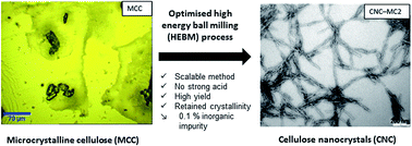
Transmission electron microscopy (TEM) was carried out to investigate the dimensions and structural morphology of CNCs. The dimensions were measured using ImageJ software by magnifying the images to identify the rice-like particles end to end with at least 10 particles measured. From the TEM images in Fig. 2 and 3, it can be seen that MCC was successfully fibrillated and deconstructed into nanocrystals via the HEBM process.
image file: c5ra06862b-f2.tif
Fig. 2 Optical microscopic image (top left) of microcrystalline cellulose (MCC) before milling and TEM images of CNCs obtained via HEBM from the dispersion of 0.5 wt% MCC in deionized water.

image file: c5ra06862b-f3.tif
Fig. 3 TEM images of CNCs obtained via HEBM from the dispersion of 1 wt% (left) and 2 wt% (right) of MCC obtained via HEBM process and via ultrasonication (bottom).

Unlike other mechanical processes30 reported, including a – similar ball milling process35 (with softwood pulp sheet and alkaline solutions) where only micro- and nano-fibrillated cellulose (MFC/NFC) were observed. Here, the nanoparticles produced via our HEBM investigation exhibited rod-like or long rice-like morphology. As listed in Table 1, the aspect ratio of CNC products ranged from 20 to 26. Interestingly, the morphology and the aspect ratio values are actually quite similar to that of the CNCs produced via acid hydrolysis.36,37 Furthermore, we found that the changes to morphology and dimensions were not significantly affected by the duration of milling (between 15 and 120 min) and the concentration (between 0.5 and 2 wt%) of the suspension used in this study. It implies that even at 15 minutes of milling, rod-like cellulose nanocrystals can be obtained. However, according to the TEM images, the interaction between the individual CNCs is slightly altered, for example, the CNCs obtained from higher concentrations (e.g. 2 wt%) tend to interact through edges of the particles indicating the electrostatic interactions between the CNCs. The production yield (%) (product weight over raw material weight) of CNCs from the suspension of MCC ranged between 57 and 76%. It is to be noted that some yield reduction can be attributed to material losses occurring during handling, including withdrawal of the suspension from the mill, and filtering plus washing of the balls after the milling process. The yield% values are relatively higher than the reported yield of CNCs obtained via acid hydrolysis (22–52%) depending on sources.36,38–40

Table 1 Dimensions and the production yield of CNCs isolated using high energy bead milling
Sample Conc. (wt%) Milling time (min) Length (nm) Width (nm) Aspect ratio Yield (%)
CNC-MA1 0.5 15 320 ± 53 15 ± 3 21 69
CNC-MA2 0.5 30 351 ± 90 18 ± 5 20 57
CNC-MA3 0.5 60 317 ± 63 18 ± 4 23 65
CNC-MB1 1 15 286 ± 100 13 ± 5 23 64
CNC-MB2 1 30 301 ± 115 13 ± 7 24 66
CNC-MB3 1 60 371 ± 71 14 ± 5 26 76
CNC-MC1 2 15 431 ± 138 20 ± 9 23 67
CNC-MC2 2 30 387 ± 83 15 ± 3 26 58
CNC-MC3 2 60 424 ± 90 17 ± 4 25 76


As a comparison, CNC was also obtained via an ultrasonication method following previously reported protocols20,22 with some slight modifications. Fig. 4 shows the TEM images of CNCs obtained from the top layer of the suspension obtained after ultra-sonication (CNC-U) of the MCC. They also showed ‘rod-like’ or ‘rice-like’ nanocrystals with an average aspect ratio of 15 (165 ± 23 nm length and 11 ± 2 nm in width). However, the production yield (%) of CNC from top layer suspension was very low, i.e. 8–10% of the initial weight. Meanwhile, the bottom layer had clusters or agglomerates of cellulose particles with dimensions of 100 nm to 500 nm (Fig. S1 in ESI).


image file: c5ra06862b-f4.tif
Fig. 4 TGA thermograms of CNC obtained via (a) HEBM and (b) ultrasonication obtained from MCC, retainment of thermal stability.

Thermal stability

Thermal stability of CNCs obtained via milling was measured by thermogravimetric analysis (TGA). Fig. 4 compares the thermograms of MCCs and CNCs. A slight weight loss at a low temperature region (<110 °C) can be attributed to the residual water in the cellulose particles even after vacuum drying.

The onset degradation temperature (Tonset) for MCC was 270 °C, whereas a slight decrease in Tonset was observed for CNCs (230–263 °C) obtained after the milling process. This slight decrease can be attributed to either the increase in the surface area, fragmentation or decrease in crystallinity caused by the milling process.

The degradation of CNC-U starts from 250 °C which is slightly lower than the onset degradation temperature of MCC. This decrease may be associated with the increase in free cellulose chains and fragmentations brought about by ultrasonication.19 The CNCs obtained via HEBM process show higher thermal stability when compared to the thermal stability of the CNCs obtained via typical sulphuric acid hydrolysis. These start to decompose at 150 °C.19,41 It is to be noted that the processing temperature of many thermoplastic polymers falls within the range of thermal stability exhibited by CNCs obtained via HEBM process.

Crystallinity of CNC

The effect of milling on the crystalline structure of MCC particles was investigated by X-ray diffraction analysis. The characteristic peaks at 2θ = 15 (101), 16.5 (10[1 with combining macron]), 20.8 (021), 22.5 (002) and 34.3 (040) of crystalline polymorph I cellulose for MCC42 can be seen in Fig. 5. These peaks can be still observed for the CNCs obtained via milling process. The μ crystallinity index (ICr) expressed as a percentage was calculated from the ratio of the crystalline peak (I002Iam) and the total peak of 002 lattice plane. The ICr of the initial MCC was about ∼95%.
image file: c5ra06862b-f5.tif
Fig. 5 XRD patterns of commercial MCC and CNCs obtained (after 60 min of milling) via HEBM method showing the retainment of crystalline domains of cellulose at 2θ = 15 (101), 16.5 (10[1 with combining macron]), 20.8 (021), 22.5 (002) and 34.3 (040).

CNCs obtained by the milling process showed a degree of crystallinity in the range between 85–95% (Table 2) with no significant trend observed upon varying concentration (0.5–2 wt%) and milling time (15–60 min). The crystallinity for CNC obtained via ultrasonication was within this range, ∼90%, indicating a similar crystalline structure. The crystallinity range observed in this study is still higher than the earlier reported values (67–82%) for CNCs obtained via acid hydrolysis.5,19 It is also higher than the crystallinity (∼32%) reported for CNC obtained after prolonged dry milling (1–6 days) and dilute acid hydrolysis.43 Nevertheless, the maximum milling time was only 60 minutes via the wet milling conditions used in this study lead to less destruction of the crystal structure than seen with extensive dry milling.

Table 2 Crystallinity (%), zeta potential (mV) of CNCs obtained via HEBM method and the zirconium amount (ppm) present in the freeze dried CNC as obtained from ICPOES analysis
Feed concentration (wt%) Duration of milling (min) Crystallinity (%) Zeta potential (mV) Zirconium amount (ppm)
0.5 15 92.6 −35.0 689
30 91.5 −42.5 1164
60 89.7 −41.0 1830
1.0 15 87.8 −31.0 417
30 95.3 −31.4 1528
60 91.0 −33.6 1449
2.0 15 94.6 −28.0 746
30 92.9 −41.6 133
60 85.9 −40.0 389


Stability and zeta potential of suspension

As mentioned earlier, dispersibility is one of the key properties required for suitability as a reinforcing filler, as this property determines the ability to form stable colloidal suspensions.44,45

Espinosa et al.19 has discussed how CNCs dispersibility strongly depends on their aspect ratio and the ability of the solvent and surface groups to counterbalance the attractive hydrogen-bond interactions exerted by the abundant hydroxyl groups. In the case of CNCs that have been hydrolysed with sulphuric acid, they are known to have good aqueous dispersibility due to sulphate (SO42−) groups on the surface of particles.46,47

The suspensions obtained after milling are stable even after several weeks (Fig. S2) unlike the suspension obtained via ultra-sonication (Fig. S1(a)), where rapid separation into two layers was observed.

However, freeze-drying affected the dispersibility of the CNC produced via HEBM (Fig. S3). Further characterisation of dispersibility, was carried out by measuring the zeta potential of this CNC. As visual examination suggested, CNC dispersions had settled down after 2 days and the ζ potential recorded a value within the range of −28 and −42 mV (Table 2) indicating that HEBM CNCs are fairly stable in water and can be considered stable as compared to CNC produced via acid hydrolysis. For typical CNC obtained from sulphuric acid hydrolysis, a zeta potential of −95 mV has been achieved due to sulphate charges which can be considered excellent stability.48,49 As zirconia beads are used in the milling process, it was also necessary to know the purity of CNC preparation or the extent of metal ion contamination of the milled CNCs. The result obtained from ICP-OES analysis showed a trace of metal ions including the zirconium (Zr) (Table 2). Nevertheless, the values of ‘Zr’ did not follow any particular trend with either concentration or duration of milling.

Efficiency of CNC production from MCC via HEBM process

The preparation of CNC from commercially available MCC has been already reported by both acid hydrolysis and mechanical shear methods for nanocomposite preparation. A typical acid hydrolysis protocol involves the hydrolysis at higher temperature, with 64% sulfuric acid, multiple dilutions and centrifugations and several days of dialysis and ultra-sonication.36 Table 3 provides the data (conditions and yield) obtained from published literature regarding the isolation of CNC from MCC via acid hydrolysis, where the solid to liquid ratio refers the weight of MCC over volume of 64% acid solution used during hydrolysis. In comparison, HEBM process mainly requires the deionised water as media with a solid-to-liquid ratio of 1[thin space (1/6-em)]:[thin space (1/6-em)]200, 1[thin space (1/6-em)]:[thin space (1/6-em)]100 and/or 1[thin space (1/6-em)]:[thin space (1/6-em)]50.
Table 3 Acid hydrolysis conditions reported for isolating of CNC from MCC using sulphuric acid
Solid to liquid ratio Reaction time (h) Temperature (°C) Yield (%) Ref.
1[thin space (1/6-em)]:[thin space (1/6-em)]8.75 2 45 50 and 51
5 45 21 52
5 45 32 53
1[thin space (1/6-em)]:[thin space (1/6-em)]10 2 44 30 54
2 45 30 36 and 55
1[thin space (1/6-em)]:[thin space (1/6-em)]17.5 1 45 20 56 and 57
3 45 58 and 59


It can be noted that the hydrolysis of MCC with 64% sulphuric acid in a typical solid-to-liquid ratio of 1[thin space (1/6-em)]:[thin space (1/6-em)]10, the production yield of CNC is ∼30% with reference to the initial material input. On the other hand, HEBM process of MCC in deionised water with a solid-to-liquid ratio of 1[thin space (1/6-em)]:[thin space (1/6-em)]50, yielded about 58–76% of CNC. Table 4 compares the time, energy consumption and the production yield based on a typical lab-scale acid hydrolysis protocol35 and the batch-milling process (see the ESI Table S1). It can be apparently evident that for the production of one kilogram of CNC via acid hydrolysis process, it requires two or threefold of raw material (MCC) and higher energy and longer time in comparison with that via an optimised HEBM process.

Table 4 Comparison of CNC production via HEBM process and a typical acid hydrolysis process36
Parameters HEBM process Acid hydrolysis
Product yield (%) 76 30
Initial weight of MCC (g) 4 5
Acid consumption (L) 31
Time (days) 1 6
Energy (MJ) 12 29


Influence of mild acid treatment

In order to obtain CNCs with improved thermal stability and dispersibility, the milling was also performed with a mild acid (phosphoric acid). The MCC dispersions (0.5 and 2 wt%) were milled with 1 wt% of phosphoric acid (H3PO4) at 15, 30 and 60 minutes of milling time. Fig. 6 shows the TEM images and TGA thermograms of CNC obtained by this process from 0.5 wt%. The aspect ratio of the CNCs obtained via milling with dilute phosphoric acid was higher than the CNCs obtained from milling without H3PO4. As can be seen in Table 5, their length and width ranged between 200 and 400 nm and 7 to 18 nm, respectively. Conversely, the remaining samples did not show distinctive shapes (Fig. S4) and thus it was not possible to measure the exact dimensions of these particles. This may be presumably due to the surface swelling or dissolution by phosphoric acid depending on residence time.60 With suspension of 0.5 wt% concentration, the milling for longer times (above 30 min) showed agglomeration (Fig. S4). Compared to CNC-MC3 (Fig. 3) and CNC-MPC3 (Fig. 6), suggesting that with increasing concentration of cellulose, HEBM in presence of dilute H3PO4 may facilitate the surface swelling and agglomeration of CNC particles. However, milling with dilute H3PO4 has relatively improved the thermal stability when compared to CNCs milled without phosphoric acid; for example, the onset degradation temperature was increased to approximately 250 °C. Furthermore, the cellulose I polymorph-crystalline structure was also unaffected in the preparation (Fig. S6).
image file: c5ra06862b-f6.tif
Fig. 6 TEM images of CNC produced by HEBM with phosphoric acid and Thermogravimetric analysis (TGA) curves.
Table 5 Dimension and the production yield of CNCs isolated using HEBM with dilute phosphoric acid
Sample Length (nm) Width (nm) Aspect ratio Yield (%)
CNC-MPA1 230 ± 61 8 ± 2 33 71
CNC-MPA2 401 ± 94 19 ± 4 21 59


The stability of the suspension obtained from the freeze-dried CNCs obtained via milling with H3PO4 was also studied (Fig. S5). Our results show that a few phosphate groups ((PO4)3−) might possibility attach to the surface of the cellulose structure and function as a stabilizing agent, as the amount of acid used was low. In fact, H3PO4 is likely to have assisted in the isolation process. However, CNCs milled with phosphoric acid recorded ζ potential between −23 to −38 mV (Table 6) showing that the CNCs have moderate stability, similar to the CNC produced via HEBM without this acid.

Table 6 Crystallinity and zeta potential of CNC obtained via HEBM process with dilute phosphoric acid
Feed concentration (wt%) Duration of milling (min) Amount of zirconium (ppm) Crystallinity (%) Zeta potential (mV)
0.5 15 219 88 −23.0
  30 373 88 −22.9
2.0 60 550 90 −37.5


Table 6 also summarises the physicochemical properties of the CNCs obtained via milling with dilute phosphoric acid. The degree of crystallinity of these CNC-MPA1 and CNC-MPC3 was between 88 and 90% indicating the crystalline structure of cellulose was not strongly affected by milling with dilute H3PO4 for short periods (Fig. S6). Traces of Zr ions were also detected in the suspension.

Conclusions

Isolation of cellulose nanocrystals was successfully carried out using a high energy ball milling method with and without the aid of dilute phosphoric acid. CNCs produced by this method showed distinctive rod-like or rice-like morphology with an average aspect ratio ranging between 20 and 26. The nanocrystals produced have the appropriate characteristics for reinforcing thermoplastic polymers as the higher surface area will increase the interaction between the filler and the polymer matrix. Furthermore, with the degree of crystallinity obtained, in the range of 85 to 95%, this shows a good preservation of cellulose I crystal structure which is also important in transferring the mechanical properties required in nanocomposite applications. Moreover, the thermal properties of HEBM CNCs also recorded high thermal stability values, with onset degradation temperatures of between 230–263 °C, thereby enabling them be used in thermoplastic manufacturing i.e. melt compounding or reactive extrusion, which usually involves high temperature processing. In comparison of acid hydrolysis, the HEBM process significantly shows the low energy and time consumption and no/minimal use of strong acids for the production CNCs in high yield. Production of CNCs. Using the HEBM process, CNCs can be produced with a high level of scalability suggesting this method should be further explored to fulfil the industrial demand for CNCs in various applications like surface coatings, adhesives, thermoplastic manufacturing etc.

Acknowledgements

The authors gratefully acknowledge the facilities as well as the scientific and technical assistance of the Centre for Microscopy and Microanalysis (CMM), University of Queensland. KNMA also acknowledges the financial support from Ministry of Education, Malaysia and University Malaysia Pahang, Malaysia.

Notes and references

  1. R. J. Moon, A. Martini, J. Nairn, J. Simonsen and J. Youngblood, Chem. Soc. Rev., 2011, 40, 3941–3994 RSC .
  2. S. J. Eichhorn, A. Dufresne, M. Aranguren, N. E. Marcovich, J. R. Capadona, S. J. Rowan, C. Weder, W. Thielemans, M. Roman, S. Renneckar, W. Gindl, S. Veigel, J. Keckes, H. Yano, K. Abe, M. Nogi, A. N. Nakagaito, A. Mangalam, J. Simonsen, A. S. Benight, A. Bismarck, L. A. Berglund and T. Peijs, J. Mater. Sci., 2010, 45, 1–33 CrossRef CAS PubMed .
  3. P. K. Annamalai, K. L. Dagnon, S. Monemian, E. J. Foster, S. J. Rowan and C. Weder, ACS Appl. Mater. Interfaces, 2014, 6, 967–976 CAS .
  4. M. Adsul, S. K. Soni, S. K. Bhargava and V. Bansal, Biomacromolecules, 2012, 13, 2890–2895 CrossRef CAS PubMed .
  5. D. Yang, X.-W. Peng, L.-X. Zhong, X.-F. Cao, W. Chen and R.-C. Sun, Cellulose, 2013, 20, 2427–2437 CrossRef CAS PubMed .
  6. J. F. Shackelford, ed. J. F. Shackelford and W. Alexander, Materials Science and Engineering Handbook, CRC Press, 2000 Search PubMed.
  7. P. Soroushian, A. M. ASCE and K.-B. Choi, Journal of Structural Engineering, 1987, 113, 663–672 CrossRef .
  8. B. Noble, J. Harris and K. Dinsdale, J. Mater. Sci., 1982, 17, 461–468 CrossRef CAS .
  9. P. Wambua, J. Ivens and I. Verpoest, Compos. Sci. Technol., 2003, 63, 1259–1264 CrossRef CAS .
  10. J. Mendez, P. K. Annamalai, S. J. Eichhorn, R. Rusli, S. J. Rowan, E. J. Foster and C. Weder, Macromolecules, 2011, 44, 6827–6835 CrossRef CAS .
  11. K. Shanmuganathan, J. R. Capadona, S. J. Rowan and C. Weder, J. Mater. Chem., 2010, 20, 180–186 RSC .
  12. K. Ben Azouz, E. C. Ramires, W. van den Fonteyne, N. El Kissi and A. Dufresne, ACS Macro Lett., 2012, 1, 236–240 CrossRef CAS .
  13. A. J. Svagan, L. A. Berglund and P. Jensen, ACS Appl. Mater. Interfaces, 2011, 3, 1411–1417 CAS .
  14. G. Hayase, K. Kanamori, K. Abe, H. Yano, A. Maeno, H. Kaji and K. Nakanishi, ACS Appl. Mater. Interfaces, 2014, 6, 9466–9471 CAS .
  15. M. A. S. A. Samir, F. Alloin, W. Gorecki, J.-Y. Sanchez and A. Dufresne, J. Phys. Chem. B, 2004, 108, 10845–10852 CrossRef CAS .
  16. E. D. Cranston and D. G. Gray, Biomacromolecules, 2006, 7, 2522–2530 CrossRef CAS PubMed .
  17. N. Wang, E. Y. Ding and R. S. Cheng, Polymer, 2007, 48, 3486–3493 CrossRef CAS PubMed .
  18. B. Braun and J. R. Dorgan, Biomacromolecules, 2009, 10, 334–341 CrossRef CAS PubMed .
  19. S. Camarero Espinosa, T. Kuhnt, E. J. Foster and C. Weder, Biomacromolecules, 2013, 14, 1223–1230 CrossRef CAS PubMed .
  20. W. Li, J. Yue and S. Liu, Ultrason. Sonochem., 2012, 19, 479–485 CrossRef CAS PubMed .
  21. H. Yu, Z. Qin, B. Liang, N. Liu, Z. Zhou and L. Chen, J. Mater. Chem. A, 2013, 1, 3938 CAS .
  22. Q. Cheng, S. Wang and T. G. Rials, Composites, Part A, 2009, 40, 218–224 CrossRef PubMed .
  23. T. Zimmermann, N. Bordeanu and E. Strub, Carbohydr. Polym., 2010, 79, 1086–1093 CrossRef CAS PubMed .
  24. M. Paakko, M. Ankerfors, H. Kosonen, A. Nykanen, S. Ahola, M. Osterberg, J. Ruokolainen, J. Laine, P. T. Larsson, O. Ikkala and T. Lindstrom, Biomacromolecules, 2007, 8, 1934–1941 CrossRef CAS PubMed .
  25. C. C. Kwan, M. Ghadiri, D. G. Papadopoulos and A. C. Bentham, Chem. Eng. Technol., 2003, 26, 185–190 CrossRef CAS PubMed .
  26. Y. Yu and H. Wu, AIChE J., 2011, 57, 793–800 CrossRef CAS PubMed .
  27. V. Baheti and J. Militky, Fibers Polym., 2013, 14, 133–137 CrossRef CAS PubMed .
  28. L. Y. Zhang, T. Tsuzuki and X. G. Wang, Mater. Sci. Forum, 2010, 654–656, 1760–1763 CrossRef CAS .
  29. P. Huang, M. Wu, S. Kuga, D. Wang, D. Wu and Y. Huang, ChemSusChem, 2012, 5, 2319–2322 CrossRef CAS PubMed .
  30. H. Charreau, M. L. Foresti and A. Vazquez, Recent Pat. Nanotechnol., 2013, 7, 56–80 CrossRef CAS .
  31. N. Amiralian, P. K. Annamalai, P. Memmott, S. Schmidt, E. Taran and D. Martin, RSC Adv., 2015, 5, 32124–32132 RSC .
  32. N. Amiralian, P. K. Annamalai, P. Memmott and D. Martin, Cellulose, 2015 DOI:10.1007/s10570-015-0688-x .
  33. V. K. Baheti, R. Abbasi and J. Militky, World J. Eng., 2012, 9, 45–50 CrossRef CAS PubMed .
  34. R. M. Sheltami, I. Abdullah, I. Ahmad, A. Dufresne and H. Kargarzadeh, Carbohydr. Polym., 2012, 88, 772–779 CrossRef CAS PubMed .
  35. L. Zhang, T. Tsuzuki and X. Wang, Cellulose, 2015, 22, 1729–1741 CrossRef CAS PubMed .
  36. D. Bondeson, A. Mathew and K. Oksman, Cellulose, 2006, 13, 171–180 CrossRef CAS PubMed .
  37. X. M. Dong, J.-F. Revol and D. G. Gray, Cellulose, 1998, 5, 19–32 CrossRef CAS .
  38. J.-W. Rhim, J. P. Reddy and X. Luo, Cellulose, 2014, 22, 407–420 CrossRef .
  39. W. Y. Hamad and T. Q. Hu, Can. J. Chem. Eng., 2010, 88, 392–402 CAS .
  40. P. Satyamurthy, P. Jain, R. H. Balasubramanya and N. Vigneshwaran, Carbohydr. Polym., 2011, 83, 122–129 CrossRef CAS PubMed .
  41. M. Roman and W. T. Winter, Biomacromolecules, 2004, 5, 1671–1677 CrossRef CAS PubMed .
  42. S. Park, J. O. Baker, M. E. Himmel, P. A. Parilla and D. K. Johnson, Biotechnol. Biofuels, 2010, 3, 10 CrossRef PubMed .
  43. H. Zhao, J. H. Kwak, Y. Wang, J. A. Franz, J. M. White and J. E. Holladay, Energy Fuels, 2006, 20, 807–811 CrossRef CAS .
  44. R. H. Marchessault, F. F. Morehead and N. M. Walter, Nature, 1959, 184, 632–633 CrossRef CAS PubMed .
  45. B. G. Ranby, Discuss. Faraday Soc., 1951, 11, 158–164 RSC .
  46. S. Mueller, C. Weder and E. J. Foster, RSC Adv., 2014, 4, 907 RSC .
  47. H. A. Silvério, W. P. Flauzino Neto, N. O. Dantas and D. Pasquini, Ind. Crops Prod., 2013, 44, 427–436 CrossRef PubMed .
  48. H. Kargarzadeh, I. Ahmad, I. Abdullah, A. Dufresne, S. Y. Zainudin and R. M. Sheltami, Cellulose, 2012, 19, 855–866 CrossRef CAS .
  49. Y. Boluk, R. Lahiji, L. Y. Zhao and M. T. McDermott, Colloids Surf., A, 2011, 377, 297–303 CrossRef CAS PubMed .
  50. M. L. Auad, M. A. Mosiewicki, T. Richardson, M. I. Aranguren and N. E. Marcovich, J. Appl. Polym. Sci., 2010, 115, 1215–1225 CrossRef CAS PubMed .
  51. N. E. Marcovich, M. L. Auad, N. E. Bellesi, S. R. Nutt and M. I. Aranguren, J. Mater. Res., 2006, 21, 870–881 CrossRef CAS .
  52. W. Bai, J. Holbery and K. C. Li, Cellulose, 2009, 16, 455–465 CrossRef CAS PubMed .
  53. I. Capron and B. Cathala, Biomacromolecules, 2013, 14, 291–296 CrossRef CAS PubMed .
  54. L. Petersson, I. Kvien and K. Oksman, Compos. Sci. Technol., 2007, 67, 2535–2544 CrossRef CAS PubMed .
  55. I. Kvien, B. S. Tanem and K. Oksman, Biomacromolecules, 2005, 6, 3160–3165 CrossRef CAS PubMed .
  56. E. Fortunati, I. Armentano, Q. Zhou, A. Iannoni, E. Saino, L. Visai, L. A. Berglund and J. M. Kenny, Carbohydr. Polym., 2012, 87, 1596–1605 CrossRef CAS PubMed .
  57. E. Fortunati, M. Peltzer, I. Armentano, L. Torre, A. Jimenez and J. M. Kenny, Carbohydr. Polym., 2012, 90, 948–956 CrossRef CAS PubMed .
  58. D. G. Liu, X. Y. Chen, Y. Y. Yue, M. D. Chen and Q. L. Wu, Carbohydr. Polym., 2011, 84, 316–322 CrossRef CAS PubMed .
  59. H. Y. Liu, D. G. Liu, F. Yao and Q. L. Wu, Bioresour. Technol., 2010, 101, 5685–5692 CrossRef CAS PubMed .
  60. J. Zhang, J. Zhang, L. Lin, T. Chen, J. Zhang, S. Liu, Z. Li and P. Ouyang, Molecules, 2009, 14, 5027–5041 CrossRef CAS PubMed .

Footnote

Electronic supplementary information (ESI) available. See DOI: 10.1039/c5ra06862b

This journal is © The Royal Society of Chemistry 2015
Click here to see how this site uses Cookies. View our privacy policy here.