A novel lithium–sulfur battery cathode from butadiene rubber-caged sulfur-rich polymeric composites

Bin Zhanga, Shuanjin Wanga, Min Xiaoa, Dongmei Han*a, Shuqin Songa, Guohua Chenb and Yuezhong Meng*a
aThe Key Laboratory of Low-carbon Chemistry & Energy Conservation of Guangdong Province/State Key Laboratory of Optoelectronic Materials and Technologies, SunYat-sen University, Guangzhou 510275, P. R. China. E-mail: mengyzh@mail.sysu.edu.cn; handongm@mail.sysu.edu.cn; Fax: +86 20 84114113; Tel: +86 20 84114113
bDepartment of Chemical Engineering, Hong Kong University of Science & Technology, Hong Kong, P. R. China

Received 16th April 2015 , Accepted 21st April 2015

First published on 22nd April 2015


Abstract

Novel sulfur-rich polymeric materials were readily prepared via facile solution vulcanization of the commercial butadiene rubber (BR) and sulfur element, and were investigated as cathode materials for lithium–sulfur batteries. During the solution vulcanization procedure, the double bonds (C[double bond, length as m-dash]C) in butadiene rubber are chemically cross-linked with sulfur. Moreover, the sulfur canalso self-polymerize into polymeric sulfur with long molecular chain. The polymeric sulfur chains penetrate into the cross-linked BR network to form a unique semi-internal penetration network (semi-IPN) confinement structure, which can effectively alleviate the dissolution and diffusion of intermediate polysulfide into electrolytes. Meanwhile, the obtained sulfur-rich polymeric composites have high sulfur contents even over 90%. As a result, the as-prepared sulfur-rich polymeric composites (BR-SPC) with network confine caged structure exhibit excellent cycling stability and high coulombic efficiency. An initial discharge specific capacity of 811 mA h g−1 is reached, and retains 671 mA h g−1 after 50 cycles at 0.1 C. The capacity retention rate and coulombic efficiency are 83%, 100%, respectively. Additionally, Super P (carbon black) was added in situ before vulcanization to increase the conductivity of BR-SPC composites. The BR-SPC composite containing Super P (BR-SPC-SP) reveals higher capacity retention of 85% over 50 cycles at 0.5 C than the BR-SPC composite without Super P.

1. Introduction

Over the last three decades, lithium–sulfur secondary batteries have attracted significant interest because elemental sulfur has a theoretical capacity 1672 mA h g−1 and a specific energy of 2600 W h kg−1, which is at least ten times greater than that of commercially used transition-metal phosphates and oxides.1,2 As a cathode, sulfur is able to host two lithium ions nontopotactically, described by the reaction S8 + 16Li = 8Li2S, which lies ∼2.2 V with respect to Li+/Li.3 Sulfur also has other advantages, such as low safety concerns/environmental footprint, very high natural abundance, and competitivecost.4–6 For these reasons, sulfur has been studied extensively as a cathode material, and lithium–sulfur batteries have been considered as one of the most promising candidates for the next generation of high energy batteries.7,8 However, there are a few key challenges for the lithium–sulfur battery system so far, which have greatly limited the practical applications of lithium–sulfur batteries.9 First, sulfur is electrochemically inactive due to a poor intrinsic conductivity (5 × 10⁻³⁰ S cm−1 at 25 °C), leading to a low utilization rate of active material within theelectrodes.10,11 Second, the polysulfide ions that are formed during charge and discharge processes are highly soluble. The dissolved intermediate polysulfide (Li2Sx, 3 ≤ x ≤ 8) can diffuse through electrolytes to the Li metal anode and is reduced therein to solid precipitates in the form of Li2SorLi2S2.12 These low-order polysulfides can also travel back to the cathode during cycling. This shuttle-like travelling issue results in the loss of active materials, capacity fade, low coulombic efficiency, corrosion of the lithium anode, and self-discharge.12,13 Third, the large volume change of the cathode during cycling may trigger the separation of active materials from the cathode and the collapse of the cathode structure, accelerating the capacity decay of lithium–sulfur batteries.8,14,15

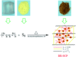
To meet the aforementioned challenges, various strategies have been explored, such as the optimizations of the electrolytes, the modifications of the cathode materials, the novel structural design of the electrode, and the protection of Li anode.16–19 Among them, two major approaches have been conducted to modify the cathode materials. One is to stop or alleviate the dissolution and shuttle of the intermediate polysulfide (Li2Sx, 3 ≤ x ≤ 8) in the liquid electrolyte via some physical methods. For instance, sulfur was wrapped into some conductive host matrixes (carbon materials or polymers) by means of coating or encapsulating techniques.20–23 The other is fixing sulfur atoms into long polymer chains through some chemical methods to prevent active materials from losing. Beyond that, random coil of the polymer chains also plays a role in alleviating the loss of active materials and shuttle of the intermediate polysulfide. Some researchers had successively employed sulfur-contained polymer as the cathode material. Conductive polyacrylonitrile-based sulfur-containing heterocyclic compounds were prepared to use as the cathode material for lithium–sulfur batteries in Wang J L's group.24 Its initial discharge capacity was up to 850 mA h g−1, and remained above 600 mA h g−1 after 50 cycles. Thereafter, Michael's group also prepared a sulfur–polyacrylonitrile composite, and the specific capacity of the obtained cell was 370 mA h g−1 polymer after 40 cycles when LiPF6 in carbonate solvent was used as the electrolyte.25 A novel conductive sulfur–polypyrrole composite material was reported by Wang's group that its conductivity and specific capacity were significantly improved, but the cycle performance was not good.26 The initial discharge capacity was about 1280 mA h g−1 but quickly decreased to 600 mA h g−1 after 20 cycles. Trofimov et al. prepared ethynedithiol-based polyeneoligosulfides from sodium acetylides and elemental sulfur through the Na–Csp bond in liquid ammonia.27 The obtained oligosulfides show capacities in range of 345–720 mA h g−1 and its cycling performance was not stable enough. In the previous work, we have designed and prepared a series of C–S copolymer with a cage-like semi-IPN structure as lithium–sulfur cathodes, in which the dissolution and diffusion of intermediate polysulfides is effectively suppressed. The C–S copolymer composites exhibit excellent cycling stability and high coulombic efficiency.28 Meanwhile, sulfur is self-polymerized into insoluble polymeric sulfur, and elemental sulfur is enwrapped by the random coil formed by molecular chains of polysulfide rubber (PSR) and insoluble polymeric sulfur. The prepared sulfur-rich polymer composites based on polysulfide rubber (SPSR) composites exhibit good cycling stability and coulombic efficiency, which was supposed to contribute by the confinement of discharge intermediate polysulfide by the random coil of SPSR through chemical interaction and physical wrapping. However, there are no chemical bonds among the random coils of PSR and insoluble polymeric sulfur. The chemical interaction is reported to be more effective than physical interaction for confining polysulfide intermediates.29 In this paper, herewith, we report a novel sulfur-rich polymer composites (BR-SPC) with chemically caged confinement structure for the application of lithium–sulfur batteries. As depicted in Scheme 1, these three kinds of sulfur species are confined in the unique caged structure by chemical bonds or physical interaction, which effectively suppress the dissolution and diffusion of polysulfide intermediate in the charge–discharge process. Consequently, the as-prepared BR-SPC exhibit good cycling stability and highly coulombic efficiency.


image file: c5ra06825h-s1.tif
Scheme 1 Schematic illustration for BR-SCP composites fabrication.

2. Experimental

2.1. Preparation of butadiene rubber sulfur-rich polymer composites (BR-SPC)

The BR-SPC polymer composites were prepared by a simple solution vulcanization process. The butadiene rubberBR9000 (Mw = 34 × 104) was used as received from Sinopec Chemical Commercial Holding Company Limited. 3.0 g of butadiene rubber was added to 40 ml of decahydronaphthalene in a three-necked flask, and completely dissolved to form a viscous polymer solution under mechanical stirring at ambient temperature. Subsequently, 34.5 g of sublimed sulfur (99.95% Aladdin) was put into the viscous polymer solution, and continue to stir. After being well mixed, they were heated to 200 °C in oil bath for 15 minutes in nitrogen atmosphere. After cooling down to room temperature, the mixture was washed with ethanol repeatedly to remove decahydronaphthalene. The obtained BR-SPC was frozen in liquid nitrogen and minced drastically in shredder before use. In order to improve the conductivity of the polymer composite, Super P was added together with BR and sulfur at the initial of vulcanization. The BR-SPC-SP composites were obtained and investigated as cathode materials.

2.2. Characterization of BR-SPC and BR-SPC-SP composites

Elemental analysis (EA) was performed on Elementar Vario EL Cube elemental analyzer. Thermogravimetric analysis (TGA) was conducted on Perkin Elmer Pyris Diamond thermogravimetric/differential thermol analyzer. The X-ray diffraction (XRD) was conducted by an X'Pert Pro diffractometer using Cu Kα radiation (λ = 0.15418 nm). The morphology was characterized by scanning electron microscopy (SEM, JEOL JSM model 820). The solubility of BR-SPC composite in CS2 and electrolyte was measured by Soxhlet extraction. After extraction, the insoluble part was dried and weighed. The solubility can be calculated from the weight percentage of the insoluble part on the total mass of the BR-SPC composite. Attenuated total refraction Fourier transform infrared (ATR-FT-IR) spectra were recorded for the power composite samples using a Thermo ScientificNicolet6700 FT-IR spectrometer in the wavelength range from 650 to 4000 cm−1.

2.3. Electrochemical measurements

The BR-SPC and BR-SPC-SP cathodes were prepared by a slurry coating procedure. Details of the assembly of coin cell and electrochemical measurements can be found in the ESI. Galvanostatic charge–discharge tests were performed at different current densities in the potential range of 1.5–2.8 V versus Li/Li+ using a CT2001A cell test instrument (LAND Electronic Co. Ltd., China). All specific capacity values were calculated on the basis of sulfur mass.

3. Results and discussion

3.1. Characterization of BR-SPC and BR-SPC-SP composites

As shown in Scheme 1, BR-SPC composite was prepared by a simple solution vulcanization reaction. Compared with the bulk vulcanization, the solution vulcanization could give a uniform mixture of the reaction mixture in a level of molecular dispersion and is in favor of a consolidated product. As a good solvent for BR and sulfur, decahydronaphthalene with a high boiling point was used as reaction medium for vulcanization at high temperature. At first, a mixture of BR and sublimed sulfur with certain feed ratio was dissolved in decahydronaphthalene to form a homogenous solution, and then Super P was added (if necessary). Uniform slurry was obtained after being heated up to 200 °C and forming a very viscous solution after 15 min stirring. Upon cooling down to room temperature, BR-SPC composites can be obtained after washing with ethanol.

As well known, elemental sulfur and BR have good solubility in CS2, and can be removed by extraction method. The solubility of the prepared BR based composites in CS2 were examined and listed in Table 1. The results show that the BR based sulfur composites are partially soluble in CS2. This indicates that insoluble materials are cross-linked BR with sulfur, and the polymeric sulfur self-polymerized. Their solubilities in used electrolyte are also evaluated and only a trace amount BR composite is soluble. Consequently, the yielded cross-linked confinement structures in BR-SCSP composites can effectively reduce their solubilities in electrolyte.

Table 1 Solubilities of BR-SPC composites in CS2
Name Soluble parts, % Insoluble parts, % Solvent used Extraction time, h
BR-SPC 65.7 34.3 CS2 24
BR-SPC-SP 76.5 23.5 CS2 24


Elemental analyses of BR-SPC were performed and the results are listed in Table 2. Comparing with the sulfur containing composites disclosed in literature reported sulfur, BR-SPC has extremely high sulfur content of over 85.8%, which can provide more active sulfur species for electrochemical reaction and effectively promote the energy efficiency of the battery. For comparison, the insoluble parts in BR-SPC composites are examined by elemental analyses as shown in Table 2. It can be seen that the insoluble part has lower sulfur content than the total composites, showing that the soluble part consists of more elemental sulfur and polymeric sulfur with low molecular weight.

Table 2 Elemental analysis results of BR-SPC compositesa
Name C, % S, % S/C ratio
a The test error is 0.3%.b The insoluble part in BR-SPC composite.
BR-SPC 9.6 90.8 9.5
BR-SPC-SP 14.6 85.8 5.9
BR-SPC-insolubleb 42.4 50.7 1.2
BR-SPC-SP-insolubleb 57.0 38.1 0.7


Attenuated Total Refraction (ATR) FT-IR analysis was performed to verify the chemical structure of the vulcanization product. Because of the extremely high sulfur content of the prepared composites, the characteristic adsorption peaks of C–S covalent bond are difficult to observe. Only the spectra of the insoluble parts are shown in Fig. 1. Fig. 1b is the magnification spectra ranged from 1750 to 650 cm−1. Compared to the BR raw materials, several new characteristic peaks are found at around 1169, 1089, 1045, 796, 667 cm−1 in BR-SPC composite. These new peaks are assigned as the C–S bond stretching and confirmed the formation of the C–S chemical bond through the vulcanization.27,30–33 The characteristic and weaker peaks at around 1160, 790 and 662 cm−1 also appear in BR-SPC-SP composite. However, the characteristic peaks at around 1089, 1045 cm−1 are not observed. Presumably, it is due to that the addition of SP reduced the concentration of C–S chemical bond and decreased the absorption intensity of infrared of the composite.


image file: c5ra06825h-f1.tif
Fig. 1 ATR FT-IR spectra of BR, BR-SPC-insoluble and BR-SPC-SP-insoluble composites.

TGA technology was used to ascertain sulfur contents of BR-SPC and BR-SPC-SP composites and depicted in Fig. 2. TGA curves of sulfur are shown for comparison. The weight loss characteristics of BR-SPC and BR-SPC-SP are the almost same with each other below 600 °C. A sharp weight loss of about 75% before 335 °C is attributed by the decomposition of polysulfide bridged cross-linkage and the polymeric sulfur and the sublimation of elemental sulfur in the composite. The weight loss of about 20% at high temperature is due to the release of inner sulfur species confined in the cross-linked cage and the decomposition of the polymer main chain of BR. Similarly with the results of solubility test, it is supposed by TGA results that a 3D cross-linked cage is formed in the prepared BR-SPC composite and expected to have effective confinement of the polysulfide intermediates for lithium–sulfur battery. In addition, the results of BR-SPC-insoluble and BR-SPC-SP-insoluble are also shown in Fig. 2. There are two weight loss stages in their TG curves. The first one should be attributed by the decomposition of the longer polymeric sulfur chains and partial polysulfide bridged cross-linkage; another one should be due to the decomposition of the left BR-caged structure.


image file: c5ra06825h-f2.tif
Fig. 2 TGA curves of sublimed sulfur, BR-SPC and BR-SPC-SP composites.

The X-ray diffraction (XRD) patterns of sublimated sulfur, BR-SPC and BR-SPC-SP composites, BR-SPC-insoluble, BR-SPC-SP-insoluble are shown in Fig. 3. The characteristic peaks of orthorhombic phase of sulfur (JCPSD no. 08-0247) are observed in the characteristic XRD patterns of BR-SPC and BR-SPC-SP composites, indicating the existence of crystal sulfur. After removing crystal sulfur by extraction method, the insoluble parts show the different XRD patterns, in which the characteristic diffraction peaks of elemental sulfur are not observed. The disappearance of these peaks proves that the sulfur in insoluble parts exists as polymeric sulfur and polysulfide cross-linkage among BR polymer chains. A broad and weak diffraction peak at around 18° is found for the insoluble parts of BR-SPC and BR-SPC-SP composites. This is due to their cross-linked amorphous structure. Additionally, the broad peaks at around 24° and 44° are observed for BR-SPC-SP-insoluble sample, corresponding to the amorphous characteristics of Super P carbon materials.34,35


image file: c5ra06825h-f3.tif
Fig. 3 XRD patterns of elemental sulfur, BR-SPC, BR-SPC-SP, BR-SPC-insoluble and BR-SPC-SP-insoluble composites.

SEM images of BR-SPC, BR-SPC-insoluble, BR-SPC-SP and BR-SPC-SP-insoluble composites are illustrated in Fig. 4. After minced in liquid nitrogen, BR-SPC and BR-SPC-SP are composed of the particles with the size ranged from 1 to 10 μm as shown in Fig. 4a and b. Elemental X-ray mappings show a homogeneous distribution of sulfur within BR-SPC composites. Comparatively, after extraction with CS2, the insoluble parts of BR-SPC and BR-SPC-SP composites show the cross-linked honeycomb-like morphology in Fig. 4c and d. It is well agreement with elemental analyses that the framework in the morphology of the insoluble parts that corresponds to the interpenetrating network of cross-linked BR and the polymeric sulfur with high molecular weight. This result also demonstrates the formation of confinement cage structure in the as-prepared composites.


image file: c5ra06825h-f4.tif
Fig. 4 SEM images of BR-SPC (a), BR-SPC-SP (b), BR-SPC-insoluble (c and d), BR-SPC-SP-insoluble (e and f).

3.2. Electrochemical measurements

Fig. 5 shows cyclic discharge performance of BR-SPC, BR-SPC-SP and sulfur at a current rate of 0.1 C (by the weight sulfur, 1 C = 1675 mA g−1) in the potential range of 1.5–2.8 V at room temperature. BR-SPC composite with 90.8 wt% sulfur content exhibits the best cyclic stability. Its initial specific capacity is around 811 mA h g−1 and retains 671 mA h g−1 after 50 cycles. The capacity retention rate is 83%; coulombic efficiency is close to 100%. An induction activation profile is observed during the initial 5 circulations for BR-SPC composites. It is generally considered that it takes sometime for the electrolyte to flood the internal surface of the polymer composites.42 Consequently, the shuttle effect of the polysulfide intermediates could be suppressed to afford good cycling stability for the BR-SPC cathode. The similar phenomenon has been reported for sulfur@GO core–shell composite cathode in our previous work.36 The activation process is not observed for the cycling performance of BR-SPC-SP cathode. The addition of Super P can increase the electronic conductivity of the composite and facilitate the electrochemical activation.43 As a result, the BR-SPC-SP composite with 85.8% sulfur content exhibits an initial specific capacity of 923 mA h g−1, and retains 582 mA h g−1 after 50 cycles. Its capacity retention rate is close to 70%, which is lower than that of BR-SPC composites. The BR-SPC composites cathodes exhibit a much higher ultimate CR of 512 mA h g−1 than pristine sulfur and BR-SPC-SP composites cathodes.
image file: c5ra06825h-f5.tif
Fig. 5 Discharge cyclic performance of BR-SPC and BR-SPC-SP composites at a current rate of 0.1 C.

The influence of C-rate on the cyclic performance of BR-SPC composites is shown in Fig. 6. It can be seen that more circulations are needed for the activation process of at the higher C-rate. As depicted in Fig. 6, the cyclic performance of BR-SPC composites at 0.3 C can be improved by activating at 0.1 C firstly during the initial 5 cycles. Its discharge capacity retains 506 mA h g−1 after 115 cycles at 0.3 C by the initial activation. Nevertheless, the discharge capacity of BR-SPC composites without activation is only 496 mA h g−1 after 90 cycles at the same rate. It also can be seen that a longer activation process is needed at a higher C-rate. The cycles at lower rate need a longer time, which is in favor of the swelling of the composite by electrolyte.


image file: c5ra06825h-f6.tif
Fig. 6 Discharge cyclic performance of BR-SPC composite at different modes.

Herewith, 5, 15 and 25 activation circulations are needed at 0.1, 0.3 and 0.5 C in turns for BR-SPC composites. Comparatively, a 454 mA h g−1 of capacity is obtained for BR-SPC composite after 110 cycles at 0.5 C.

Fig. 7 shows the rate performance of BR-SPC and BR-SPC-SP composites cathodes at various current densities from 0.1 C to 1 C. The rate performance of BR-SPC and BR-SPC-SP composites is different from each other. During the first 8 circulations at 0.1 C, BR-SPC-SP composite shows a decreasing profile but BR-SPC composite exhibits an increasing activation process. This can be explained by the conductivity of the composites as discussed above. For both BR-SPC and BR-SPC-SP composites, furthermore, their discharge capacities gradually decrease with increasing current rate. BR-SPC-SP composite exhibits a stable discharge capacity of 695, 632, 266 mA h g−1 at current densities of 0.3 C, 0.5 C, and 1 C respectively. It should be noted that the reversible capacities of 628, 707 mA h g−1 were delivered when the current rates were successively switched back to 0.3 C and 0.1 C in sequence after continuous cycling for 32 cycles, which almost recovered to its origin one. This result demonstrates that BR-SPC-SP composite is a highly reversible and efficient cathode material. Because of the lower conductivity, BR-SPC composite exhibits a comparative lower discharge capacity than BR-SPC-SP composite. In the activation process at the initial 0.1 C, the discharge capacity of BR-SPC composite increases from 682 to 771 mA h g−1 and then decreases to 753 mA h g−1. When increasing the rate to 0.3, 0.5 and 1 C, reversible capacity of 645, 601, and 199 mA h g−1 are reached in turns. A reversible capacity of 668 mA h g−1 was restored when the discharge rate was back to 0.1 C after 40 continuous cycles, demonstrating cyclical stability of BR-SPC composite. It is believed that the excellent continuous rate performance is due to unique chemically cross-linked confinement cage structure of the as-prepared BR-SPC and BR-SPC-SP composites.


image file: c5ra06825h-f7.tif
Fig. 7 Rate performance of BR-SPC and BR-SPC-SP composite cathodes.

Fig. 8 shows the initial five and the tenth charge–discharge voltage profiles of BR-SPC and BR-SPC-SP composite cathodes at a rate of 0.1 C. Generally, there are two typical discharge plateaus at ca. 2.3 and 2.1 V (versus Li/Li+) in the discharge curve for lithium–sulfur batteries, which are related to the two step reaction of sulfur with Li during the discharge process.18,23 Differently, three discharge voltage plateaus are observed at initial cycles for BR-SPC and BR-SPC-SP composites cathodes corresponding to three-step reduction mechanism of sulfur upon discharge. The first voltage plateau at 2.27 V is related to the conversion of sulfur to long chain lithium polysulfides (Li2Sn, 6 ≤ n ≤ 8), the second one at 2.05 V corresponds to the transformation of Li2S6 to Li2S4.37–39 The third one, which is assigned to further reduction of Li2S4 to Li2S2 or Li2S, is little different each other for BR-SPC and BR-SPC-SP composites. It is at 1.8–1.9 V for BR-SPC composites, which is lower than that of BR-SPC-SP composites. This reveals a slower transformation of Li2S4 to Li2S2 or Li2S. Moreover, the third voltage plateau increases gradually and overlaps finally with the second one during the initial successive cycles, indicating the transformation of Li2S4 to Li2S2 or Li2S combines with the transformation of Li2S6 to Li2S4 as lithium ions diffusing into the interior of the cathode active materials. This phenomenon has ever been reported for other sulfur containing cathode materials.31,32 The third voltage plateau during discharge process has been assigned to the formation of coordinate bond (Li+⋯S) after the cleavage of the S–S bond within polysulfide and sulfur-rich cross-linked cage. Similarly to other sulfur containing materials, both BR-SPC and BR-SPC-SP composites exhibit flat charge profiles with only one voltage plateau at 2.25–2.35 V. Presumably, S–S bonds in polymeric sulfur and cross-linked cage are broken during discharges to form polysulfide intermediates, which are transformed into oligomers during charges process. As shown in Fig. 9, BR-SPC-SP composites exhibit good utilization rate of sulfur with higher discharge capacity than BR-SPC composite at the initial several cycles. It is due to good electron conductivity of BR-SPC-SP with the addition of Super P.


image file: c5ra06825h-f8.tif
Fig. 8 Charge–discharge voltage profiles of BR-SPC (a) and BR-SPC-SP (b) composites at a current rate of 0.1 C.

image file: c5ra06825h-f9.tif
Fig. 9 CV curves of BR-SPC (a) and BR-SPC-SP (b) composite cathodes at a scan rate of 0.1 mV s−1.

Fig. 9 illustrates the cyclic voltammetry (CV) curves of BR-SPC and BR-SPC-SP composites electrodes in the voltage range of 1.5–2.8 V with a constant scan rate of 0.1 mV s−1. Before charge–discharge cycles, there are three reduction peaks for BR-SPC and BR-SPC-SP composite cathodes. They are 2.3 V, 2.03 V and 1.8 V for BR-SPC, 2.27 V, 2.03 V and 1.87 V for BR-SPC-SP composites cathodes respectively, corresponding to the three discharge plateaus in the discharge profiles. It is the same as the result of charge–discharge cyclic test that the third reduction peaks decrease and disappear finally with increasing circles. Before charge–discharge cycle, the CV curve exhibits a broader reduction peak at lower potential than those after 5 and 10 cycles. It reveals a higher potential polarization in the first cycle than the 5th and 10th cycles.40,41 After 10 charge–discharge cycles, the reduction peaks move to higher potential, nevertheless, the anodic peak transfers to lower potential, demonstrating the decrease of potential polarization and improvement of reversibility for BR-SPC and BR-SPC-SP composites electrodes. Compared with BR-SPC-SP, BR-SPC composites show more serious potential polarization before charge–discharge cycle, but the difference becomes unclear between CV curves of BR-SPC and BR-SPC-SP composites.

4. Conclusions

A novel sulfur-rich polymeric material with a cross-linked confinement structure can be prepared by a solution vulcanization procedure from butadiene rubber and element sulfur. The experiment results demonstrate the formation of across-linked confinement structure of BR-SPC and BR-SPC-SP composites. Due to the strong confinement of sulfur with polysulfides and the unique cage structure of BR based polymers, the dissolution and diffusion of polysulfide intermediates is alleviated effectively by chemical and physical interaction. When used as the cathode for Li–S batteries, BR-SPC composite displays an excellent cycling stability with 83% of capacity retention and 100% of coulombic efficiency. An initial capacity of 811 mA h g−1 is obtained for BR-S composite, and retains 671 mA h g−1 after 50 cycles at 0.1 C. In comparison, BR-SPC-SP composite with Super P shows a higher discharge capacity and cyclic stability than BR-SPC at the high C-rate of 0.5 C. BR-SPC-SP composite with 85.8 wt% sulfur content reveals an initial specific capacity of 690 mA h g−1, and retains 520 mA h g−1 after 110 cycles at 0.5 C. Its capacity retention rate is about 75%. BR-SPC composite has extremely high sulfur content over 90% and high capacity retention, which provide high energy efficiencies with the coulombic efficiency of almost 100%. The prepared BR-SPC composite is promising cathode material for Li–S battery application.

Acknowledgements

The authors would like to thank the Link Project of the National Natural Science Foundation of China and Guangdong Province (Grant no. U1301244); Guangdong Natural Science Foundation (Grant No. S2012010010545; 2014A030313159); Guangdong Province Science & Technology Foundation (2011B050300008); Guangdong Education Bureau (Key Project: cxzd1004); Chinese Universities Basic Research Founding; “Sino-Greek Science and Technology Cooperation Project (2013DFG2590)” for financial support of this work.

References

  1. N. Jayaprakash, J. Shen, S. S. Moganty, A. Corona and L. A. Archer, Angew. Chem., Int. Ed., 2011, 123, 6026–6030 CrossRef PubMed.
  2. C. D. Liang, N. J. Dudney and J. Y. Howe, Chem. Mater., 2009, 21, 4724–4730 CrossRef CAS.
  3. X. L. Ji, K. T. Lee and L. F. Nazar, Nat. Mater., 2009, 8, 500–506 CrossRef CAS PubMed.
  4. Y. Yang, G. Y. Zheng and Y. Cui, Chem. Soc. Rev., 2013, 42, 3018–3032 RSC.
  5. X. L. Ji and L. F. Nazar, J. Mater. Chem., 2010, 20, 9821–9826 RSC.
  6. G. He, S. Evers, X. Liang, M. Cuisinier, A. Garsuch and L. F. Nazar, ACS Nano, 2013, 7, 10920–10930 CrossRef CAS PubMed.
  7. Z. Lin, Z. C. Liu, W. J. Fu, N. J. Dudney and C. D. Liang, Adv. Funct. Mater., 2013, 23, 1064–1069 CrossRef CAS PubMed.
  8. M. J. Wang, W. K. Wang, A. B. Wang, K. G. Yuan, L. X. Miao, X. L. Zhang, Y. Q. Huang, Z. B. Yu and J. Y. Qiu, Chem. Commun., 2013, 49, 10263 RSC.
  9. W. Z. Bao, Z. A. Zhang, C. K. Zhou, Y. Q. Lai and J. Li, J. Power Sources, 2014, 248, 570–576 CrossRef CAS PubMed.
  10. L. Yin, J. Wang, F. Lin, J. Yang and Y. Nuli, Energy Environ. Sci., 2012, 5, 6966–6972 CAS.
  11. J. Yang, J. Xie, X. Y. Zhou, Y. L. Zou, J. J. Tang, S. C. Wang, F. Chen and L. Y. Wang, J. Phys. Chem. C, 2014, 118, 1800–1807 CAS.
  12. L. Wang, D. Wang, F. X. Zhang and J. Jin, Nano Lett., 2013, 13, 4206–4211 CrossRef CAS PubMed.
  13. Y. Su and A. Manthiram, Nat. Commun., 2012, 3, 1166 CrossRef PubMed.
  14. X. M. He, J. G. Ren, L. Wang, W. H. Pu, C. Y. Jiang and C. R. Wan, J. Power Sources, 2009, 190, 154–156 CrossRef CAS PubMed.
  15. Z. W. Seh, W. Y. Li, J. J. Cha, G. Y. Zheng, Y. Yang, M. T. McDowell, P. C. Hsu and Y. Cui, Nat. Commun., 2013, 4, 1331 CrossRef PubMed.
  16. J. W. Park, K. Ueno, N. Tachikawa, K. Dokko and M. Watanabe, J. Phys. Chem. C, 2013, 117, 20531–20541 CAS.
  17. H. Xu, Y. F. Deng, Z. C. Shi, Y. X. Qian, Y. Z. Meng and G. H. Chen, J. Mater. Chem. A, 2013, 1, 15142–15149 CAS.
  18. Z. W. Seh, H. T. Wang, N. Liu, G. Y. Zheng, W. Y. Li, H. B. Yao and Y. Cui, Chem. Sci., 2014, 5, 1396–1400 RSC.
  19. B. C. Duan, W. K. Wang, A. B. Wang, Z. B. Yu, H. L. Zhao and Y. S. Yang, J. Mater. Chem. A, 2014, 2, 308–314 CAS.
  20. F. G. Sun, J. T. Wang, H. C. Chen, W. C. Li, W. M. Qiao, D. H. Long and L. C. Ling, ACS Appl. Mater. Interfaces, 2013, 5, 5630–5638 CAS.
  21. S. Moon, Y. H. Jung, W. K. Jung, D. S. Jung, J. W. Choi and D. K. Kim, Adv. Mater., 2013, 25, 6547–6553 CrossRef CAS PubMed.
  22. F. Wu, S. X. Wu, R. J. Chen, J. Z. Chen and S. Chen, Electrochem. Solid-State Lett., 2010, 13, A29–A31 CrossRef CAS PubMed.
  23. J. Wang, J. Yang, J. Xie and N. Xu, Adv. Mater., 2002, 14, 963–965 CrossRef CAS.
  24. J. Wang, J. Yang, C. Wan, C. Du, K. Xie, K. Du, J. Xie and N. Xu, Adv. Funct. Mater., 2003, 13(6), 487–492 CrossRef CAS PubMed.
  25. F. Jean, M. Wegner, J. Grimminger, A. Andresen and M. R. Buchmeiser, Chem. Mater., 2011, 23(22), 5024–5028 CrossRef.
  26. J. Wang, J. Chen, K. Konstantinov, L. Zhao, S. H. Ng, G. X. Wang, Z. P. Guo and H. K. Liu, Electrochim. Acta, 2006, 51, 4634–4638 CrossRef CAS PubMed.
  27. B. A. Trofimov, G. F. Myachina, I. V. Rodionova, A. G. Mal'kina, I. A. Dorofeev, T. I. Vakul'skaya, L. M. Sinegovskaya and T. A. Skotheim, J. Appl. Polym. Sci., 2008, 107, 784–787 CrossRef CAS PubMed.
  28. Z. J. Sun, M. Xiao, S. J. Wang, D. M. Han, S. Q. Song, G. H. Chen and Y. Z. Meng, J. Mater. Chem. A, 2014, 2, 9280–9286 CAS.
  29. D. M. Han, B. Zhang, M. Xiao, P. K. Shen, S. J. Wang, G. H. Chen and Y. Z. Meng, Int. J. Hydrogen Energy, 2014, 39, 16067–16072 CrossRef CAS PubMed.
  30. L. J. Xue, J. X. Li, S. Q. Hu, M. X. Zhang, Y. H. Zhou and C. M. Zhan, Electrochem. Commun., 2003, 5, 903–906 CrossRef CAS PubMed.
  31. W. D. Zhou, Y. C. Yu, H. Chen, F. J. DiSalvo and H. D. Abruna, J. Am. Chem. Soc., 2013, 135, 16736–16743 CrossRef CAS PubMed.
  32. X. G. Yu, J. Y. Xie, J. Yang, H. J. Huang, K. Wang and Z. S. Wen, J. Electroanal. Chem., 2004, 573, 121–128 CAS.
  33. B. C. Duan, W. K. Wang, A. B. Wang, K. G. Yuan, Z. B. Yu, H. L. Zhao, J. Y. Qiu and Y. S. Yang, J. Mater. Chem. A, 2013, 1, 13261–13267 CAS.
  34. G. Y. Xu, B. Ding, L. F. Shen, P. Nie, J. P. Han and X. G. Zhang, J. Mater. Chem. A, 2013, 1, 4490–4496 CAS.
  35. D. Li, F. Han, S. Wang, F. Cheng, Q. Sun and W. C. Li, ACS Appl. Mater. Interfaces, 2013, 5, 2208–2213 CAS.
  36. M. Xiao, M. Huang, S. S. Zeng, D. M. Han, S. J. Wang, L. Y. Sun and Y. Z. Meng, RSC Adv., 2013, 3, 4914–4916 RSC.
  37. Z. J. Sun, M. Xiao, S. J. Wang, D. M. Han, S. S. Song, G. H. Chen and Y. Z. Meng, J. Mater. Chem. A, 2014, 2, 15938–15944 CAS.
  38. J. C. Guo, Y. H. Xu and C. S. Wang, Nano Lett., 2011, 11, 4288–4294 CrossRef CAS PubMed.
  39. Y. S. Su, Y. Z. Fu, T. Cochell and A. Manthiram, Nat. Commun., 2013, 4, 2985–2992 Search PubMed.
  40. L. C. Yin, J. L. Wang, X. L. Yu, C. W. Monroe, Y. NuLi and J. Yang, Chem. Commun., 2012, 48, 7868–7870 RSC.
  41. R. J. Chen, T. Zhao, J. Lu, F. Wu, L. Li, J. Z. Chen, G. Q. Tan, Y. S. Ye and K. Amine, Nano Lett., 2013, 13, 4642–4649 CrossRef CAS PubMed.
  42. L. Xiao, Y. Cao, J. Xiao, B. Schwenzer, M. H. Engelhard, L. V. Saraf, Z. Nie, G. J. Exarhos and J. Liu, J. Mater. Chem. A, 2013, 1, 9517 CAS.
  43. F. Wu, J. Chen, R. Chen, S. Wu, L. Li, S. Chen and T. Zhao, J. Phys. Chem. C, 2011, 115, 6057–6063 CAS.

Footnote

Electronic supplementary information (ESI) available: Electrochemical measurement details, cyclic performance of BR-SPC and BR-SPC-SP composites at a rate of 0.5 C, EIS profiles of BR-SPC and BR-SPC-SP composites. See DOI: 10.1039/c5ra06825h

This journal is © The Royal Society of Chemistry 2015
Click here to see how this site uses Cookies. View our privacy policy here.