Magnetic nano-Fe3O4@TiO2/Cu2O core–shell composite: an efficient novel catalyst for the regioselective synthesis of 1,2,3-triazoles using a click reaction

Firouzeh Nemati*a, Majid M. Heravib and Ali Elhampoura
aDepartment of Chemistry, Semnan University, Semnan, 35131-19111, Iran. E-mail: fnemati_1350@yahoo.com; fnemati@semnan.ac.ir
bDepartment of Chemistry, School of Science, Alzahra University, Vanak, Tehran, Iran

Received 15th April 2015 , Accepted 7th May 2015

First published on 8th May 2015


Abstract

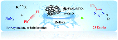
A magnetic nano-Fe3O4@TiO2/Cu2O core–shell composite, optimized for the loading amount of Cu2O, was successfully prepared and fully characterized by analyzing FT-IR, XRD, XPS, FEG-SEM, EDS, and VSM data. The catalytic activity of the nano-Fe3O4@TiO2/Cu2O core–shell composite was examined in a classical one-pot and three-component reaction of terminal alkynes, benzyl halides, and sodium azide in water that was observed to proceed smoothly and completed in good yields with high regioselectivity. The catalyst was conventionally recovered using an external magnet and was reused in at least five successive runs without an appreciable loss of activity.

Introduction

One of the most important developments in catalyzed organic reactions is the synthesis of novel catalysts or reagents that are readily available, inexpensive, selective, recyclable, and environmentally benign.1 In this context, nanoparticles find vast applications due to their high surface-to-volume ratio and their unique electronic properties, resulting in high catalytic activity and tenability.2 Nanocatalysts can often be isolated and recovered through filtration or centrifugation methods. Despite several advantages and merits accompanying the utilization of nanocatalysts, the inconvenience and tedious separation due to the nanosize particles impose few limitations to the sustainability of the nano catalytic strategy in organic synthesis.3

To circumvent the problem of tedious separation, we contemplated using a heterogeneous nanocatalyst that can be operationally separated with a method other than filtration. Magnetite nanoparticles (Fe3O4) have increasingly attracted interest over the past few years due to their unique features, including low preparation cost, high thermal and mechanical stability, and adaptability for large-scale production. Furthermore, their paramagnetic nature allows their simple and efficient separation from the reaction mixture without using standard filtration, which is required for the separation of heterogeneous catalysts. Magnetite nanoparticles (Fe3O4) can be easily separated from a reaction mixture by simply using an external magnet.4–7 However, using naked magnetic nanoparticles (MNPs) is suboptimal because the particles are inherently subjected to aggregation in the reaction mixture, mainly due to their small interparticle distance, high surface energy, and the existence of van der Waals forces.8 This aggregation affects their unique properties that are associated with catalytic reactions. To solve this problem, MNPs are frequently modified using suitable stabilizing coating materials in order to prevent irreversible aggregation, retain their nanoscale properties, and preserve their finely dispersed active sites. Many materials have been explored for use as an outer shell of iron oxides, such as polymers,9 silica,10 titanium dioxide,11 zeolites,12 and carbon.13 Recently, titanium dioxide has attracted great attention as a support due to its unique surface properties, high chemical and thermal stability, non-toxicity, and high catalytic activity, as well as its great accessibility and moderate cost. The appropriate electronic band structure and excellent surface activity endowed TiO2 with very promising potentials in hydrogen production, photovoltaics, photocatalysts, lithium-ion batteries, fuel cells, gas sensors, detoxification, and supercapacitors.14 Thus, further study on the performance of TiO2-based nanostructures is still in much demand. Furthermore, the inclusion of a Fe3O4 core in TiO2 nanospheres makes them easily recoverable with a magnetic field for further possible effective use. In recent years, multi-component reactions (MCRs) have gained eminence as an efficient method to assemble complex molecules with attractive biological features using simple and readily available starting materials in a one-pot operation.15

Among them, Huisgen 1,3-dipolar cycloaddition, which is the reaction of a terminal alkyne and alkyl halide and sodium azide, providing 1,2,3-triazoles, has attracted much attention from biological and chemical points of view. The 1,2,3-triazole moieties are widespread in pharmaceuticals, agrochemicals, dyes, corrosion inhibitors, photostabilizers, and photographic materials.16 Since its discovery, the regioselectivity of the catalyzed Huisgen reaction has been continuously under substantial and wide investigation and has attracted enormous attention of organic chemists, worldwide.17

There has been ongoing interest to develop homogeneous and heterogeneous metal catalysts such as CuO–CeO2,18 nano-Cu,19 Cu/C,20 copper nanoparticles supported on agarose,21 Cu-MOF,22 copper immobilized onto triazole-functionalized magnetic nanoparticles,23 Cu/SiO2,24 ruthenium complex,25 supported CuBr on graphene oxide/Fe3O4[thin space (1/6-em)]26 and mesoporous graphitic carbon nitride27 for a regioselective, three-component reaction of alkyl halides, sodium azide, and terminal alkynes. However, most of the above methods suffer from drawbacks such as the use of organic solvents and tedious experimental procedures to separate the catalyst as well as the requirement for reducing agents and stabilizing ligands. Therefore, there is still much demand to develop an efficient and well-defined heterogeneous catalyst for a one-pot, three-component reaction of terminal alkynes, alkyl halides, and sodium azide.

Recently, we used nano-Fe3O4 as an efficient and easily separable catalyst in different organic reactions.28 As part of our continued interest in multi-component reactions29 and our efforts to develop the regioselective synthesis of 1,4-disubstituted 1,2,3-triazoles via click reaction,30 herein, we wish to report the preparation of a novel and recyclable catalyst system composed of a magnetic Fe3O4 core and TiO2 shell with microcrystals of Cu2O. The Fe3O4@TiO2/Cu2O composite was conveniently prepared, and its structure was fully characterized by XRD, FTIR, XPS, SEM, TEM, EDX, and VSM analysis. The catalytic activity of this system was examined via the model reaction of phenyl acetylene, benzyl bromide, and sodium azide in water, which proceeded smoothly to regioselectively afford the corresponding 1,4-substituted 1,2,3-triazole as the sole product.

Experimental

Materials and instruments

Chemical reagents in high purity were purchased from Merck and Aldrich and were used without further purification. Melting points were determined in open capillaries using an Electrothermal 9100 melting point apparatus without further corrections. 1H NMR and 13C NMR spectra were recorded using a Bruker DRX-400 spectrometer at 400 and 100 MHz, respectively. FT-IR spectra were obtained with potassium bromide pellets in the range of 400–4000 cm−1 using a Shimadzu 8400 s spectrometer. The purity of the synthesized compounds was monitored by TLC on commercial aluminum-backed plates of silica gel 60 F254 and visualized using ultraviolet light. X-ray diffraction (XRD) was detected by Philips using Cu-Kα radiation of wavelength 1.54 Å. Field emission scanning electron microscopy and energy dispersive X-ray (FE-SEM-EDX) analysis was performed using a Tescanvega II XMU digital scanning microscope. Samples were coated with gold at 10 mA for 2 min prior to analysis. The magnetic properties were characterized using a vibrating sample magnetometer (VSM, Lakeshore7407) at room temperature. XPS spectra of the sample were obtained using a Gammadata-scienta ESCA 200 hemispherical analyzer equipped with an Al Kα (1486.6 eV) X-ray source.

Preparation of composite

Preparation of Fe3O4. The nano-Fe3O4 particles were prepared in accordance with a protocol that was described in our earlier report.28
Preparation of nano-Fe3O4@TiO2. Nano-Fe3O4@TiO2 was synthesized according to a previously reported method,31 subjected to modification. The prepared nanomagnetic Fe3O4 particles were dispersed in a mixture of 250 mL of absolute ethanol/90 mL of acetonitrile. This mixture was sonicated for 15 min, and then 1.5 mL of NH3·H2O solution (25 wt%) was added. After continuous mechanical stirring for 30 min, 3 mL of tetrabutyl titanate (TBOT) dissolved in 20 mL of absolute ethanol was added dropwise to the above suspension under continuous mechanical stirring at 30 °C. The reaction mixture was further mechanically stirred for 1.5 h to obtain Fe3O4@TiO2 core–shell nanoparticles. The obtained product was collected by magnetic separation and washed three times with absolute ethanol.
Preparation of nano-Fe3O4@TiO2/Cu2O core–shell magnetic composite. Four types of composites with different molar ratios of Fe3O4@TiO2[thin space (1/6-em)]:[thin space (1/6-em)]Cu2O were synthesized. Nano-Fe3O4@TiO2 (0.036–0.324 g) was dispersed in 80 mL of deionized water. 5 mL of (0.1 mol L−1) CuCl2 solution was added to the aqueous Fe3O4@TiO2, and then the solution was sonicated for 15 min. Next, 1.8 mL of (1.0 mol L−1) NaOH solution was added dropwise under ultrasonic radiation. The resulting solution instantly turned light blue, indicating the formation of Cu(OH)2. Then, 12 mL of (0.1 mol L−1) NH2OH·HCl was immediately injected over 5 s into the solution. The solution was kept in a water bath for 1 h and centrifuged for 3 min, and then the solution was decanted as much as possible. The remaining precipitate was washed three times with 6 mL of a 1[thin space (1/6-em)]:[thin space (1/6-em)]1 volume ratio of water and ethanol. The nano-Fe3O4@TiO2/Cu2O was collected as a brown solid that can be stored in a tightly sealed vessel for several months without any changes in color or activity.

General procedure for synthesis of 1,2,3-triazoles

In a round-bottomed flask, an appropriate alpha-haloketone (1 mmol) or alkyl halide (1 mmol), terminal alkyne (1 mmol), and sodium azide (1.1 mmol) were placed in water (10 mL). To this mixture, a nano-Fe3O4@TiO2/Cu2O magnetic composite (0.01 g) was added. The suspension was magnetically stirred under reflux for the indicated time (Table 3). The progress of the reaction was monitored by TLC (n-hexane[thin space (1/6-em)]:[thin space (1/6-em)]ethyl acetate; 7[thin space (1/6-em)]:[thin space (1/6-em)]3). After the completion of the reaction, the solution was decanted as much as possible. The leftover residue was diluted with hot ethanol, and then the catalyst was separated from this mixture by an external magnet and washed with acetone (2 × 10 mL), dried in an oven, and stored for use in subsequent runs under the same conditions. After separation of the catalyst, the solution was evaporated to dryness, and a crude product was obtained. The crude products in some cases were washed with 10 mL of ether and were re-crystallized from EtOH[thin space (1/6-em)]:[thin space (1/6-em)]H2O (3[thin space (1/6-em)]:[thin space (1/6-em)]1 v/v) to afford pure crystalline products. Some products had to be purified by chromatography on silica gel using a short column (Table 3).

Results and discussion

Synthesis of composite

Scheme 1 shows an illustration for the synthesis of the Fe3O4@TiO2/Cu2O core–shell magnetic composite. The Fe3O4@TiO2 based on Cu2O composite was prepared from inexpensive commercially available materials. In the first step, the magnetic Fe3O4 nanoparticles were prepared by the co-precipitation of Fe(II) and Fe(III) ions in alkali medium. The TiO2 shell was prepared by the hydrolysis of tetrabutyl titanate (TBOT) in an absolute ethanol–acetonitrile mixture in the presence of well-dispersed Fe3O4 nanocrystals by a sol–gel process. The as-prepared Fe3O4@TiO2 nanoparticles were removed by magnetic separation. The Fe3O4@TiO2/Cu2O composite was obtained by reducing Cu(II) hydroxide using hydroxylamine hydrochloride in the presence of Fe3O4@TiO2.
image file: c5ra06810j-s1.tif
Scheme 1 Preparation of nano-Fe3O4@TiO2/Cu2O core–shell composite.

The structure of Fe3O4@TiO2/Cu2O composite was fully characterized using the corresponding data provided by FT-IR, SEM, TEM, XRD, XPS, and VSM techniques.

Structural characterization of the composite

FT-IR spectra

Fig. 1 gives the FT-IR spectral pattern of Fe3O4, Fe3O4@TiO2, and Fe3O4@TiO2/Cu2O in the range of 4000–500 cm−1. The FT-IR spectra show a broad peak at 700–500 cm−1, which is attributed to the vibration of the Metal-O functional group. The peak appearing at approximately 545 cm−1 can be assigned to the vibration of the Fe–O functional group.32 Ti–O and Cu–O absorption peaks appeared at approximately 500 and 625 cm−1, respectively. Notably, in the Fe3O4@TiO2 and Fe3O4@TiO2/Cu2O samples, the observed peak is relatively broader. This may be attributed to the overlapping of Fe–O, Ti–O, and Cu–O peaks. The peaks appearing at 1118 and 1465 cm−1 for the Fe3O4@TiO2 and Fe3O4@TiO2/Cu2O samples could be associated with the presence of stretching vibrations of Ti–O and Fe–O–Ti bonds.33 The bands at 1628 cm−1 belong to the H–O–H bending vibration, indicating that several OH groups are present in the sample as a result of TiO2 coating.
image file: c5ra06810j-f1.tif
Fig. 1 The FT-IR spectra of Fe3O4, Fe3O4@TiO2, and Fe3O4@TiO2/Cu2O.

X-ray diffraction spectra

Fig. 2 shows the X-ray diffraction patterns of Fe3O4@TiO2 and as-made samples with different Cu2O molar ratios (from 9[thin space (1/6-em)]:[thin space (1/6-em)]1 to 6[thin space (1/6-em)]:[thin space (1/6-em)]4 molar ratio of Fe3O4@TiO2 to Cu2O). The typical diffraction peaks located approximately at 30.1, 35.5, 43.2, 53.4, 57.1, and 62.7 can be well assigned to the diffraction of Fe3O4 nanoparticles with cubic phase from the (220), (311), (400), (422), (511), and (440) planes, respectively. In addition, a broad diffraction peak appearing at 2θ = 20–30 nm can be indexed to amorphous TiO2.34 The main peaks for Fe3O4@TiO2 are similar to the standard Fe3O4 particles (JCPDS card no. 19-629), which reveal that the crystal structure of Fe3O4@TiO2 is well coated. No obvious diffraction peak for TiO2 is observed, suggesting that an amorphous TiO2 coating is formed by the hydrolysis of tetrabutyl titanate (TBOT) in the presence of the well-dispersed Fe3O4 nanocrystals by a sol–gel process. Compared to Fe3O4@TiO2, new diffraction peaks located at 29.5 (110), 36.7 (111), 42.5 (200), 52.7 (211), 61.6 (220), and 73.7 (311) can be indexed to the diffraction of Cu2O rhombic dodecahedral crystals in the cubic phase (JCPDS card no. 05-0667), which suggests the presence of Cu2O in the desired prepared composites. No additional diffraction peaks were observed, indicating the complete reduction of Cu(II) to Cu(I). It was also observed that by increasing the Cu2O content in the samples, the intensity of the XRD patterns gradually becomes stronger due to the increase in the Cu2O/Fe3O4@TiO2 weight ratio.
image file: c5ra06810j-f2.tif
Fig. 2 XRD patterns of Fe3O4@TiO2 and Fe3O4@TiO2/Cu2O with different weight ratios.

FE-SEM-EDS and TEM analysis

The morphology and chemical purity of Fe3O4, Fe3O4@TiO2, and Fe3O4@TiO2/Cu2O core–shell composites (optimized amounts) were visualized by SEM and EDX analysis (Fig. 3). The appearance of elemental Au in the EDX analysis as well as the SEM characterization proves that the material was coated by a layer of Au. The SEM image of Fe3O4 shows that nearly spherical nanoparticles were obtained with an average diameter of 15–20 nm. Moreover, the energy-dispersive X-ray (EDAX) spectrum depicted in Fig. 4b indicated that the product is mainly composed of nano-Fe3O4. It can be observed from Fig. 3c that the as-synthesized Fe3O4@TiO2 core–shell is still maintaining the morphological properties of Fe3O4 except for a slightly larger particle size and stifled surface, where TiO2 is uniformly coated on the Fe3O4 particles. The EDAX spectrum shows that the Fe3O4@TiO2 (Fig. 3d) core–shell nanoparticles are elementally composed of Fe, Ti, and O.
image file: c5ra06810j-f3.tif
Fig. 3 The FEG-SEM-EDS analysis of (a and b) Fe3O4, (c and d) Fe3O4@TiO2, and (e and f) Fe3O4@TiO2/Cu2O (8[thin space (1/6-em)]:[thin space (1/6-em)]2) composite.

image file: c5ra06810j-f4.tif
Fig. 4 TEM image of the Fe3O4@TiO2/Cu2O (8[thin space (1/6-em)]:[thin space (1/6-em)]2) composite.

Fig. 3e shows the SEM image of the Fe3O4@TiO2/Cu2O composite with the optimized amount of Cu2O required for catalytic activity in the synthesis of 1,4-disubstituted 1,2,3-triazoles. The Cu2O shows a rhombic dodecahedral structure and can be easily distinguished from the hybrid material by its different shape, as marked in Fig. 3e. The EDX analysis of the obtained Fe3O4@TiO2/Cu2O composite reveals the existence of elemental Fe, Ti, Cu, and O, re-confirming the formation of Cu2O species on the Fe3O4@TiO2 nanospheres.

The TEM image in Fig. 4 vividly shows a uniform coating of thin-layer TiO2 (approximately 4 nm) around the entire surface of the Fe3O4 (approximately 20 nm). The Cu2O is a bigger and dark particle that can be seen and distinguished in the TEM image.

Magnetization study

The magnetic properties of synthesized Fe3O4, Fe3O4@TiO2, and Fe3O4@TiO2/Cu2O core–shell composite were assessed by a vibrating sample magnetometer at ambient temperature. As illustrated in Fig. 5, the saturation magnetization of the Fe3O4 MNPs is 61.6 emu g−1, and those for Fe3O4@TiO2 and the Fe3O4@TiO2/Cu2O core–shell composite are 29.9 and 24.11 emu g−1, respectively. The decrease in the saturation magnetization of Fe3O4 MNPs after surface coating with TiO2 and Cu2O can be ascribed to the contribution of the non-magnetic materials. Nonetheless, there was adequate magnetism so that the Fe3O4@TiO2/Cu2O core–shell composite could be completely, efficiently, and rapidly separated from the reaction mixture.
image file: c5ra06810j-f5.tif
Fig. 5 The magnetization curves of Fe3O4, Fe3O4@TiO2, and Fe3O4@TiO2/Cu2O.

XPS analysis

The XPS elemental survey scans of the surface of the Fe3O4@TiO2/Cu2O composite are shown in Fig. 6. The peaks, corresponding to oxygen, titanium, and copper, are clearly observed.
image file: c5ra06810j-f6.tif
Fig. 6 XPS pattern of the as-synthesized Fe3O4@TiO2/Cu2O composite.

The corresponding high resolution XPS spectra of the Ti2p, O1s, and Cu2p regions are shown in Fig. 7. The Ti2p XPS spectra showed two major peaks with binding energies of approximately 466.5 and 472.1, corresponding to Ti2p3/2 and Ti2p1/2, respectively, and characteristic of the presence of the TiO2 phase (Fig. 7a).35 Fe signals were not observed, indicating that the Fe3O4 core was well coated by the TiO2 shell. The observed carbon peak belongs to the carbon tape that is used for XPS analysis. The peak at 931.8 eV is assigned to Cu2p3/2, and the other peak at 952.54 eV is assigned to Cu2p1/2. The additional peaks assigned to Cu2p3/2 and Cu2p1/2 are the two shake-up satellite peaks, appearing at binding energies of 942.3 and 962.5 eV. These are expected for an open 3d6 shell and correspond to the Cu1+ state; they are assigned to Cu2O in accordance with the data given in literature.36 The O1s peak at 538.3 eV found over the catalyst surface can be assigned to OH species in the composite.


image file: c5ra06810j-f7.tif
Fig. 7 High resolution XPS spectra of the Fe3O4@TiO2/Cu2O composite showing (a) Ti2p, (b) Cu2p, and (c) O1s.

Catalytic application of the Fe3O4@TiO2/Cu2O core–shell magnetic composite

After the successful preparation and full characterization of the Fe3O4@TiO2/Cu2O core–shell magnetic composite, its catalytic activity in different weight ratios of Cu2O were examined by a model reaction of benzyl bromide, phenyl acetylene, and sodium azide (Huisgen cycloaddition reaction), to obtain 1-benzyl-4-phenyl-1H-1,2,3-triazole 4a (Scheme 2) as the sole product using a 0.01 g magnetic composite under reflux in water. The products were obtained in high yield and with excellent regioselectivity. The result showed that this click reaction proceeded regioselectively, among the other merits concluded from the use of this novel catalyst system for the aforementioned model reaction. In order to establish the strategy, various terminal alkynes, different substituted benzyl bromides, and sodium azide were reacted in the presence of catalytic amounts of Fe3O4@TiO2/Cu2O core–shell to afford the corresponding 1,4-disubstituted-1,2,3-triazoles, regioselectively and in good yields (Table 3).
image file: c5ra06810j-s2.tif
Scheme 2 Click reaction catalysed by the nano-Fe3O4@TiO2/Cu2O core–shell composite.

As shown in Table 1, the catalytic performance of the Fe3O4@TiO2/Cu2O magnetic composite with a weight ratio of 8[thin space (1/6-em)]:[thin space (1/6-em)]2 gave the best result. It was found that no change in yield was obtained with an increase of Cu2O loading in the magnetic composite. Therefore, the weight ratio of 8[thin space (1/6-em)]:[thin space (1/6-em)]2 for Fe3O4@TiO2[thin space (1/6-em)]:[thin space (1/6-em)]Cu2O was selected as one of the optimal reaction conditions. The reaction of benzyl bromide (1 mmol), phenylacetylene (1 mmol), and sodium azide (1.3 mmol) was also conducted in various solvents, at different temperatures, and with various loading amounts of the magnetic composite.

Table 1 Optimization of Cu2O for the magnetic composite in the model reactiona
Entry Fe3O4@TiO2 (%) Cu2O (%) Yieldb (%)
a Reaction conditions: benzyl bromide (1 mmol), sodium azide (1.3 mmol), phenylacetylene (1 mmol), and catalyst (0.010 g) in water under reflux.b Isolated yield.
1 60 40 93
2 70 30 93
3 80 20 93
4 90 10 82


The results for the optimization of the reaction conditions are summarized in Table 2. The reaction performed in refluxing water gave the highest product yield, indicating that an inert atmosphere is not required (Table 2, entry 7). We carried out the model reaction in the presence of Fe3O4@TiO2 as a catalyst under reflux in water, and even after 2 h, the product yield was poor (Table 2, entry 8). As expected, the reaction did not proceed in the absence of the catalyst, even after a prolonged reaction time (Table 2, entry 9). This indicates that the magnetic composite as catalyst plays a crucial role in the regioselective synthesis of 1-benzyl-4-phenyl-1H-1,2,3-triazole 4a. A higher reaction temperature or catalyst amount did not make an obvious difference in the product yield (Table 2, entries 6 and 10). However, a lower amount of catalyst decreased the yield of the reaction.

Table 2 Optimization of the three-component click synthesis of 4-phenyl-1H-1,2,3-triazole 4a, using a Fe3O4@TiO2/Cu2O magnetic compositea
Entry Catalyst (g) Condition Time (h:min) Yieldb (%)
a Reaction condition: benzyl bromide (1 mmol), sodium azide (1.3 mmol), and phenylacetylene (1 mmol).b Isolated yield.
1 Fe3O4@TiO2/Cu2O (0.020) H2O/r.t 2 Trace
2 Fe3O4@TiO2/Cu2O (0.020) H2O/60 °C 0:15 43
3 Fe3O4@TiO2/Cu2O (0.020) H2O/80 °C 0:15 79
4 Fe3O4@TiO2/Cu2O (0.020) H2O/110 °C 0:15 91
5 Fe3O4@TiO2/Cu2O (0.010) H2O/reflux 0:15 69
6 Fe3O4@TiO2/Cu2O (0.015) H2O/reflux 0:15 82
7 Fe3O4@TiO2/Cu2O (0.020) H2O/reflux 0:15 93
8 Fe3O4@TiO2 (0.020) H2O/reflux 2 Trace
9 H2O/reflux 24
10 Fe3O4@TiO2/Cu2O (0.025) H2O/reflux 0:15 93
11 Fe3O4@TiO2/Cu2O (0.020) H2O/DMSO (2[thin space (1/6-em)]:[thin space (1/6-em)]1)/reflux 1:40 58
12 Fe3O4@TiO2/Cu2O (0.020) CH3CN/reflux 1 75
13 Fe3O4@TiO2/Cu2O (0.020) EtOH/reflux 0:45 86
14 Fe3O4@TiO2/Cu2O (0.020) DMF/100 °C 1:45 46
15 Fe3O4@TiO2/Cu2O (0.020) DMSO/100 °C 1:45 50
16 Fe3O4@TiO2/Cu2O (0.020) Solvent free/100 °C 2 65


Thus, with the optimized reaction conditions in hand, the substrate scope of reaction was extended to various structurally diverse terminal alkynes and benzyl halides (Table 3). In an attempt to broaden the generality of the Fe3O4@TiO2/Cu2O magnetic composite, we further investigated the possibility of reaction of phenacyl bromide with various terminal alkynes and sodium azide in the presence of our novel catalyst and found it promising and fruitful (Scheme 3). The results are listed in Table 4. Under optimal conditions for this one-pot, multi-component reaction, phenacyl bromide 1 mmol, phenylacetylene 1 mmol, and sodium azide 1.3 mmol were reacted in the presence of 0.01 g magnetic composite under reflux in water.

Table 3 Three-component click reaction of benzyl halides, terminal alkynes, and sodium azide using a Fe3O4@TiO2/Cu2O magnetic compositea
Entry Halide precursor Alkyne Product Time (min) Yieldb (%) Mp. °C Lit
a Reaction condition: alkyl halide (1 mmol), NaN3 (1.3 mmol), acetylene (1 mmol), Fe3O4@TiO2/Cu2O (0.020 g), H2O (2 mL), reflux.b Isolated yield.
1 image file: c5ra06810j-u1.tif image file: c5ra06810j-u2.tif image file: c5ra06810j-u3.tif 15 93 127–128 (126–127)30d
2 image file: c5ra06810j-u4.tif image file: c5ra06810j-u5.tif image file: c5ra06810j-u6.tif 20 89 104–106 (105–106)39
3 image file: c5ra06810j-u7.tif image file: c5ra06810j-u8.tif image file: c5ra06810j-u9.tif 30 84 153–156 (156–157)39
4 image file: c5ra06810j-u10.tif image file: c5ra06810j-u11.tif image file: c5ra06810j-u12.tif 20 87 147–149 (150)40
5 image file: c5ra06810j-u13.tif image file: c5ra06810j-u14.tif image file: c5ra06810j-u15.tif 20 91 77–79 (78–78.5)39
6 image file: c5ra06810j-u16.tif image file: c5ra06810j-u17.tif image file: c5ra06810j-u18.tif 20 85 76–77 (77)39
7 image file: c5ra06810j-u19.tif image file: c5ra06810j-u20.tif image file: c5ra06810j-u21.tif 20 89 127–128 (126–127)30d
8 image file: c5ra06810j-u22.tif image file: c5ra06810j-u23.tif image file: c5ra06810j-u24.tif 25 83 104–106 (105–106)38
9 image file: c5ra06810j-u25.tif image file: c5ra06810j-u26.tif image file: c5ra06810j-u27.tif 25 84 143–146 (142–145)41
10 image file: c5ra06810j-u28.tif image file: c5ra06810j-u29.tif image file: c5ra06810j-u30.tif 25 84 147–149 (150)40
11 image file: c5ra06810j-u31.tif image file: c5ra06810j-u32.tif image file: c5ra06810j-u33.tif 20 89 77–79 (78–78.5)39
12 image file: c5ra06810j-u34.tif image file: c5ra06810j-u35.tif image file: c5ra06810j-u36.tif 25 86 76–77 (77)39


image file: c5ra06810j-s3.tif
Scheme 3 Click reaction of phenacyl bromide, phenylacetylene, and sodium azide.
Table 4 Three-component click reaction of phenacyl halides, terminal alkynes, and sodium azide using a Fe3O4@TiO2/Cu2O magnetic compositea
Entry Phenacyl halide Alkyne Product Time (min) Yieldb (%) Mp. °C Lit
a Reaction condition: α-haloketones (1 mmol), NaN3 (1.3 mmol), acetylene (1 mmol), Fe3O4@TiO2/Cu2O (0.020 g), H2O (2 mL), reflux.b Isolated yield.
1 image file: c5ra06810j-u37.tif image file: c5ra06810j-u38.tif image file: c5ra06810j-u39.tif 20 89 169–171 (171–172)30d
2 image file: c5ra06810j-u40.tif image file: c5ra06810j-u41.tif image file: c5ra06810j-u42.tif 25 83 115–118 (116–119)30d
3 image file: c5ra06810j-u43.tif image file: c5ra06810j-u44.tif image file: c5ra06810j-u45.tif 25 86 102–104 (100–103)30d
4 image file: c5ra06810j-u46.tif image file: c5ra06810j-u47.tif image file: c5ra06810j-u48.tif 30 87 157–159 (156–158)30d
5 image file: c5ra06810j-u49.tif image file: c5ra06810j-u50.tif image file: c5ra06810j-u51.tif 50 76 111–113 (110–113)30d
6 image file: c5ra06810j-u52.tif image file: c5ra06810j-u53.tif image file: c5ra06810j-u54.tif 60 75 180–183 (180–183)30d
7 image file: c5ra06810j-u55.tif image file: c5ra06810j-u56.tif image file: c5ra06810j-u57.tif 50 82 156–158 (157–160)30a
8 image file: c5ra06810j-u58.tif image file: c5ra06810j-u59.tif image file: c5ra06810j-u60.tif 75 80 153–155 (151–154)30a
9 image file: c5ra06810j-u61.tif image file: c5ra06810j-u62.tif image file: c5ra06810j-u63.tif 70 78 154–155 (154–155)30d
10 image file: c5ra06810j-u64.tif image file: c5ra06810j-u65.tif image file: c5ra06810j-u66.tif 80 76 168–171 (167–170)30d


In general, different substituted phenylacetylenes and benzyl halides bearing electron-donating substituents as well as electron-withdrawing groups smoothly and cleanly provided an array of 1,4-disubstituted 1,2,3-triazoles, in good to excellent yields (75–93%) within relatively short reaction times of 15–80 min. As shown in Tables 3 and 4, the aliphatic terminal alkynes bearing hydroxyl as a functional group gave the desired triazoles in higher yields.

Recycling and leaching of the catalyst

One of the main advantages of heterogeneous catalysis is the ease of separation and possible reusability in further runs.37 Thus, the recyclability of the Fe3O4@TiO2/Cu2O magnetic composite was examined in a one-pot synthesis of 1-benzyl-4-phenyl-1H-1,2,3-triazole 4a under optimized conditions. No significant loss in catalytic activity was observed after five runs, suggesting that Cu2O leaching is not meaningful for the Fe3O4@TiO2/Cu2O magnetic composite (Fig. 8). Another test was performed to determine if the dissolved CuI species in the solution was solely responsible for the catalytic activity of the Fe3O4@TiO2/Cu2O composite. An unfinished experiment was performed whereby we took starting materials and catalyst, the Fe3O4@TiO2/Cu2O composite, in 3 mL water and refluxed the mixture for 5 min to simulate the actual conditions. At this point, the catalyst was removed by an external magnet while we allowed the reaction to normally proceed. Then we permitted the mixture to reflux in the absence of the magnetically removed catalyst. No appreciable progress was observed even after 2 h (monitored by TLC). Thus, it can be concluded that the dissolved CuI species is not actually involved in catalysis, at least solely by itself.
image file: c5ra06810j-f8.tif
Fig. 8 The recycling results of the Fe3O4@TiO2/Cu2O composite.

Conclusion

In summary, we have developed an efficient method for the regioselective synthesis of 1,4-disubstituted 1,2,3-triazoles through a one-pot multi-component reaction of alkyl halides or phenacyl bromide, terminal alkynes, and sodium azide, catalyzed by a novel and well-characterized nano-Fe3O4@TiO2/Cu2O core–shell magnetic composite under reflux in water. The merits of this method are that commercially and readily available starting materials are used, and water is used as the solvent, which is green and abundant. Conducting the reaction under conventional conditions with a convenient workup procedure, easy recovery, and efficient reusability of catalyst are conspicuous features of this methodology. Further studies on the scope and application of nano-Fe3O4@TiO2/Cu2O magnetic composite are underway in our laboratory.

Acknowledgements

The authors gratefully acknowledge Semnan University Research Council for financial support of this work.

References

  1. P. Hu, J. V. Morabito and C. K. Tsung, ACS Catal., 2014, 4, 4409–4419 CrossRef CAS.
  2. F. Shirini and F. Absdini, J. Nanosci. Nanotechnol., 2013, 13, 4838–4860 CrossRef CAS PubMed.
  3. T. Cheng, D. Zhang, H. Li and G. Liu, Green Chem., 2014, 16, 3401–3427 RSC.
  4. R. Mŕowczýnski, A. Nanb and J. Liebscher, RSC Adv., 2014, 4, 5927–5952 RSC.
  5. A. Kumar, R. Parella and S. A. Babu, Synlett, 2014, 25, 835–842 CrossRef CAS PubMed.
  6. S. Shylesh, V. Schünemann and W. R. Thiel, Angew. Chem., Int. Ed., 2010, 49, 3428–3459 CrossRef CAS PubMed.
  7. M. B. Gawande, P. S. Branco and R. S. Varma, Chem. Soc. Rev., 2013, 42, 3371–3393 RSC.
  8. R. Hudson, Y. Feng, R. S. Varma and A. Moores, Green Chem., 2014, 16, 4493–4505 RSC.
  9. X. Zhu, J. Niu, F. Zhang, J. Zhou, X. Li and J. Ma, New J. Chem., 2014, 38, 4622–4627 RSC.
  10. S. P. Pujari, L. Scheres, A. T. M. Marcelis and H. Zuilhof, Angew. Chem., Int. Ed., 2014, 53, 6322–6356 CrossRef CAS PubMed.
  11. S. Xuan, W. Jiang, X. Gong, Y. Hu and Z. Chen, J. Phys. Chem. C, 2009, 113, 553–558 CAS.
  12. T. A. Salah El-Din, A. A. Elzatahry, D. M. Aldhayan, A. M. Al-Enizi and S. S. Al-Deyab, Int. J. Electrochem. Sci., 2011, 6, 6177–6183 CAS.
  13. Z. Chen, Z. Xue, L. Chen, Z. Geng, R. Yang, L. Chena and Z. Wang, New J. Chem., 2013, 37, 3731–3736 RSC.
  14. (a) X. Wang, Z. Li, J. Shi and Y. Yu, Chem. Rev., 2014, 114, 9346–9384 CrossRef CAS PubMed; (b) M. Pelaez, N. T. Nolan, S. C. Pillai, M. K. Seery, P. Falaras, A. G. Kontos, P. S. M. Dunlop, J. W. J. Hamiltone, J. Anthony Byrne, K. O'Shea, M. H. Entezari and D. D. Dionysiou, Appl. Catal., B, 2012, 125, 331–349 CrossRef CAS PubMed.
  15. (a) C. Allais, J.-M. Grassot, J. Rodriguez and T. Constantieux, Chem. Rev., 2014, 114, 10829–10868 CrossRef CAS PubMed; (b) H. G. O. Alvim, E. N. J. da S. Jumior and B. N. D. Neto, RSC Adv., 2014, 4, 54282–54299 RSC; (c) H. Y. Cho and J. P. Morken, Chem. Soc. Rev., 2014, 43, 4368–4380 RSC; (d) V. Estevez, M. Villacampa and J. C. Menendez, Chem. Soc. Rev., 2014, 43, 4633–4657 RSC.
  16. (a) M. K. Singh, R. Tilak, G. Nath, R. S. K. Awasthi and A. Agarwal, Eur. J. Med. Chem., 2013, 63, 635–644 CrossRef CAS PubMed; (b) M. Whiting, J. Muldoon, Y. C. Lin, S. M. Silverman, W. Lindstrom, A. J. Olson, H. C. Kolb, M. J. Fine, K. B. Sharpless, J. H. Elder and V. V. Fokin, Angew. Chem., Int. Ed., 2006, 45, 1435–1439 CrossRef CAS PubMed; (c) Z. Ke, H. F. Chow, M. C. Chan, Z. Liu and K. H. Sze, Org. Lett., 2012, 14, 394–397 CrossRef CAS PubMed; (d) Y. Hua and A. H. Flood, Chem. Soc. Rev., 2010, 1262–1271 RSC.
  17. (a) A. Lauria, R. Delisi, F. Mingoia, A. Terenzi, A. Martorana, G. Barone and A. M. Almerico, Eur. J. Org. Chem., 2014, 79, 3289–3306 CrossRef PubMed; (b) X. Xiong and L. Cai, Catal. Sci. Technol., 2013, 3, 1301–1307 RSC; (c) B. Kaboudin, R. Mostafalu and T. Yokomatsu, Green Chem., 2013, 15, 2266–2274 RSC; (d) N. Aslam, N. A. Babu, S. Arulanda, D. Kuma and R. Ameet, Synlett, 2014, 25, 2201–2207 CrossRef PubMed.
  18. J. Albadi, J. Abbasi Shiran and A. Mansurnezhad, J. Chem. Sci., 2014, 126, 147–150 CrossRef CAS.
  19. L. Huang, W. Liu, J. Wu, Y. Fu, K. Wang, C. Huo and Z. Du, Tetrahedron Lett., 2014, 55, 2312–2316 CrossRef CAS PubMed.
  20. F. Alonso, Y. Moglie, G. Radivoy and M. Yusv, Adv. Synth. Catal., 2010, 352, 3208–3214 CrossRef CAS PubMed.
  21. M. Gholinejad and N. Jeddi, ACS Sustainable Chem. Eng., 2014, 2, 2658–2665 CrossRef CAS.
  22. P. Li, S. Regati, H. Huang, H. D. Arman, J. C. G. Zhao and B. Chen, Inorg. Chem. Front., 2015, 2, 42–46 RSC.
  23. F. Matloubi Moghaddam and S. E. Ayati, RSC Adv., 2015, 5, 3894–3902 RSC.
  24. C. Schwartz Radatz, L. Amaral Soares, E. Roberto Vieira, D. Alves, D. Russowsky and P. Henrique Schneider, New J. Chem., 2014, 38, 1410–1417 RSC.
  25. H. X. Siyang, H. L. Liu, X. Y. Wu and P. N. Liu, RSC Adv., 2015, 5, 4693–4697 RSC.
  26. X. Xiong, H. Chen, Z. Tang and Y. Jiang, RSC Adv., 2014, 4, 9830–9837 RSC.
  27. S. Dadashi-Silab, B. Kiskan, M. Antonietti and Y. Yagci, RSC Adv., 2014, 4, 52170–52173 RSC.
  28. (a) F. Nemati, M. M. Heravi and R. Saeedi rad, Chin. J. Catal., 2012, 33, 1825–1831 CrossRef CAS; (b) F. Janati, M. M. Heravi and A. M. Shokraie, Synth. React. Inorg., Met.-Org., Nano-Met. Chem., 2015, 45, 1–5 CrossRef CAS PubMed; (c) T. Alishiri, H. A. Oskooei and M. M. Heravi, Synth. Commun., 2013, 43, 3357–3362 CrossRef CAS PubMed.
  29. (a) M. M. Heravi and Z. Faghihi, J. Iran. Chem. Soc., 2014, 11, 209–224 CrossRef CAS; (b) M. M. Heravi and S. Moghimi, Tetrahedron Lett., 2012, 53, 392–394 CrossRef CAS PubMed; (c) M. M. Heravi and S. Moghimi, J. Iran. Chem. Soc., 2011, 8, 306–373 CrossRef CAS; (d) M. M. Heravi, F. K. Behbahani, M. Daraie and H. A. Oskooie, Mol. Diversity, 2009, 13, 375–378 CrossRef CAS PubMed; (e) M. M. Heravi, E. Hashemi, Y. S. Beheshtiha, K. Kamjou, M. Toolabi and N. Hosseintash, J. Mol. Catal. A: Chem., 2014, 392, 173–180 CrossRef CAS PubMed; (f) M. M. Heravi, F. Mousavizadeh, N. Ghobadi and M. Tajbakhsh, Tetrahedron Lett., 2014, 55, 1226–1228 CrossRef CAS PubMed; (g) M. M. Heravi, S. Asadi and B. M. Lashkariani, Mol. Diversity, 2013, 17, 389–407 CrossRef CAS PubMed.
  30. (a) A. Fazeli, H. A. Oskooie, Y. S. Beheshtiha, M. M. Heravil and H. Valizadeh, Lett. Org. Chem., 2013, 10, 738–743 CrossRef CAS; (b) A. Fazeli, H. A. Oskooie, Y. S. Beheshtiha, M. M. Heravi, H. Valizadeh and F. F. Bamoharram, Monatsh. Chem., 2013, 144, 1407–1410 CrossRef PubMed; (c) M. M. Heravi, A. Fazeli, H. A. Oskooie, Y. S. Beheshtiha and H. Valizadeh, Synlett, 2012, 23, 2927–2930 CrossRef CAS PubMed; (d) E. Hashemi, Y. S. Beheshtiha, S. Ahmadi and M. M. Heravi, Transition Met. Chem., 2014, 39, 593–601 CrossRef CAS PubMed; (e) M. M. Heravi, H. Hamidi and V. Zadsirjan, Curr. Org. Synth., 2014, 11, 647–675 CrossRef CAS; (f) R. Mirsafaei, M. M. Heravi, S. Ahmadi, M. S. Moslemin and T. Hosseinnejad, J. Mol. Catal. A: Chem., 2015, 402, 100–108 CrossRef CAS PubMed.
  31. W. Hu, B. Liu, Q. Wang, Y. Liu, Y. Liu, P. Jing, S. Yu, L. Liua and J. Zhang, Chem. Commun., 2013, 49, 7596–7598 RSC.
  32. R. J. Watts, S. Kong and W. Lee, J. Environ. Eng., 1995, 121, 730–735 CrossRef CAS.
  33. T. Xin, M. Ma, H. Zhang, J. Gu, S. Wang, M. Liu and Q. Zhang, Appl. Surf. Sci., 2014, 288, 51–59 CrossRef CAS PubMed.
  34. H. Yin, Y. Wada, T. Kitamura, S. Kambe, S. Murasawa, H. Mori, T. Sakatac and S. Yanagida, J. Mater. Chem., 2001, 11, 1694–1703 RSC.
  35. F. Niu, Y. Jiang and W. Song, Nano Res., 2010, 3, 757–763 CrossRef CAS PubMed.
  36. C. H. Kuo, Y. T. Chu, Y. F. Song and M. H. Huang, Adv. Funct. Mater., 2011, 21, 792–797 CrossRef CAS PubMed.
  37. (a) D. Diaz, D. Kuehbeck and R. Koopmans, J. Chem. Soc. Rev., 2011, 40, 427–448 RSC; (b) M. M. Heravi and S. Sadjadi, J. Iran Chem. Soc., 2009, 6, 1–54 CrossRef CAS.
  38. J. Gonź alez, V. M. Pérez, D. O. Jiménez, G. Lopez-Valdez, D. Corona and E. Cuevas-Yãnez, Tetrahedron Lett., 2011, 52, 3514–3517 CrossRef PubMed.
  39. H. Sharghi, R. Khalifeh and M. M. Doroodmand, Adv. Synth. Catal., 2009, 351, 207–218 CrossRef CAS PubMed.
  40. Z. Gonda and Z. Novak, Dalton Trans., 2010, 39, 726–729 RSC.
  41. P. V. Chavan, K. S. Pandit, U. V. Desai, M. A. Kulkarni and P. P. Wadgaonkar, RSC Adv., 2014, 4, 42137–42146 RSC.

This journal is © The Royal Society of Chemistry 2015