Preparation and catalytic applications of nanomaterials: a review

Navneet Sharma a, Himanshu Ojha b, Ambika Bharadwaj a, Dharam Pal Pathak c and Rakesh Kumar Sharma *a
aDivision of CBRN Defence, Institute of Nuclear Medicine and Allied Sciences, Brig. S. K. Mazumdar Road, Delhi 110 054, India. E-mail: rksharmadrl@yahoo.com; Fax: +91-11-23919509; Tel: +91-11-23905190
bDivision of Radiation Biosciences, Institute of Nuclear Medicine and Allied Sciences, Brig. S. K. Mazumdar Road, Delhi 110 054, India
cDelhi Institute of Pharmaceutical Sciences and Research, University of Delhi, Sector 3, Pushp Vihar, New Delhi 10017, India

Received 15th April 2015 , Accepted 1st June 2015

First published on 1st June 2015


Abstract

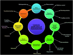
Catalysts play a very important role in the chemical industries. Catalysts have been used in processes like the workup of fuels such as oil, gas and coal, purification of effluents and industrial waste gases etc. Heterogeneous catalysts are gaining much attention compared to homogeneous catalysts as they confer more selectivity and provide better yield. Research in new catalytic materials or optimization of existing catalyst systems is of enormous importance in order to increase the efficiency of the catalyst, resulting in higher product yields and purities. Currently, the research is more focused towards nanostructured catalysts with enhanced physiochemical properties. Nanoscale catalysts have high specific surface area and surface energy, which ultimately lead to the high catalytic activity. Nano-catalysts improve the selectivity of the reactions by allowing reaction at a lower temperature, reducing the occurrence of side reactions, higher recycling rates and recovery of energy consumption. Therefore, these are widely used in green chemistry, environmental remediation, efficient conversion of biomass, renewable energy development and other areas of interest. In this review the prospects, paradox and perspective of the preparation and catalytic application of nanomaterials in organic synthetic chemistry is reviewed, and an outlook of their developments is discussed.


image file: c5ra06778b-p1.tif

Navneet Sharma

Navneet Sharma graduated in Pharmaceutical Science from the UP Technical University Lucknow, India in 2011. He completed his masters in Pharmaceutics from the JSS University, Mysore, Karnataka, India in 2013. He is now a doctoral fellow at the Institute of Nuclear Medicine & Allied Sciences, New Delhi, India and pursuing his PhD on the development and evaluation of topical nanoformulation for nuclear radiation decontamination. His research interests include the applications of the nanomaterials and their use in drug delivery systems.

image file: c5ra06778b-p2.tif

Himanshu Ojha

Dr Himanshu Ojha studied Chemistry Honors at the University of Delhi (1997–2000), got MSc degree in Chemistry at the same university (2000–2002). He did his PhD in Chemistry from the University of Delhi in 2010 under the supervision of Prof Rita Kakkar. His PhD work involved the design, synthesis and biological evaluation of s-triazine derivatives for antimalarial activity against Plasmodium falciparum. He is now a scientist at the Institute of Nuclear Medicine and Allied Sciences. His current research interests are in biomolecular interaction and nanomaterials applications.

image file: c5ra06778b-p3.tif

Ambika Bharadwaj

Ambika Bharadwaj is pursuing her graduation in Biotechnology from the Invertis University, Bareilly, India. Currently she is doing her dissertation on the efficacy and properties of nanoparticles and applications including catalysis.

image file: c5ra06778b-p4.tif

Dharam Pal Pathak

Prof. Dharam Pal Pathak completed his graduation in Pharmacy from the University of Delhi, in 1979 and Masters from the Banaras Hindu University, Varanasi, in 1981. He received his PhD from Panjab University, Chandigarh, Punjab, India in 1988. Presently he is the Director of Delhi Institute of Pharmaceutical Sciences and Research, University of Delhi, Delhi, India. His current research field is the synthesis, evaluation and development of nanomaterials and new drug moieties.

image file: c5ra06778b-p5.tif

Rakesh Kumar Sharma

Dr Rakesh Kumar Sharma completed his Masters in Pharmaceutical Chemistry from Panjab University Chandigarh, Punjab, India, in 1981 and received his PhD at the University of Delhi, Delhi, India in 1999. Presently he is Additional Director and Head of the Division of CBRN Defence, Institute of Nuclear Medicine and Allied Sciences, Delhi, India. His research interests include nanomaterials synthesis, characterization and application in drug delivery systems. He has more than 300 articles and 10 patents to his credit.


1. Introduction

Nanotechnology is considered one of the key technologies of the 21st century. Nanomaterials are man-made, possessing special properties and functions, with at least one external dimension that measures 100 nanometers (1 nm = 10−9 m).1–3 These nanomaterials include nano-objects such as nanoparticles, nanofibers (rods, tubes) and nanoplates, which can consist of different materials, and therefore derived agglomerates and aggregates.4–6 The increasing uses of such synthetic nanomaterials have increased the scope of their application in different fields. With the widespread industrialization of nanotechnology, nanomaterials’ applications in areas of medical diagnostics, areas of material modification, degradation of environmental pollutants and biotechnology are phenomenally increasing. This results in the necessity of its modification into different structures with desirable features. One of the foremost features is catalytic application.

The use of catalysts in chemical technology is of great importance. The use of small amounts with high activities is particularly desirable for economic and environmental considerations. One possible strategy is the use of supported metal catalysts and hence, the application of the active material on a porous material with a high specific surface area (e.g., mesoporous SiO2 nanoparticles).7–13

Due to the defined microporous crystalline structure of the nanomaterials, they are characterized by a high shape selectivity and activity. Defined by the generation of defects, acid–base centers can be introduced into these materials, which make them suitable for use in organochemical reactions.14,15 A major advantage of the defined nanoporous structure is the diffusion caused by the small pore openings. Thus, the catalyst efficiency increases, as many reactions can only take place by diffusion control.

In addition catalyst supports with a high surface area, such as one-dimensional, have recently attracted the attention of researchers worldwide. These include layered double hydroxides, nanobubbles, quantum dots etc.16–18

Based on the material catalytic nanoparticles can be broadly classified into three types, as shown in Fig. 1.


image file: c5ra06778b-f1.tif
Fig. 1 Types of catalytic nanomaterials and its characteristics.19–21

There are many methods for the synthesis of catalytic nanomaterials; the most common among them22–24 are described as follows.

Fig. 2 shows a brief summary of the common synthesis methods of catalytic nanomaterials.


image file: c5ra06778b-f2.tif
Fig. 2 Common methods for the synthesis of the catalytic nanomaterials.

The characterization of catalytic nanomaterials is done with the help of small-angle X-ray scattering, nitrogen physio-sorption, thermal response measurements with conventional X-ray diffractometry, Temperature-Programmed Ammonia Desorption (TPAD) and electron microscopic methods.25–27

There is a wide application of nanocatalysis in the chemical and pharmaceutical industries, which results in the increment of energy efficiency with the involvement of green technology with minimum chemical waste generation. These include waste water treatment, safer catalytic reagents with optimum feed stock utilization etc.28–30 (Fig. 3).


image file: c5ra06778b-f3.tif
Fig. 3 A glimpse of selected applications of nanocatalysts.

The present review discusses the state of the art in the preparation and catalytic application of nanomaterials with respect to their present and future prospects.

2. Mesoporous silica nanomaterials (MSNs)

Zeolites sparked a revolution in the field of catalysis due to the special structure and performance. However, processing problems have been encountered with the zeolites such as the catalytic cracking of heavy oil macromolecules and immobilization of the macrocyclic complexes. Scientists discovered mesoporous materials in the early 18th century. Since that time, mesoporous materials have become attractive for their material, chemical, physical and other properties. Mesoporous silica nanocatalyst has a wide range of catalytic applications (Table 1), as nanostructured mesoporous materials have a large surface area, high activity and a great adsorption capacity31–34 (Fig. 4).
Table 1 Applications of mesoporous silica nanomaterials for catalysis
Use Material Reference
Olefin epoxidation Ti/V-MS Chen et al. 1998 (ref. 62)
Olefin oligomerization Cr-MS Pelrine et al. 1996 (ref. 63)
Aromatics oxidation Ti-MS Tanev et al. 1994 (ref. 64)
Photocatalysis Ti-MS Anpo et al. 1998 (ref. 65)
MPV reduction Al-MS Anwander et al. 1998 (ref. 66)
Olefin metathesis Mo-MS Ookushi et al. 1998 (ref. 67)
Olefin polymerization MAO-MS Tudor et al. 1995 (ref. 68)
Hydrocracking Ni–Mo–Al-MS Corma et al. 1997 (ref. 69)
Base catalysis, catalytic alkylation (CH2)xNR2-MS Brunel et al. 1995 (ref. 70)


image file: c5ra06778b-f4.tif
Fig. 4 Variation in the pore size and particle size of the mesoporous silica nanocatalyst.

However, modifications like large aperture zeolites can be easily fixed or installed in the nanocatalyst. Hence, its adjustable uniform pore size can be used as a carrier for the nanoparticles; size effect, surface effect and quantum effect provide additional features in it. Mesoporous nanomaterials possess a regular pore diameter and extra high surface area in the range of 1.5 nm to 50 nm along with a distinct absorption capacity.35,36 These characteristics open up their potential use in catalytic cracking and the manufacturing of fine materials. There are wide applications of mesoporous silica shell nanospheres in catalysis such as hydrogenation catalysis, magnetic acid catalysis and nano noble-metal catalysis etc.37,38

MSNs may be solid or hollow and are prepared by TEOS (tetraethylorthosilicate) and the Stober method.

2.1 Preparation of solid magnetic mesoporous silica nanospheres

Wu et al.39 first proposed the synthesis of a mesoporous magnetic composite using the sol–gel procedure. The same is schematically represented in Fig. 5.
image file: c5ra06778b-f5.tif
Fig. 5 General steps involved in the synthesis of solid mesoporous silica nanospheres.

He reported that the magnetic layer of silicon covered in a thin layer silicon oxide coated Fe3O4 particles was synthesized using molecular template and sol–gel techniques. In the sol–gel method, sodium silicate was used as the silica source. Dropwise addition of dilute sulfuric acid forms a thin layer of silicon oxide on the surface of the magnetic particles. The purpose of the mother liquor is to protect against nuclear magnetic immersion under industrial conditions. Further, this silicon oxide layer is conducive to self-assembly of the surfactant. TEOS (tetraethylorthosilicate) was used as a silica source and cationic surfactant molecules through ad-hoc loaded silicon species, forming a silicon oxide mesoporous structure.

Lu et al.40 reported that magnetic nanoparticles with an outer surface of SBA-15 give a mesoporous nanocrystalline composite material with a good magnetic response and an advantage of avoiding clogged pores. But the uneven size and shape of the resulting composite is not conducive to biological applications. They chose methyl methacrylate as a monomer inhibitor to SBA-15, 2,2′-azobisisobutyronitrile, by polymerization reaction PMMA/SBA-15 complex. Then the composite was immersed in a toluene suspension containing cobalt nano-particles. Subsequently toluene was dried and removed at 50 °C, and then dipped in a methanol solution containing oxalic acid and furan. Finally, the composite was dried at 80 °C and baked in an argon atmosphere at 850 °C. The furan conversion to methanol to a thin carbon layer covering the cobalt nanoparticles surface particles, while a heat treatment furan methanol carbonized polymerization gave Co/SBA-15-1.

2.1.1 TEOS (tetraethylorthosilicate) hydrolysis method. This method uses tetraethylorthosilicate (TEOS) under basic conditions of hydrolysis and condensation ethylorthosilicate, which leads to the formation of the SiO2 sol coated magnetic particles surface.

Kim et al.41 reported the synthesis of monodisperse Fe3O4/SiO2 mesoporous nanospheres, which can be used to control drug release and absorption. However, for specificity the procedure is as follows.

First, magnetic Fe3O4 particles in a non polar organic solvent were stabilized with the help of hydrophobic oleic acid; and then, by cetyltrimethyl ammonium bromide. CTAB was used as a surfactant to obtain an aqueous dispersion of the nanocrystals; finally, soluble and stable magnetic nanocrystals containing CTAB–oleic acid solution. Use TEOS sol–gel prepared by the reaction of the magnetic medium porous silica microspheres, and then with ethyl acetate to remove the organic templating agent. Magnetic silica microspheres have super paramagnetic and uniform size, but the magnetometer is very low, disordered mesoporous shell structure limits its biological separation application.

Zhang et al.42 reported the synthesis of mesosphere silica nanospheres of uniform nanosize with encapsulated supermagnetic monodispersed iron oxide.

2.1.2 Stober method. Stober et al.43 proposed a sol–gel method using alcoholic solution to prepare monodisperse SiO2 nanospheres. The major step involves the formation of a stable alcoholic medium using suitable proportions of tetraethyl orthosilicate, water and alkali.

2.2 Preparation of hollow magnetic mesoporous silica microspheres

2.2.1 TEOS hydrolysis method. First, iron stearate monodispersed Fe3O4 nanocrystals were dispersed in chloroform. These acid ligand coated magnetic nanocrystals are fluorocarbon vesicles, and then under high temperature conditions, the silicone precursor rapidly hydrolyzed to produce complex and CTAB micelles by S+ I electrostatic interactions to form the self-assembly. These composite micelles embedded magnetic nanoparticles combine to form self-assembly, which results in a shell mesoporous structure.
2.2.2 Stober method. Zhao et al.44 synthesized a new air–gel method using the sol heart magnetic mesoporous microspheres. A magnetic microsphere is a kind of a structure which has high burden load capacity and relatively strong magnetization intensity.

2.3. Catalytic application of the mesoporous silica nanomaterials

Mesoporous silica nanomaterials not only have excellent properties of magnetic nanomaterials, but also have excellent catalytic activity.45–48 They have the properties of conventional catalysts as well as magnetic separation capacity. In chemical production processes, they enhance the chemical reactions and separation process, but also simplify the entire process. Mesoporous silica nanomaterials are widely used in the field of the magnetic acid catalysis, hydrogenation catalysis, nanotechnology research catalysis and photocatalysis.49–53
2.3.1 Magnetic acid catalysis. In magnetic nano-probe reaction solid acid catalysis, the accession of the external magnetic field magnetized the whole process due the rotation of the external magnetic field and the magnetic motion of the particles. The Lorentz force generated by changing the size of the magnetic field results in disturbance of the reactant molecules, constantly making it easier for the magnetic catalyst to attack the carbonyl carbon forming positive ions, thereby facilitating nucleophilic reagent attack, so that the conversion of the esterification reaction is catalyzed.54
2.3.2 Catalytic hydrogenation. Hydrogenation catalysts are selected from ferromagnetic negative substances. The noble metal present in the catalyst, fixed bed processes approach of catalytic hydrogenation is compared with lower bed pressure and it was found that the mesoporous silica nanomaterials enhance the catalytic hydrogenation.55,56 A major advantage of using mesoporous silica nanomaterials in the catalytic hydrogenation is transfer efficiency, fewer side effects, and high productivity.57–59
2.3.3 Photochemical catalysis. TiO2 mesoporous silica nanomaterials are used in photochemical catalysis because of their high chemical stability, light corrosiveness and compatibility with the human body.60 Shihong et al.61 prepared magnetically isolated TiO2/SiO2/NiFe2O4 (TSN) nanoparticles. This photocatalyst showed superparamagnetic properties. The results showed that TiO2 nanoparticles lead to the formation of the SiO2/NiFe2O4 (SN) TiO2 layer and photocatalytic degradation of methyl orange proved the fact that SiO2 significantly improves the decolorization of the catalyst.

2.4 Advantages and disadvantages of mesoporous silica nanomaterials

• High specific surface area of the MSNs provide high efficiency for adsorption and catalysis.

• Large pores allow the implementation of large molecules and allow them to chemically modify in a variety of ways.

• Different functional groups can selectively and effectively functionalise the MSNs because of the presence of the silanol groups on the internal surface of the MSN’s.71–73

• Presence of the [triple bond, length as m-dash]Si–OH group on the surface of the MSNs help in easy immobilization of the organic functional groups on the silica surface due to the presence of hydrogen bonding or covalent bonding.

• One of the major drawbacks of the grafting method of the synthesis of the MSNs is that the organosilanes at the initial stage of the synthesis would react at the external surface of the pores. This further impairs molecules deeply into the centre of the pore, leading to a non-uniform distribution of organic functional groups.

• All the synthesis methods of the MSNs face two major problems. Firstly, organosilanes may instantaneously change the physical properties of the reaction solution. Secondly, phase separation problems may occur due to the poor solubility of the organosilanes in the surfactants or if its condensation or hydrolysis rates differ greatly from that of TEOS.

3. Magnetic nanoparticles

Magnetic nanoparticles (MNPs) are formed with the help of magnetic elements like cobalt (Co), iron (Fe), nickel (Ni) and their oxides like chromium di-oxide (CrO2), cobalt ferrite (Fe2CoO4), maghemite (Fe2O3, γ-Fe2O3) and magnetite (Fe3O4).71–73 These are engineered to the size of <100 nm and can be influenced under an applied magnetic field.73,74 The MNPs do not have any particular physical or chemical properties, because they depend largely on their synthesis and chemical structure. They may also exhibit superparamagnetism.75,76 Three dissimilar types of magnetic nanomaterials are used at present: oxides: ferrite, metallic, metallic with a shell. The general applications of MNP are shown in Fig. 6.77,78
image file: c5ra06778b-f6.tif
Fig. 6 Few selected application of magnetic nanoparticles.

3.1 Preparation

The magnetic materials used are either metals or metal oxides.79–81 The bulk preparation of MNPs is easy, morphology, phase purity, dimension of nanometer scale and crystal structure have to be kept in mind while manufacturing the MNPs.82–84 There is a high level of complexity with their production.

The simple grinding method may be used and considered as beneficial, but the following conditions have to be taken care of, while using this method:

• This method can only be used for metal oxides, because metals are malleable.

• When the size and shape of the MNP does not affect the results.

Hence different methods have been devised for this purpose.

Preparation of the nanoparticle is differentiated on the category of the precursor used, along with the features of processing, distinguished categories are:85

(1) Preparation from macroscopic materials by dispersion (Fig. 7).


image file: c5ra06778b-f7.tif
Fig. 7 Method of nanodispersion of a compact material.

(2) Chemical synthesis, i.e., targeted change in the substance composition with termination of the nascent phase growth at the nano-size stage (Fig. 8).


image file: c5ra06778b-f8.tif
Fig. 8 Thermolysis of metal-containing compounds.

The synthesis of magnetic nanoparticles can also be classified under physical and chemical methods, as shown in Table 2. When high-energy treatment is required for the production of magnetic nanoparticles in the gas or solid stage, then the method is said to be known as physical. But, when the synthesis is conceded at a restrained temperature and in solution, then the method of preparation is said to be chemical.86,87 Both the methods stand their importance individually for the production of the magnetic nanoparticles.

Table 2 Classification of physical and chemical methods of preparation of magnetic nanomaterials
Physical methods Chemical methods
• Condensation88–90 • Thermolysis of metal-containing compounds94,95
• Methods of nanodispersion of a compact material91–93 • Decomposition of metal-containing compounds on ultrasonic treatment96,97
• Synthesis in reverse micelles98,99
• The reduction of metal-containing compounds100–102
• Synthesis of magnetic nanoparticles at a gas–liquid interface103–105


3.2 Catalytic applications

A catalyst can either be homogeneous or heterogeneous in nature. A homogeneous catalyst gets mixed up very easily with the reactants, due to the same phase they both share, but a heterogeneous catalyst is in the solid phase thus it does not get mingled with the reactants. Both have their advantages and disadvantages respectively. At one place, the homogeneous catalyst, due to its mixing property with the reactants, provides a very fast reaction process. But removing and obtaining a homogeneous catalyst is a difficult task. On the other hand, a heterogeneous catalyst can be easily removed because of its negative integration properties in the reaction mixture as well as it does not offer speedy reaction results, as per expected. Hence, to overcome such disadvantages nanoparticles are used, as they can easily be administered in the reaction solution and due to their large surface area they can enhance the reaction rate according to the catalyst used, and moreover these nanoparticles can be removed easily from the solution due to the unique properties they endure.106–111 Under the categories of such special nanoparticles, magnetic nanoparticles are involved. These nanoparticles when introduced in an external magnetic field show powerful magnetic moments, and otherwise these remain in the solution like any other nanoparticle. These catalysts can be immobilized on the MNP, which in the absence of an external magnetic field remains dispersed like any other nanoparticle. The MNP can be removed easily by applying a simple magnetic field, which helps in the separation of the catalyst and thus can be reused again.112 To carry out this function of catalysis, different types of magnetic nanostructures have been devised. A good example of MNP is the removal of contaminants (pesticides) from the groundwater system, chemical nerve agents from the battle field and decontamination of organophosphate. Through conventional methods their removal is very difficult. Hence, functional magnetic particles are produced for such functions.
3.2.1 The use of MNPs in catalysis as follows. (1) Due to rapid industrialization, the level of pollution has increased alarmingly. So to control this situation catalysts are being used. As there is a recovery problem with homogeneous catalysts, they are being replaced with heterogeneous catalysts. For the achievement of this purpose, nanocatalysts are being prepared. Silica coated magnetic nanoparticles (SMNPs) are being produced, that act as the catalyst, which may be regained from the solution. These SMNPs can function as efficient, recoverable and selective catalysts in diverse industrially considerable organic transformations.113

(2) Certain bimetallic nanoparticles, like, Ni–Ag, supported on reduced grapheme oxide (Ni–Ag-RGO hybrid), also show magnetic properties, which were administered in the experiments with the help of a sample magnetometer. Additionally, these bimetallic nanoparticles, showing the magnetic properties, demonstrated catalytic activities for the reduction of 4-nitrophenol and the photodegradation of methyl orange. The catalytic activity was observed by examining the change in the concentration of the reactants, with respect to time, with the help of ultraviolet-visible absorption spectroscopy. Therefore, after reaching the finishing point of the reaction, the catalysts can be removed from the system under a specific magnetic field, hence achieving recyclability and lesser pollution in the environment.114

(3) Quite different from the conventional preparation of nickel (Ni) nanoparticles, new nanoparticles of Ni were produced from NiCl2·6H2O by hydrazine hydrate in assorted solvents, containing ethanol, along with water, and in the presence of hydroxy propyl methyl cellulose (HPMC) as protective and steadying agents. Field-emission-scanning-electron microscopy (FESEM), Fourier-transform infrared (FTIR) spectroscopy, and X-ray diffraction (XRD), were used to examine the morphology and dimension, characterization and the structural properties of polymer steadied Ni nanoparticles. With the help of magnetic measurements, the conclusion obtained was that these Ni nanoparticles are ferromagnetic in nature. Moreover with the decrease in temperature, the saturation magnetization (MS), coercivity and remanent magnetization (MR), were observed to be increased. Experiments showed that the HPMC stabilized Ni nanoparticles are fairly dissimilar from the bare Ni nanoparticles being used. Furthermore, these nanoparticles act as catalysts in the Suzuki coupling reaction, and are highly active and recyclable as well.115

(4) A new and different category of magnetic nanoparticles being experimented and synthesized are magnetic bromochromate hybrid nanomaterial, Fe3O4–SiO2–TEA [CrO3Br]. This acts as a catalyst. Transmission electron microscopy (TEM), vibrating sample magnetometer (VSM), and scanning electron microscopy (SEM) techniques are used to study the physical properties, magnetic properties and morphology respectively.116

3.3 Advantages and disadvantages of the MNPs

• Due to the phenomenon of superparamagnetism MNPs do not remain magnetized after the action of a magnetic field; this will ultimately reduce the risk of the particle aggregation.117

• Most of the MNPs are made up of a biocompatible material such as magnetite (Fe3O4) which do not cause in vivo concerns.118

• Immobilization of the organic catalyst is a concern for most of the catalytic applications on heterogeneous substrates. Magnetic nanoparticles help in this concern as a substrate by helping in the recycling of the organic catalyst from the reaction mixture.

• Due to the size similarity of the nanoparticles to that of the biomolecules they may possess size related properties close to that of biomolecules. This further acts as an efficient and specific catalyst.

• However, MNPs help in recycling and reuse of the enzymes from the reaction medium. There is still a disadvantage of the reactivity and selectivity of the MNPs. This further requires innovative approaches to overcome this problem.

4. Layered double hydroxides

Layered double hydroxides (LDHs), also known as hydrotalcite compounds, are composed of two or more metallic elements of hydroxide-like crystal structure.

The chemical composition of LDH is generally expressed as:

M(II)1−XM(II)X(OH)2(An)X/n × YH2O,
where, M(II) = divalent cation, M(III) = trivalent cation, A = interlayer anion, n− = charge on the interlayer ion, and X and Y are fraction constants.116

Octahedral metal ions and oxygen form a cell layer parallel to each other, where M is the radius of the inner circle of similar domain. Isomorphous substitution (high metal ion) makes laminates with a permanent positive charge and this positive charge is located between the layers.119

Because of the diversity in LDHs layered composition, interlayer anion exchangeability occurs with other materials, especially organic and biological materials, which finally results in its compatibility with them. Therefore these materials have a wealth of physical and chemical properties (such as acid–base catalysis, redox catalysis, photoelectrochemical etc.).

With the development of modern analytical techniques and testing methods, the attention of the research is more on the structure and properties of LDHs, which results in the expansion of its application in the catalytic exhibition to medicine, environmental protection and other fields.

In recent years, lots of work has been done in the field of supramolecular chemistry and the self-assembly concept, which results in rapid research and development related to LDHs in the precursor preparation, characterization, supramolecular structure model, intercalation kinetics and mechanism of the assembly.120–122

4.1 Preparation of LDH

The LDHs are prepared by reconstruction and co-precipitation methods.
4.1.1 Reconstruction method. Salts of metal were calcinated for 4 hours at 500 °C in nitrogen at the heating rate of 5 °C min−1. Then this solid was added to a solution which contains decarbonated water with the guest molecule. The pH of the solution was adjusted to 7–8 using sodium hydroxide. It was then precipitated and filtered at room temperature. After that it was washed thoroughly using decarbonated water and then it was dried under vacuum.
4.1.2 Co-precipitation method. A mixture of two different salts of metal in decarbonated water was added dropwise into an aqueous solution over the hours which contains an organic guest species with vigorous stirring under an atmosphere of nitrogen. To induce the co-precipitation, the pH of the solution was adjusted to 7–8 using 0.1 N sodium hydroxide during the course of titration. Then it was precipitated and agitated for 24 hours. After that it was filtered and washed thoroughly using decarbonated water. It was then dried under vacuum. With the help of ion-exchanging, the interlayer anion of layered double hydroxides form a complex with the biomolecules and thereby forms layered double hydroxides hybrids. However, the co-precipitation method is much more useful than the reconstruction method because it gives 3 times more yield (Fig. 9).
image file: c5ra06778b-f9.tif
Fig. 9 Showing an example of the common steps involved in the synthesis of LDH.

4.2 Catalytic applications of LDHs

LDHs have a large specific surface area, interlayer anion exchangeability and salkaline oxides. Therefore, they can be used in catalytic reactions. Major reactions take place in the multi layers. The introduction of certain anionic acid-catalytic properties can effectively enhance the conversion rate and selectivity of the reaction.
4.2.1 Laminates of different metal elements LDHs application. Metal hydroxide-LDHs have a larger surface area for exposure and strong alkaline nature. They have a solid base which generally activates in mild reaction conditions, are easy to separate, are less corrosive to reaction apparatus, etc. Due to these unique properties they are widely used in catalytic biomass. For example, LiAl-LDHs, MgAl-LDHs, MgFe-LDHs are used as esterification catalysts.123,124

“Photocatalyst LDHs” themselves generally do not have photocatalytic activity, but their modification change their physical and chemical properties and give it photocatalytic activity. Such as firing form a composite oxide, intercalation oxide,125,126 laminates doping127–129 and other methods can modify the material to a semiconductor.

By increasing the band gap energy of the catalyst and reducing the photo-generated electrons and holes, the recombination rate enhances the catalytic activity of the catalyst.

Seftel et al. found that in ZnSn-LDH, ZnO/SnO2 promotes close contact between the two electronic semiconductors to increase the efficiency of charge separation and show stronger photocatalytic activity.130

Mantilla et al. and Ahmed et al. have reported the synthesis of Zn–Al LDH by co-precipitation method. These Zn–Al LDHs were used as photocatalysts for chemical reactions aimed for degradation and conversion.131,132

4.2.2. Based anions between different layers of LDHs.
4.2.2.1 Simple anion intercalation. Vera et al. studied the inter-MgAl LDHs structures. Four pairs of catalytic butylcarbitol due to alcohol (MBOH) converted to acetylene and acetone. The results showed the specific surface area of MgAl LDHs is smaller, but still showed high catalytic activity.
4.2.2.2 Poly-anion intercalation. Some poly-anions show excellent redox catalytic activity, these poly-anions exchange between the layers of LDHs to achieve effective separation of the catalyst from the reaction system.

Xu et al. reported the synthesis of ZnxCd1−xS nanoparticles by reaction of a single precursor – a Zn, Cd, Al-containing layered double hydroxide (ZnCdAl-LDH) – with H2S and proved the good catalytic activity and selectivity of LDH.133

4.2.3 Catalyst support material.
4.2.3.1 Enzyme carriers. The use of LDHs layered structure can be used as carrier materials in a number of biological enzymes.
4.2.3.2 Hydrogenation catalyst carrier. Francov et al. demonstrated the intercalation of Pd precursor to AlMg LDHs and Pd/Mg/Al co-precipitation. Pd catalyst applied to 2-butyne-1,4-diol resulted in catalytic hydrogenation. The results showed intercalation after reduction with Pd catalyst. LDHs show good catalytic activity and selectivity.134

4.3 Advantages and disadvantages of the LDHs

• LDHs offer multi advantages as a host of catalytic nanoparticles. Brucite-like layer composition helps in incorporating different active catalytic molecules, which further helps in the dispersion of the catalytic molecules within the layers.

• Compared to the traditional methods of the synthesis of the metal catalysts, LDH precursors have their own advantages in the synthesis such as uniform distribution of the active metal cations in the brucite-like layer135,136 and strong metal and its oxide instructions between the metal oxide and metal nanoparticles.

• By the transformation of LDHs into MMOs (mixed metal oxides) in situ structural change to a crystalline solid nature of the metal nanoparticles can be controlled.137

5. Micro/nanobubbles

Liquid film administers three distinctive phenomena – films, droplets and bubbles. In many different industrial areas, bubbles play a very critical role, and with the increase in technological aspects these have been of great interest and work by scientists.138–144 Bubbles when in the size of micro and nano scale, are said to be micro and nano bubbles respectively.

Micro and nanobubbles (MNB) due to their compact size, are about 5–100 nm in height and 0.1–0.8 μm in the radius of curvature. They consist of definite exceptional attributes because they stay in liquid for a considerable amount of time, compared to the usual macro bubbles present in liquid (Fig. 10).


image file: c5ra06778b-f10.tif
Fig. 10 Comparison shown among macrobubbles, microbubbles and nanobubbles on the basis of their capability of being retained in air saturated water.

MNBs emerge at the interface of a polar solvent (e.g. water) saturated with air at a high concentration and a hydrophobic surface. Their existence was measured with the help of tapping mode atomic force microscopy (AFM), and with the help of other techniques like cryofixation and neutron reflectometry.145–152 The hydrophobic surface is covered in an asymmetrical and consistent fashion. Due to elevated time spent in the liquid and high surface area to volume ratio, the gas suspension increases in the liquid medium. Furthermore, there is a high amount of radicals formed at the gas–liquid interface, which are introduced into the medium after their collapse.153,154 Such characteristics of MNBs make them useful in various different fields (Fig. 11).


image file: c5ra06778b-f11.tif
Fig. 11 The applicability of MNBs in various areas.

Nanobubbles can either be beneficial or not, because of their exceedingly constant nature.155 The gas suspension and the free radical production by the MNBs are permanent in solution. On the other hand, such contents when once introduced into the system cannot be removed.

The flow of the liquid in the neighboring surface is affected by the presence of nanobubbles. Even the particles present in the liquid are considerably influenced by the presence of nanobubbles on the plane of the hydrophobic material. But many studies of MNBs are reported to engage in playing an essential role in the physiological activities in the cell.156–160 Excluding all these facts, the main concern is how the micro and nanobubbles can be created and stabilized. Studies are being conducted for the formation of these MNBs, which largely depends on the surfaces used, not focused on their formation and stability. They appear on the hydrophobic surfaces, but in the case of hydrophilic surfaces, these appear when there is a considerable difference between the solubility of the air in the two miscible fluids present.

5.1 Preparation

When a microbubble is formed, it grows and collapses in the solution; this process is known as cavitation.161 On the basis of the generation techniques of a microbubble, the cavitations are largely divided into four different groups:

• Acoustic cavitation:

Ultrasonic waves are used to stimulate the cavitation. Pressure differences are produced because of these sound waves.

• Optic cavitation:

Photons of high intensity light are used for cavitation. The light, of required intensity, is made incident on the solution. As the light ruptures the air saturated liquid, microbubbles are formed.

• Particle cavitation:

Other particles are used to produce microbubbles, like a proton can be used, as it is made incident on the liquid at a particular speed to form microbubbles.

• Hydrodynamic cavitation:

The pressure differences in the flowing liquid, due to the geometry of the system, induce cavitations.

Desired physical and chemical alterations can be introduced with the use of acoustic and hydrodynamic cavitations, while optic and particle cavitations are incapable of inducing such an effect on the properties of the microbubble formed.

With the advancement in technology, a few more methods have been devised to produce MNBs. Among such methods, two widely used are:

• Decompression (as shown in Fig. 12),162 and


image file: c5ra06778b-f12.tif
Fig. 12 Steps depicting the decompression process for preparation of MNBs.

• Gas–water circulation (as shown in Fig. 13).163


image file: c5ra06778b-f13.tif
Fig. 13 Steps depicting the gas–water circulation process for preparation of MNBs.

The ozone microbubbles can be produced, more efficiently, with the help of decompression, in spite of the gas–water circulation method.

A palladium electrode, along with ultrasonication, can also be used, except decompression and gas–water circulation methods, to generate MNBs with a diameter of around 300–500 nm.

Another method of producing the nanobubbles from water is by using highly oriented pyrolytic graphite (HOPG) surfaces. When this surface operates as a negative electrode, then hydrogen nanobubbles are produced, while if the surface is active as a positive electrode, then oxygen nanobubbles are formed. Hence, according to the nanobubbles required, the HOPG surface is charged. With the increase in voltage, the volume of the nanobubbles also increases simultaneously. AFM is used to study the development of the nanobubbles formed, during the electrolysis method being carried out, interrelated with the total current used.

5.2 Catalytic applications

Due to an increasing interest and acceptance in the field of formation and applicability of MNBs, many new areas have been introduced with the advantages being provided by them.

Theoretically, it is calculated that due to high pressure, and size in nanobubbles, the air should escape out of the bubble in microseconds. But, practically another aspect was noticed of the MNBs, i.e. under the appropriate circumstances, these MNBs can shape freely and remain stable for a comprehensive period of time. Hence, such property can be used for various different fields, like:

• The MNBs can be used for bioremediation purposes. Due to the large surface area of MNBs, and high stagnation time in the water, sparging with MNBs proves to be a better option of increasing the content of oxygen, than sparging with the macrobubbles. Hence, the water purification can be achieved with the help of MNB technology.164–166

• Moreover, the MNBs have gained interest in the field of gene therapy technology. Gene therapy technology includes the introduction of the gene of interest in the desired cell or mass of cells. Usually viral and non viral vectors are used traditionally, but due to certain disadvantages perceived by both of them, novel ideas are being investigated for the purpose. Hence, MNBs are being seen as the most promising way for this function.167

Other applications of the MNBs have been reported showing certain catalytic properties, which can also be used in catalytic applications.

• Nanobubbles of platinum are synthesized with silica cores, and in the presence of KBH4, they represent phenomenal catalytic properties in the degradation of rhodamine B.168

• Nanobubbles are also being made to use in diagnostic and therapeutic areas. The physiochemical characteristics and toxic retort of the nanobubbles made of different formulations, was checked on N-formyl-methionyl-leucyl-phenylalanine (fMLP)-activated human neutrophils. This experiment ensured that the nanobubbles present in diagnostic areas show catalytic properties as well.169

• Thermal decomposition method was used to produce CdS–TiO2 nanocomposites. By using four different categories of TiO2 in the construction of these nanocomposites, exploration can be done regarding the optical and photocatalytic activities of the nanocomposites formed.170

• A method was proposed for fabricating highly crystalline nanoporous layers of ZnO with the help of the hydrogen bubbles which act as a gas template for the formation of the porous ZnO macrostructures. Further, they had introduced the formed layer into solid-state dye-sensitized solar cells which achieved 2.1% power conversion efficiency.171

5.3 Advantages and disadvantages of the MNBs

• Liquid bubble and deformity of the emulsion globule provide the advantage in synthesis of the catalytic nanobubbles.

• Considerable progress has been made in the synthesis and applications of the catalytic nanobubbles which involves templating strategies (hard, soft and sacrificial); overall the hard templating strategy has many disadvantages such as difficulty in achieving high product yield in the multistep synthesis process.172

• High cost, low efficiency and tedious synthesis procedure may lead to difficulty in the synthesis of the catalytic micro/nanobubbles for large-scale application.173

6. Semiconductor quantum dots

Also known as semiconductor nanocrystals belonging to the group II–VI or III–V. The group consists of aromatic and nanoparticle elements which are soluble in water, having size 2–20 nm, between nanocrystalline grains (Fig. 14).
image file: c5ra06778b-f14.tif
Fig. 14 Showing the elements from groups II–VI and III–V commonly used to form quantum dots.

In recent years research is more focused on CdS, CdSe, CdTe and ZnS quantum dots174–177 due to their unique nature. More attention has been paid to their electronic arrangement phase. Quantum dots can absorb a higher amount of light waves and produce an energy level jump due to the down low energy state order. They will emit a longer wavelength (red line bias) light. Different size quantum dots emit different fluorescent wavelengths such as a cadmium selenide (CdSe) particle emits blue fluorescence at 2.1 nm diameter, green fluorescence at 5 nm and red fluorescence at 10 nm. Compared to conventional organic dye molecules, quantum dots have strong brightness, good light stability and using a single wavelength laser can stimulate various characteristics of different wavelengths of the transmitted wave. Application of the nanoquantum dots increases rapidly, which is evident by the no. of publications in this field which widely consists of its use in optical sensing, single electron transitions, drug delivery, catalysts, etc.

6.1 Preparation of quantum dots

During the synthesis of the quantum dots, researchers are involved in the increase of the quantum yield, stable performance and use of the special functional groups. Currently, quantum dots preparation is mainly divided into metal organic synthesis178–181 and water consistency.182–185

Metal organic synthesis involves dissolution of the agents (e.g. trioctylphosphine oxide (TOPO)) in a ligand solution followed by organometallic decomposition, which leads to nucleation and growth at high temperature. The advantages of this method are the prevention of the reactive oxygen species or free radicals effect of the quantum dots, size uniformity, perfect crystal growth and high photo stability186,187 (Fig. 15).


image file: c5ra06778b-f15.tif
Fig. 15 Different steps involved in the synthesis of quantum dots.

Machine-phase synthesis of water-soluble and biocompatible quantum dots is very poor. Mercapto carboxylic acids are needed after ligand exchange in order to enter in biological systems. Crystal formed have imperfections, uneven particle size, and low quantum yield. These are the major drawbacks.

6.2 Catalytic properties of graphene quantum dots

Gao and Wang synthesized graphene–CdS quantum dot composites and explored their photocatalytic properties with the help of rhodamine B and methylene blue solution.188,189 Degradation studies indicated that the composite material has high activity and stability. Visible light can be used as a practical catalyst.

Graphene quantum dots effectively reduced the charge recombination rate resulting in an increase in the catalytic activity.

Talapin et al. had prepared the CdSe nanocrystals in a three-component hexadecylamine–trioctylphosphine oxide–trioctylphosphine (HDA–TOPO–TOP) mixture. This results to the improvement in the 40−60% band edge luminescence of CdSe nanocrystals.190

Gao et al. found that graphene–CdS composite materials have high photocatalytic degradation and good disinfecting properties under irradiation (Fig. 16a and b).


image file: c5ra06778b-f16.tif
Fig. 16 Graphene–CdS composite materials have high photocatalytic degradation and good disinfecting properties under irradiation.

Studies showed that graphene and semiconductor quantum dot composites reinforce photocatalytic activity.

6.3 Advantages and disadvantages of the semiconductor quantum dots

• Quantum dots can be used in the field of chemophotocatalysis because of their high photostability, high resistance to metabolic degradation and fluorescence properties.

• Quantum dots exist in different forms such as quantum dust, beads and small crystals, which provide a wide scope for their application.

• Different routes such as colloidal synthesis, lithographic techniques can be used for the manufacturing of quantum dots.

• Irrespective of the size of the quantum dots, UV or blue wavelength beam can be used to excite them.191

• Quantum dots are non-biodegradable in nature because of their extended lifetime.

• Sometimes, quantum dots show quantum yield deterioration because of the low ratio of the emitted to the absorbed energy.

• A potential drawback when used in biological applications is the fact that due to their large physical size, they cannot diffuse across cellular membranes. The delivery process may actually be dangerous for the cell and even result in destroying it.192

7. Hybrid nanomaterials

There are diverse natural nanomaterials, but their existence was noticed and administered by scientists until recently, and thus they have been used for different technological aspects, for the betterment of society. Moreover there is a quantity of nanomaterials which are being used in an integrated form, i.e. the already formed nanomaterials are used as the building blocks, in order to form a new set of nanomaterials, known as hybrid nanomaterials.193–197 These hybrid nanomaterials are found to be more efficient than their unadulterated equivalent, because the properties of the isolated components are inherited in the new hybrid nanomaterials, thus yielding newer properties that are essentially dissimilar to the original ones.198–200 These nanomaterials are used as the building blocks, may be integrated in the form of an organic–organic, organic/inorganic or protein–organic/inorganic hybrid system.201–203 The interaction between the two parts of the hybrid nanomaterial, i.e., organic and inorganic, comes under any one of the classes, as shown in Fig. 17.
image file: c5ra06778b-f17.tif
Fig. 17 Showing the difference between the two classes of interactions in hybrid nanomaterials.

Class I hybrids show weak forces of interactions between the two phases, while there are strong forces governing in the Class II hybrid nanomaterials.204,205

The field of hybrid nanomaterials is innovative and diverse because it allows the incorporation of two very divergent materials with characteristic properties into one, which opens up the possibilities of numerous, and indefinite properties, functions and applications of the new product formed. Moreover, there is an opportunity that the hybrid material formed may have multifunctional properties. These may also find relevance in the field of new generation nanophotocatalytic and optoelectrocatalytic material designing, due to the assorted functionality possessed.206,207

7.1 Preparation

Hybrid nanomaterials have found their place in the scientific world from the last decade, but their presence has been in nature from the very beginning.208,209 In the form of bone, corals and nacre, hybrid nanomaterials represent nature’s most intricate work of combining biological organic molecules with inorganic components, and the complexity of this work cannot be completely mimicked by scientists in the production of these materials.210–212 The synthesis of synthetic hybrid materials can be attained with any of the two methods as shown in Fig. 18.213–216
image file: c5ra06778b-f18.tif
Fig. 18 Explains the two processes by which the hybrid materials can be prepared.

Along with organic/inorganic hybrid nanomaterials, polymer/inorganic hybrid nanomaterials are also being studied in recent times and thus find their place in miscellaneous applicable areas, like optics, coatings, catalysis, etc.217

In such hybrid nanomaterials, polymers offer structural purpose, along with mechanical features and process ability, if required, for the final product formed, while the inorganic precursor establishes the particular functionalities and properties in the finished hybrid material. Thus, the concluding material produced bears a unique result from both the precursors.

The four likely assemblies of approach that may be used for the production of polymer/inorganic hybrid nanomaterials218,219 are shown in Fig. 19.


image file: c5ra06778b-f19.tif
Fig. 19 Approaches to form polymer/inorganic hybrid nanomaterials.

7.2 Catalytic applications

The polymerization of inorganic nanomaterials with organic components gives an extensive assortment of applications, due to the considerably improved electronic, magnetic, mechanical and optical properties. The areas in which they are being used are shown in Fig. 20. The applications involving the targeting form of function, depend on how the hybrid nanomaterial functions and its properties, which are governed by its morphological, structural and chemical parameters. These nanoparticles illustrate elevated catalytic activities, along with commendable hydrogen storage capabilities due to their exceptionally large surface/volume ratios, which eventually boost up the surface effects.
image file: c5ra06778b-f20.tif
Fig. 20 Wide ranges of applications of the hybrid nanomaterials.

Zhu et al.220 had shown the aqueous-phase synthesis of graphene/SnO2 composite (GSCN) hybrid nanostructures obtained through the reduction of graphene oxide (GO) using SnCl2 in the presence of polyelectrolyte poly diallyldimethylammonium chloride (PDDA). Further they had shown the catalytic application of the same for the reduction of p-nitrophenol into p-aminophenol by NaBH4.

Ipe and Niemeyer221 showed the photocatalytic application of Nanohybrids Composed of Quantum Dots and Cytochrome P450. Authors have demonstrated that CdS quantum dots generate superoxide and hydroxyl radicals upon UV irradiation in aqueous solution. The radicals are used for activating P450BSβ enzymes attached at the quantum dot surface, effecting the catalytic transformation of myristic acid into α- and β-hydroxymyristic acid.

8. Metal–organic frameworks

In the last ten years, metal–organic frameworks (MOFs) have played a crucial role in the field of catalysis after zeolites, activated carbons and another class of porous materials.222–227 MOFs are different from other porous materials due to their modular design known as metalloxoclusters.228,229 Li et al. first proposed the metal–organic scaffolding of six terephthalate anions (1,4-benzenedicarboxylate BDC) to a three-dimensional cubic network composition Zn4O (BDC).230 Depending upon the orientation of the benzene rings of the terephthalate anions and with the involvement of the van der Waals radii, the resulting pores have a diameter of 15.1 Å and 11.0 Å. The total pore volume (Vp) of the MOF is up to 1.55 cm3 g−1 and has a specific surface area of 3800 m2 g−1 230. In further work, the working group of Yaghi was able to show that the pore size of the cubic MOF network can be freely varied using linear linkers of variable length over a range from 12.8 Å to 28.8 Å (van der Waals radii of the network – atoms not involved).231 On the basis of this first highly porous metal–organic framework compound, subsequent MOF materials with extremely high pore volume and specific surfaces with maximum pore size will be synthesized with a variety of metals and linker molecules. The synthesis of metal–organic frameworks is not limited to the use of zinc and dicarboxylic. Ingleson and his co workers have reacted salicylaldehyde to give an immobilized ligand for the complexation of Vanadium.232 Nowadays MOFs are synthesized from almost all the transition metals and some main group elements such as magnesium, aluminum, and beryllium. MOFs are also synthesized as a linker to di- and polyfunctional carboxylates and molecules are used with nitrogen, phosphorus or sulfur donor functions. The modular structure of the metal–organic framework allows the synthesis of a variety of different MOF structures and the specific design of tailored functional materials for the desired application. The application field of porous metal–organic frameworks is very diverse. Due to their high specific surface area and pore size, they are used as an efficient storage for gases such as hydrogen or methane. The controllability of the pore size and functionality makes MOFs also attractive materials for substance separation and catalytic transformations for obtaining various fine chemicals.

8.1 Synthesis of the metal–organic frameworks

As mentioned earlier, the synthesis of metal–organic frameworks is not limited to the use of zinc and dicarboxylic. The combination of several coordinating functions within a linker molecule is also possible. Solvothermal synthesis of the metal–organic frameworks is possible in polar solvents such as formamides, alcohols and water. As a result of this technique, the pores of the freshly synthesized MOF materials are always filled with the solvent molecules.233,234 Treating the sample under vacuum at elevated temperature may lead to a large pore volume and high specific surface area of the MOFs.235,236 In some of the MOF structures not all coordination sites of the metal atoms are occupied by donor groups of the linkers. The existing vacant coordination sites are vacant for the further MOF synthesis with time also occupied by the coordinated solvent molecules of the unsaturated metal atoms.237

Almáši et al. synthesized two novel coordination polymers of MOFs with composition {[Ln(BTC)(H2O)]·DMF}n (where Ln = Ce(III) and Lu(III), BTC = benzene-1,3,5-tricarboxylate, DMF = N,N-dimethylformamide) under solvothermal conditions. Further, the catalytic activity of the MOF polymer has been evaluated with the help of Knoevenagel condensation reactions in a series of aromatic and non-aromatic aldehydes with different active methylene compounds (malononitrile, methyl cyanoacetate).238

Neves et al. incorporated the complex of [MoO2Cl2 (bpydc)] (H2bpydc = 2, 20 bipyridine-5,50-dicarboxylic acid) into a Zr(IV)-based metal–organic framework (UiO-67) by partial replacement of 4,40-biphenyldicarboxylic acid (H2bpdc) in the solvothermal synthesis. The resultant MOF catalyst is capable in the epoxidation of cis-cyclooctene (Cy8) and limonene (Lim) with tert-butylhydroperoxide as an oxidant.239

8.2 Application of metal–organic frameworks in heterogeneous catalysis

Due to the variable pore size and functionality, metal–organic framework compounds are not only used for the storage and separation of various gases but also open up a wide range of applications in heterogeneous catalysis.240–242 Because their pore sizes generally range from 10 to 35 Å, MOFs are ideal for application in catalytic reactions. Other than this, MOFs have the additional property of crystallinity. This leads to a defined pore structure and provides an accurate knowledge of the type and distribution of catalytically active centers. As the periodic structure of the network, these active centers are also uniform. Due to the uniformity of the catalytically active centers, MOFs have the advantage of homogeneous catalysis along with heterogeneous catalysis.

Despite these advantages of MOFs, there are some disadvantages as well such as thermal and chemical stability of metal–organic frameworks, in some cases significantly lower than that of the zeolites. On the other hand, the metal atoms of the nodes are usually coordinatively saturated and thus no longer accessible to the reacted substrates.

The use of MOFs in heterogeneous catalysis is mainly based on three different principles such as the use of coordinatively binding with metal atoms, the result of existing reactive functional groups and as a catalyst support.243

Metal–organic frameworks with catalytically active metal atoms.

There are many publications which deal with the implementation of catalytic reactions with MOFs containing active metal centers. The catalytic activity of these metal–organic frameworks is caused by the existence of coordinatively unsaturated metal atoms. The free coordination sites are generated by the removal of coordinated solvent molecules at the initial stage of the MOF synthesis. The range of reactions carried out involves hydrogenations over oxidations to Lewis acid catalyzed cyanation reactions, such as, the Friedel–Crafts reaction, or Mukaiyama aldol addition.

Gomez-Lor et al.has synthesized the first Indium terephthalate based hydrogenated metal–organic frameworks, which have been characterized and found very successful in the hydrogenation of nitro aromatic compounds.244 MOFs with active metal atoms are widely used to catalyze oxidation reactions such as: the oxidation of alkanes or carbonyl compounds to alcohols, the oxidation of alcohols to aldehydes or ketones, the epoxidation of olefins, the conversion of thiols to disulfides,245,246 the sulfoxidation of sulfides247 and the selective oxidation of carbon monoxide to carbon dioxide for the purification of hydrogen.248,249

A selective oxidation of linear and cyclic alkanes to alcohols was observed by KS Suslick and co-workers. They had also observed an organometallic scaffolding connection with a manganese porphyrin linker as inserting catalyst.250

Volkmer et al. showed the systematic approach for the synthesis of cobalt-based metal–organic frameworks, which are used in the oxidation of olefins. He was able to introduce the methyl group in the 3- and 5-position of the pyrazolyl units of the Co(BPB) (BPB = 1,4-bis (4′ pyrazolyl)benzene), with the help of the catalytic activity by the oxidation of cyclohexene.251

Corma et al. performed a carbon–carbon linking reaction, for the coupling of phenylboronic acid and 4-bromoanisole. This reaction is a metal-mediated cross-coupling rather than the Lewis acid initiates extending mechanism and the Suzuki coupling.252

In addition to the above-mentioned reactions, publications exist for synthetically rather less relevant MOF-catalyzed acetalization of aldehydes253 and the three-component coupling of an aromatic alkyne, an aldehyde and an amine followed by cyclization then extraction of indole derivatives.254

9. Catalytic nanomotors

Catalytic nanomotors are nano sized micrometer actuators, ubiquitous in nature having inorganic structures that use chemical energy ATP to perform mechanical work. The nanomotors have autonomous, non-Brownian motion that stems from propulsion via catalytic generation of chemical gradients.255 These catalytic motors do not require external magnetic, electric, or optical fields as energy sources. They are analogs of naturally occurring bionanomotors which utilize energy obtained from the environment to do work. Nanomotors can occur naturally in organic molecules, combine natural and artificial parts to form hybrid nanomotors or be purely artificial. Nanomotors are commonly divided into two categories: biological and nonbiological.256 Biological nanomotors can be broadly divided into three categories: DNA base, protein based, chemical motor molecule. One of the typical examples of a biological nanomotor is the organelle ribosome, which consists of ribosomal RNA (rRNA) and protein (Fig. 21).257 Nonbiological are made from natural and artificial part. F1F0 ATP synthase bacterial flagella, kinesin, dynein, myosin, actin, microtubule, dynamin, RNA polymerase, DNA polymerase, helicases, topoisomerases, and viral DNA packaging motors are some other prominent biological nanomotors.258 There are various fabrication techniques consisting of template directed electroplating, lithography, physical vapor deposition, and other advanced growth methods.259
image file: c5ra06778b-f21.tif
Fig. 21 DNA nanomotor (reproduced with permission from Tae Jin Lee et al.259).

9.1 Biological nanomotors

The chemically powered motor protein classes, myosins, linear stepper motor-kinesins and dyneins, perform a variety of cellular signaling functions in biology such as organelle and vesicle transport.260 These molecular motors are proteins that use adenosine triphosphate (ATP) as a chemical fuel for the conversion of chemical energy into mechanical work to carry out coordinated movements within cells. ATP is hydrolyzed to adenosine diphosphate (ADP) and then into adenosine monophosphate (AMP). ATP hydrolysis is presumed to drive protein conformation changes that result in sliding or walking movements.261 A kinesin is another motor protein which requires ATP hydrolysis for their movement along the microtubule filaments. The kinesins are responsible for anterograde or outward transport of cargo from the cell center.262 Dynein produces the axonemal beating of cilia and flagella and also transports cargo along microtubules towards the cell nucleus.263 In bacterial flagella, the molecular engine is powered by the flow of ions across the inner, or cytoplasm, membrane of a bacterial cell envelope. Each motor drives a protruding helical filament and the rotating filaments provide the propulsive force for cells to swim. Ion flux is driven by an electrochemical gradient controlled by H+ and Na+. This gradient consists of a voltage component and a concentration component. The interior of the cell is at an electrical potential about 150 mV below the outside and has a slightly lower concentration of H+ or Na+.264

9.2 Manmade catalytic nanomotors

The most practical method researchers use to design functional artificial motors is by combining natural and artificial parts to form hybrid nanomotors such as the transportation of inorganic cargo, which was shown to be possible through the catalysis of actin filament polymerization.265 In artificial nanomotors, hydrogen peroxide H2O2 is commonly used chemical fuel.266 It spontaneously decomposes into water and oxygen, but at a very slow rate. The catalyst can greatly increase the rate of reaction as shown in Fig. 22. Although H2O2 is generally the most commonly used source of energy, other chemical fuels that are more biocompatible such as glucose have been used as well.
image file: c5ra06778b-f22.tif
Fig. 22 When placed in an aqueous solution of hydrogen peroxide, its decomposition reaction at the Pt end lowers the interfacial tension between the solid and the liquid, thus generating a gradient of interfacial tension along the rod. This results in a net force to propel the rod in the direction of the Pt end.266,267

9.3 Methods used for fabricating catalytic nanomotors

The methods used for synthesis are template directed electroplating (TDEP) and physical vapor deposition (PVD). In template directed electroplating a porous Al2O3 membrane with uniformly sized pores is used as a template for the electrochemical deposition of an array of metallic nanorods which can be released from the template. Physical vapor deposition is economic and an easy method that consists of coating substrates by the heating and evaporation of metals and metal-oxides. PVD is the deposition of a thin film onto a substrate. In this case, the substrate is placed directly above the source material at a 0° vapor incidence angle (the vapor direction is parallel to the substrate surface normal) and is coated with a film of the evaporated material.267

9.4 Applications

Catalytic nanomotors emerge from nanobiotechnology. Nanomotors are found in living systems. The purpose of creating nonbiological nanomotors is to get the desired physiological function in nanoscience. Nanotechnology has advanced heterogeneous catalysis.268 Heterogeneous catalysis can generate localized potential gradients in nonbiological systems and plays a role similar to enzyme-catalyzed reactions in biological systems. The use of gradient in interfacial tension between a solid and a liquid is one example of it. On other hand in the macroscopic world, motions are generated by the presence of a gradient. Pistons in the cylinders of a combustion engine are pushed by a pressure gradient, and shafts in electric motors are turned by magnetic or electric field gradients.269 Catalytic nanomotors have recently been used to act as sensors for the presence of DNA and bacterial rRNA.270

9.5 Advantages and disadvantages of the catalytic nanomotors

• Catalytic nanomotors only need chemical fuel to work. So they can be used to manufacture autonomous catalysts for microelectromechanical system (MEMS).

• The properties of catalytic nanomotors can be changed by changing their dimensions and compositions.

• Catalytic motors can be used in biology and medicine by using bio-compatible enzymes such as glucose oxidase irrespective of inorganic catalysts.

• The major disadvantage of catalytic nanomotors is their direct manipulation for different purposes such as control motion and multi-component nanomotors.271

• The use of multifunctional micromotors is limited due to its short lifespan.272

10. Future prospects of catalytic nanomaterials

Nanotechnology and nanoscience are considered as a very important part of future technological progress, due to the enormous potential for manipulation in this ultra small nanoscale system (Table 3).273–276
Table 3 Summarizes the sustainable preparation and catalytic application of nanomaterials
Nanomaterial Method of preparation Catalytic application Reference
ZnO nanoparticles, nanorods and nanowires Nanomaterials (NMs) prepared and coated on multi-channel porous alumina ceramic membrane. The structures and morphologies are confirmed by X-ray diffraction method and scanning electron microscopy Shape dependent oxidative decomposition of ZnO NMs of butane. It could completely oxidize butane into carbon oxides (COx). Better carbon balance and COx selectivity were obtained with the ZnO nanowires and nanorods than with the nanoparticles Gandhi et al., 2014 (ref. 282)
Multi-wall carbon nanotubes (CNTs) and graphene oxide (GO) nanomaterials Multiwall carbon nanotubes were synthesized using functional groups like carboxyl, alkyl and amine groups The catalytic activity of cyt c increases up to 78-fold in the presence of graphene oxide and up to 2.5-fold in the presence of other functionalized carbon-based nanomaterials (CBNs) Patila et al., 2013 (ref. 283)
Strontium(II)-added ZnAl2O4 nanomaterials with spinel structure Modified sol–gel method using ethylenediamine and then sintering at 900 °C. Analysis done by XRD FTIR, HRSEM, DRS, PL spectroscopy Sr addition improves the performance of zinc aluminate for selective oxidation of alcohols and decreases the grain size Kumar et al., 2012 (ref. 284)
Au–Pt nanomaterials with cage-bell structures Au nanoparticles with narrow size distributions prepared, Ag coating done on them. PtII ions reduced using citrate in the presence of core–shell Au–Ag nanoparticles, core–shell–shell Au–Ag–Pt nanoparticles formed Ag removed using bis(p-sulfonatophenyl)phenylphosphane and hydrosol containing the Au–Pt nanomaterials with cage-bell structures obtained Catalytic activity toward oxygen reduction in proton-exchange membrane fuel cells because of higher surface areas than their solid counterparts. Nano-channels on the Pt shell permit the access of the inner surface areas. Electronic coupling effect occurs between the inner-placed Au core and the Pt shell Qu et al., 2012 (ref. 285)
Coiled carbon nanotubes (CCNTs) CCNTs used as support to prepare platinum catalysts via modified ethylene glycol method. Evaluation of two and three kinds of above catalysts mixed with different mass ratios was done Mixed catalysts also demonstrated improved oxygen reduction reaction activities. CCNTs had an uncommon feature by which can construct a multi-dimensional network to facilitate the mass transportation and electrons/protons transfer Shuihua et al., 2014 (ref. 286)
CuO materials-microspheres, nanosheets, nanowires CV scans analysis shows water oxidation under a potential of ∼0.90 V at pH 9.2. Characterization by XRD, SEM, TEM, HRTEM, XPS Catalytic activity toward oxygen evolution of the nanomaterials was investigated. CuO nanowire had lowest over potential for water oxidation and CuO microsphere material had the best catalytic current densities from 1.10–1.40 V Liu et al., 2015 (ref. 287)
Organic–inorganic hybrid ionic liquid polyoxometalate (IL-POM) nanomaterials Facile synthesis method of solid-state chemical reaction at room temperature with the reactants of four ILs and Keggin-type structure phosphomolybdic acid IL-POM CPEs exhibit catalytic activities and sensitive responses to the reduction of nitrite, bromate and hydrogen peroxide Wang et al., 2012 (ref. 288)
Silica based strong metal nanocatalyst Electrostatic metal deposition methods To determine the correlation between strong electrostatic interaction during impregnation and the high dispersion of reduced metals Jiao et al., 2008 (ref. 289)
Graphite oxide Laser reduction method for the synthesis of laser converted graphene (LCG) from graphite oxide (GO) For heating water for a variety of potential thermal, thermochemical, and thermomechanical applications Abdelsayed et al., 2010 (ref. 290)
Covalent organic frameworks (COF) Cerius modeling (crystal building module) software Activation of COF-102 and COF-103 for gas adsorption measurements. Low pressure (0–760 mTorr) argon adsorption measurements for COF-102 Rabbani and EL-Kaderi 2007 (ref. 291)


10.1 Sustainable preparation and catalytic application

Research in the field of catalytic nanomaterials is more focused towards the green-inspired approaches to synthesize the nanomaterials.277–280 Bale et al. investigated that proteins such as soybean peroxidase, poly-L-lysine and bovine serum albumin can be used to synthesize silver nanoparticles on carbon nanotubes.281

10.2 Future implications of the catalytic nanomaterials

Many other materials besides gold and carbon nanotubes have been investigated as catalysts. The potential application of these solids is related to its high specific surface area and the ability to control the selectivity by variations in size and dispersion of the nanoparticles in media. The catalytic systems based on aluminum oxide, impregnated with platinum and palladium nanoparticles with a high degree of dispersion, for example, are employed in automotive devices to reduce emissions of pollutants.292

The materials employed as electrodes of fuel cell components are doped cerium nanoparticles.293 In particular, cerium oxide doped with gadolinium and samarium are considered promising compared to the commercial-based electrolyte zirconium stabilized with yttrium, to allow the use of operating temperatures lower than 800 °C due to the fact that they are employed as the electrolyte in solid oxide fuel cells. Another example is presented by the colloidal platinum–ruthenium nanoparticles obtained by the reduction of platinum and ruthenium ions with citric acid and sodium borohydride, which are active in the catalytic oxidation of methanol, reaction of industrial interest for the anode catalyst preparation cells of direct methanol fuel (DMFC, Direct Methanol Fuel Cell).294 The reaction medium was adequate for nanoparticles of these metals with sizes between 2 and 3 nm, proving its potential application as a catalytic anode in DMFC.

The cobalt oxide nanoparticles mixed oxide supported on zirconium–cerium also have potential application as catalysts exhibiting high performance at low methane oxidation temperature.295 Other studies have shown the potential of platinum catalysts supported on mixed oxides of cerium and zirconium in autothermal reforming of iso-octane in carbon dioxide monoxide conversion to high temperatures and the removal of nitrogen oxides from automobile exhaust gases.296–299

Inclusion of the bio-inspired approaches in the synthesis of nanomaterials and their catalytic application in the recoverability, biodegradability and bioremediation are the upcoming fields of nanocatalysts.

11. Conclusions

Nanostructured materials show great promise and opportunities for a new generation of materials with controlled and optimized properties for different applications, including catalysis. In this case, it is desired to achieve perfect activity and selectivity similar to those of enzymes. The nanocatalysts have complex structures of different materials on a large scale with a high surface to volume ratio, which gives them unique properties, especially reactivity. Among these materials, LDHs and MSNs are the most striking examples of nanocatalysts, being active in different reactions. However, knowledge about the nature of the catalytic sites is still limited due to the lack of studies on the conditions of the reactions. Metallic nanoparticles also have great potential for application in catalysis due to their electronic properties, adsorptivity, mechanical and thermal properties. Other nanomaterials have potential applications in catalysis, such as quantum dots, nanobubbles, and catalytic nanomotors. Despite the large volume of work on nanocatalysts, there is a need to increase the performance of these materials and experimental techniques that can produce materials on a large scale, with reproducible characteristics.

References

  1. W. S. Knowles, Adv. Synth. Catal., 2003, 345, 3–13 CrossRef CAS PubMed .
  2. R. Noyori, Angew. Chem., Int. Ed., 2002, 41, 2008–2022 CrossRef CAS .
  3. K. B. Sharpless, Angew. Chem., Int. Ed., 2002, 41, 2024–2032 CrossRef CAS .
  4. M. Heitbaum, F. Glorius and I. Escher, Angew. Chem., Int. Ed., 2006, 45, 4732–4762 CrossRef CAS PubMed .
  5. S. Kaskel, in Handbook of Porous Solids, ed. F. Schuth, K. S. W. Sing and J. Weitkamp, Wiley, VCH, Weinheim, 2002, vol. 2, pp. 1190–1249 Search PubMed .
  6. S. Kitagawa, R. Kitaura and S. I. Noro, Angew. Chem., Int. Ed., 2004, 43, 2334–2375 CrossRef CAS PubMed .
  7. X. She, L. Chen, L. Velleman and C. Li, J. Colloid Interface Sci., 2015, 445, 151–160 CrossRef CAS PubMed .
  8. N. Pal and A. Bhaumik, RSC Adv., 2015, 5, 24363–24391 RSC .
  9. L. Noemi, M. Ana, S. Elena, S. A. Joaquín and G. M. Javier, Chem. Soc. Rev., 2014, 43, 7681–7717 RSC .
  10. J. A. Galo, I. Soler and A. Omar, Chem. Soc. Rev., 2011, 40, 1107–1150 RSC .
  11. G. Dong and F. Schüth, Chem. Soc. Rev., 2014, 43, 313–344 RSC .
  12. R. Yu, M. Zhen and G. B. Peter, Chem. Soc. Rev., 2012, 41, 4909–4927 RSC .
  13. L. Yiding, G. James and Y. Yadong, Chem. Soc. Rev., 2013, 42, 2610–2653 RSC .
  14. S. K. Singh and Q. Xu, Catal. Sci. Technol., 2013, 3, 1889–1900 CAS .
  15. S. K. Singh and Q. Xu, Chem. Commun., 2010, 46, 6545–6547 RSC .
  16. Z. Kai, M. Lu, Z. Li, S. O. C. Hardy, S. Z Xiu and J. Wu, J. Mater. Chem., 2011, 21, 7302–7307 RSC .
  17. K. Younshin, B. K Hyung and J. J Du, J. Mater. Chem. A, 2014, 2, 5791–5799 Search PubMed .
  18. L. Haitao, K. Zhenhui, L. Yang and T. L Shuit, J. Mater. Chem., 2012, 22, 24230–24253 RSC .
  19. S. Sareen, V. Mutreja, B. Pal and S. Singh, RSC Adv., 2015, 202, 219–225 CAS .
  20. S. Rostamnia, K. Lamei and F. Pourhassan, RSC Adv., 2014, 4, 59626–59631 RSC .
  21. B. B. Pooja, I. Fawad and R. B. Badekai, ACS Comb. Sci., 2014, 16, 397–402 CrossRef PubMed .
  22. B. Tatineni, Y. Basova, A. Rahman and S. Islam, ACS Symp. Ser. et al., 2011, 9, 177–190 Search PubMed .
  23. I. Arindam, D. Mukesh, B. Sumit and K. L Goutam, ACS Catal., 2011, 5, 511–518 Search PubMed .
  24. P. Vivek, B. Babita and S. V. Rajender, ACS Nano, 2009, 3, 728–736 CrossRef PubMed .
  25. J. Virkutyte and S. Rajender, RSC Adv., 2012, 2, 1533–1539 RSC .
  26. B. P. Dennis and R. K. Marc, Metal Nanoparticles for Catalysis: Advances and Applications, 2014, 4, 112–156 Search PubMed .
  27. S. Noor, K. K. Sudipta, S. R. Anupam, M. Paramita and R. Susmita, Catal. Sci. Technol., 2013, 3, 3303–3316 Search PubMed .
  28. S. R. Puran, P. Rajesh and T. Sonal, RSC Adv., 2014, 4, 41111–41121 RSC .
  29. R. K. Sharma, S. Shivani and G. Gaba, RSC Adv., 2014, 4, 49198–49211 RSC .
  30. R. K. Sharma, S. Sharma, S. Dutta, R. Zboril and M. B. Gawande, Green Chem., 2015, 4, 146–156 Search PubMed .
  31. W. Stober, Colloid Interface Sci.,, 1968, 26, 62–69 CrossRef .
  32. B. L. Cushing, V. L. Kolesnichenko and C. J. O’Connor, Chem. Rev., 2004, 104, 3893–3946 CrossRef CAS PubMed .
  33. C. Della Pina, E. Falletta and M. Rossi, J. Catal., 2008, 260, 384–386 CrossRef CAS PubMed .
  34. D. Wang, A. Villa, F. Porta, L. Prati and D. Su, J. Phys. Chem. C, 2008, 112, 8617–8622 CAS .
  35. A. Venezia, L. Liotta, G. Pantaleo, V. La Parola, G. Deganello, A. Beck, Z. Koppány, K. Frey, D. Horváth and L. Guczi, Appl. Catal., A, 2003, 251, 359–368 CrossRef CAS .
  36. R. Liu, Y. Yu, K. Yoshida, G. Li, H. Jiang, M. Zhang, F. Zhao, S. Fujita and M. Arai, J. Catal., 2010, 269, 191–200 CrossRef CAS PubMed .
  37. M. Chen, D. Kumar, C. W. Yi and D. W. Goodman, Science, 2005, 310, 291–293 CrossRef CAS PubMed .
  38. G. Zhang, Y. Wang, X. Wang, Y. Chen, Y. Zhou, Y. Tang, L. Lu, J. Bao and T. Lu, Appl. Catal., B, 2011, 102, 614–619 CrossRef CAS PubMed .
  39. P. G. Wu, J. H. Zhu and Z. H. Xu, Adv. Funct. Mater., 2004, 14, 345–351 CrossRef CAS PubMed .
  40. A. H. Lu, W. C. Li and F. Schüth, et al., J. Am. Chem. Soc., 2004, 126, 8616–8617 CrossRef CAS PubMed .
  41. J. Kim, J. E. Lee and T. Hyeon, et al., J. Am. Chem. Soc., 2006, 128, 688–689 CrossRef CAS PubMed .
  42. L. Zhang, S. Z. Qiao and Y. G. Jin, Adv. Funct. Mater., 2008, 18, 3203–3212 CrossRef CAS PubMed .
  43. W. Stober and A. Fink, Colloid Interface Sci.,, 1968, 26, 62–69 CrossRef .
  44. W. R. Zhao, H. R. Chen and Y. S. Li, et al., Adv. Funct. Mater., 2008, 18, 2780–2788 CrossRef CAS PubMed .
  45. W. Huang, J. N. Kuhn, C. K. Tsung, Y. Zhang, S. E. Habas, P. Yang and G. A. Somorjai, Nano Lett., 2008, 8, 2027–2034 CrossRef CAS PubMed .
  46. D. Zhao, J. Sun, Q. Li and G. D. Stucky, Chem. Mater., 2000, 12, 275–279 CrossRef CAS .
  47. X. Chen, S. Wang, J. Zhuang, M. Qiao, K. Fan and H. He, J. Catal., 2004, 227, 419–427 CrossRef CAS PubMed .
  48. C. Pham-Huu, N. Keller, G. Ehret, L. C. J. Charbonniere, R. Ziessel and M. J. Ledoux, J. Mol. Catal. A: Chem., 2001, 170, 155–163 CrossRef CAS .
  49. H. Natter, M. Schmelzer, M. S. Löffler, C. Krill, A. Fitch and R. Hempelmann, J. Phys. Chem. B, 2000, 104, 2467–2476 CrossRef CAS .
  50. C. W. Chou, S. J. Chu, H. J. Chiang, C. Y. Huang, C. Lee, S. R. Sheen, T. P. Perng and C. Yeh, J. Phys. Chem. B, 2001, 105, 9113–9117 CrossRef CAS .
  51. C. J. Sunderland, M. Steiert and J. E. Talmadge, et al., Drug Dev. Res., 2006, 67, 70–93 CrossRef CAS PubMed .
  52. K. Sun, Y. Hong, G. Zhang and B. Q. Xu, ACS Catal., 2011, 1, 1336–1346 CrossRef CAS .
  53. D. Yang, K. Wei, Q. Liu, Y. Yang and X. Guo, Mater. Sci. Eng., C, 2013, 33, 2879–2884 CrossRef CAS PubMed .
  54. M. Preghenella, A. Pegoretti and C. Migliaresi, Polymer, 2005, 46, 12065–12072 CrossRef CAS PubMed .
  55. M. W. Ambrogio, C. R. Thomas, Y. L. Zhao, J. I. Zink and J. F. Stoddartt, Acc. Chem. Res., 2011, 44, 903–913 CrossRef CAS PubMed .
  56. I. I. Slowing, B. G. Trewyn, S. Giri and V. Lin, Adv. Funct. Mater., 2007, 17, 1225–1236 CrossRef CAS PubMed .
  57. J. Gu, W. Fan, A. Shimojima and T. Okubo, Small, 2007, 3, 1740–1744 CrossRef CAS PubMed .
  58. S. Inagaki, S. Ogato, Y. Goto and Y. Fukushima, Stud. Surf. Sci. Catal., 1998, 117, 65–76 CAS .
  59. L. Karimi, M. E. Yazdanshenas, R. Khajavi and A. Rashidi, et al., Appl. Surf. Sci., 2015, 332, 665–673 CrossRef CAS PubMed .
  60. S. H. Xu, D. L. Feng, Li D. X. Shangguan and W. X. Chinese, J. Inorg. Chem., 2008, 24, 785–790 CAS .
  61. X. Shihong, S. Wenfeng, Y. Jian, C. Mingxia and S. Jianwei, Chin. J. Chem. Eng., 2007, 15(2), 190–195 CrossRef .
  62. L. Chen, G. K. Chuah and S. Jaenike, Catal. Lett., 1998, 50, 107–114 CrossRef CAS .
  63. B. P. Pelrine, K. D. Schmitt and J. C. Vartuli, U.S. Pat., 5, 105, 051, 1992 .
  64. P. T. Tanev, M. Chibwe and T. J. Pinnavaia, Nature, 1994, 368, 321–323 CrossRef CAS PubMed .
  65. M. Anpo, H. Yamashita, K. Ikeue and Y. Fujii, et al., Catal. Today, 1998, 44, 327 CrossRef CAS .
  66. R. Anwander and C. Palm, Stud. Surf. Sci. Catal., 1998, 117, 413–420 CAS .
  67. T. Ookushi and M. Onaka, Chem. Commun., 1998, 2399–2400 RSC .
  68. J. Tudor and D. O'Hare, Chem. Commun., 1997, 603 RSC .
  69. A. Corma, A. Martinez, V. Martinez-Soria and J. B. Monton, J. Catal., 1995, 25, 153–157 Search PubMed .
  70. D. Brunel, A. Cauvel, F. Fajula and F. DiRenzo, Stud. Surf. Sci. Catal., 1995, 173, 97 Search PubMed .
  71. J. L. Kirschvink, A. Kirschvink-Kobayashi and B. J. Woodford, Proc. Natl. Acad. Sci. U. S. A., 1992, 89, 7683 CrossRef CAS .
  72. J. P. Bucher and L. A Bloomfield, Int. J. Mod. Phys. B, 1993, 7, 1079 CrossRef CAS .
  73. S. Shylesh, V. Schünemann and W. R. Thiel, Angew. Chem., Int. Ed., 2010, 49, 3428 CrossRef CAS PubMed .
  74. J. Yang, S. B. Park, H. G. Yoon, Y. M. Huh and S. Haam, Int. J. Pharm., 2004, 324, 185–190 CrossRef PubMed .
  75. P. Moriarty, Rep. Prog. Phys., 2001, 64, 297 CrossRef CAS .
  76. A. I. Gusev, and A. A. Rampel, Nanokristallicheskie Materialy (Nanocrystalline Materials), Fizmatlit, Moscow, 2001, vol. 3 Search PubMed .
  77. J. T. Lue, J. Phys. Chem. Solids, 2001, 62, 1599 CrossRef CAS .
  78. S. Conroy, S. H. Jerry Lee and M. Zhang, Adv. Drug Delivery Rev., 2008, 60, 1252–1265 CrossRef PubMed .
  79. A. Pratt, Front. Nanosci., 2014, 6, 259–307 CAS .
  80. X. Song, X. Luo, Q. Zhang, A. Zhu, L. Ji and C. Yan, J. Magn. Magn. Mater., 2015, 10(1), 137–144 CAS .
  81. S. P. Gubin, Yu. A. Koksharov, G. B. Khomutov and G. Yu. Yurkov, Russ. Chem. Rev., 2005, 74, 489 CrossRef CAS PubMed .
  82. A. H. Lu, E. L. Salabas and F. Schuth, Angew. Chem., Int. Ed., 2007, 46, 1222 CrossRef CAS PubMed .
  83. S. P. Gubin and Yu. A. Koksharov, Neorg. Mater., 2002, 38, 1287 CrossRef .
  84. W. Wu, Q. He and C. Jiang, Nanoscale Res. Lett., 2008, 3, 397 CrossRef CAS PubMed .
  85. V. E. Fertman, Magnetic Fluids Guide-Book: Properties and Application, Hemisphere, New York, 1990 Search PubMed .
  86. B. M. Berkovsky, V. F. Medvedev, and M. S. Krakov, Magnetic Fluides: Engineering Applications, Oxford University Press, Oxford, 1993 Search PubMed .
  87. S. P. Gubin, Yu. A. Koksharov, G. B. Khomutov and G. Yu Yurkov, Russ. Chem. Rev., 2005, 74(6), 489–520 CrossRef CAS PubMed .
  88. T. Hyeon, Chem. Commun., 2003, 10, 927 RSC .
  89. D. M. Cox, D. J. Tevor, R. L. Whetten, E. A. Rohlfing and A. Kaldor, Phys. Rev. B: Condens. Matter Mater. Phys., 1985, 32, 7290 CrossRef CAS .
  90. F. Fendrych, L. Kraus, O. Chayka, P. Lobotka, I. Vavra, J. Tous, V. Studnicka and Z. F. Monatsh, Chem., 2002, 133, 773 CAS .
  91. I. M. L. Billas, A. Chaà telain and W. A. de Heer, J. Magn. Magn. Mater., 1997, 168, 64 CrossRef CAS .
  92. V. A. Kuznetsov, A. G. Lipson and D. M. Sakov, Zh. Fiz. Khim., 1993, 67, 782 CAS .
  93. M. F. Hansen, K. S. Vecchio, F. T. Parker, F. E. Spada and A. E. Berkowitz, Appl. Phys. Lett., 2003, 82, 1574 CrossRef CAS PubMed .
  94. C. Pascal, J. L. Pascal, F. Favier, M. L. E. Moubtassim and C. Payen, Chem. Mater., 1999, 11, 141 CrossRef CAS .
  95. S. Mathur, M. Veith, V. Sivakov, H. Shen, V. Huch, U. Hartmann and H. B. Gao, Chem. Vap. Deposition, 2002, 8, 277 CrossRef CAS .
  96. A. D. Pomogailo, and A. S. Rozenberg, I E Uflyand Nanochastitsy Metallov v Polimerakh (Metal Nanoparticles in Polymers), Moscow, Khimiya, 2000 Search PubMed .
  97. T. Prozorov, G. Kataby, R. Prozorov and A. Gedanken, Thin Solid Films, 1999, 340, 189 CrossRef CAS .
  98. J. S. Yin and Z. L Wang, Nanostruct. Mater., 1999, 10, 845 CrossRef .
  99. K.-L. Tsai and J. L Dye, J. Am. Chem. Soc., 1991, 113, 1650 CrossRef CAS .
  100. B. G. Ershov, Ross. Khim. Zh., 2001, b45(3), 20 Search PubMed .
  101. C. B. Murray, S. Sun, W. Gaschler, H. Doyle, T. A. Betley and C. R. Kagan, IBM J. Res. Dev., 2001, 45, 47 CrossRef CAS .
  102. C. Petit and M. P. Pileni, Appl. Surf. Sci., 2000, 162, 519 CrossRef .
  103. C. Petit, A. Taleb and M. P. Pileni, J. Phys. Chem. B, 1999, 103, 1805 CrossRef CAS .
  104. M. Faraday, Philos. Trans. R. Soc. London, 1857, 147 Search PubMed .
  105. G. B. Khomutov, Colloids Surf., A, 2002, 202–243 Search PubMed .
  106. G. B. Khomutov, A. Y. Obydenov, S. A. Yakovenko, E. S. Soldatov, A. S. Trifonov, V. V. Khnin and S. P. G. Bin, Mater. Sci. Eng., 1999, 309, 8–9 Search PubMed .
  107. A. P. Philipse, J. Chem. Educ., 2011, 88, 59–62 CrossRef CAS .
  108. B. G. Johnson, Top. Catal., 2003, 24, 147–159 CrossRef CAS .
  109. D. J. Cole-Hamilton, Science, 2003, 299, 1702–1706 CrossRef CAS PubMed .
  110. L. L. Chang, N. Erathodiyil and J. Y. Ying, Acc. Chem. Res., 2012, 46, 1825–1837 CrossRef PubMed .
  111. R. A. Sheldon and R. S. Downing, Appl. Catal., A, 1999, 189, 163–183 CrossRef CAS .
  112. B. Cornils and W. A. Herrmann, J. Catal., 2003, 216, 23–31 CrossRef CAS .
  113. J. Govan and Y. K. Gun’ko, Nanomaterials, 2014, 4, 222–241 CrossRef CAS PubMed .
  114. R. B. N. Baig and R. S. Varma, Chem. Commun., 2013, 49, 752–770 RSC .
  115. M. B. Gawande, Y. Monga, R. Zboril and R. K. Sharma, Coord. Chem. Rev., 2015, 288, 118–143 CrossRef CAS PubMed .
  116. L. Zhang, T. Wu, X. Xu, F. Xia, H. Na, Y. Liu, H. Qiu, W. Wang and J. Gao, J. Alloys Compd., 2015, 628, 364–371 CrossRef CAS PubMed .
  117. J. L. Arias, V. Gallardo, M. A. Ruiz and A. V. Delgado, Eur. J. Pharm. Biopharm., 2008, 69, 54–63 CrossRef CAS PubMed .
  118. S. Y. Shaw, Y. J. Chen, J. J. Ou and L. Ho, Enzyme Microb. Technol., 2006, 39, 1089–1095 CrossRef CAS PubMed .
  119. D. Maity, Md. M. R. Mollick, D. Mondal, B. Bhowmick, S. K. Neogi, A. Banerjee, S. Chattopadhyay, S. Bandyopadhyay and D. Chattopadhyay, Carbohydr. Polym., 2013, 98, 80–88 CrossRef CAS PubMed .
  120. R. Rahimi, A. Maleki and S. Maleki, Chin. Chem. Lett., 2014, 25, 919–922 CrossRef CAS PubMed .
  121. P. Nalawade, B. Aware, V. J. Kadam and R. S. Hirlekar, J. Sci. Ind. Res., 2009, 68, 267–272 CAS .
  122. F. Wong and R. G. Buchheit, Prog. Org. Coat., 2004, 51, 91–102 CrossRef CAS PubMed .
  123. R. Z. Ma and Z. P. Liu, et al., J. Mater. Chem., 2006, 16, 3809 RSC .
  124. K. Ladewig, M. Niebert, Z. P. Xu, P. P. Gray and G. Q. (Max) Lu, Appl. Clay Sci., 2010, 48, 280–289 CrossRef CAS PubMed .
  125. C. D. Hoyo, Appl. Clay Sci., 2007, 36, 103–121 CrossRef PubMed .
  126. J. R. Rees, C. S. Burden and A. M. Fogg, J. Solid State Chem., 2015, 224, 36–39 CrossRef CAS PubMed .
  127. C. D. Hoyo, Appl. Clay Sci., 2007, 36, 103 CrossRef PubMed .
  128. H. Y. Zeng, Z. Feng and X. Deng, et al., Fuel, 2008, 87, 3071–3076 CrossRef CAS PubMed .
  129. J. S. Valente, F. Tzompantzi and J. L. Prince, Appl. Catal., B, 2011, 102, 276 CrossRef CAS PubMed .
  130. E. M. Seftel, E. Popovici and M. Mertens, et al., Appl. Catal., B, 2008, 84, 699 CrossRef CAS PubMed .
  131. A. Mantilla, F. Tzompantzi and J. L. Fernandez, Catal. Today, 2009, 148, 119 CrossRef CAS PubMed .
  132. N. Ahmed, Y. Shibata and T. Taniguchi, et al., J. Catal., 2011, 279, 123 CrossRef CAS PubMed .
  133. X. Xu, R. J. Lu and X. F. Zhao, et al., Appl. Catal., B, 2011, 102, 147 CrossRef CAS PubMed .
  134. D. Francov, N. Tanchoux and C. Gerardin, et al., Microporous Mesoporous Mater., 2007, 99, 118 CrossRef PubMed .
  135. P. J. Sideris, F. Blanc, Z. Gan and C. P. Grey, Chem. Mater., 2012, 24, 2449–2453 CrossRef CAS .
  136. S. Cadars, G. Layrac, C. Geŕardin, M. Deschamps, J. R. Yates, D. Tichit and D. Massiot, Chem. Mater., 2011, 23, 2821–2826 CrossRef CAS .
  137. X. Zhao, F. Zhang, S. Xu, D. G. Evans and X. Duan, Chem. Mater., 2010, 22, 3933–3937 CrossRef CAS .
  138. C. Wang, M. X. Wang and B. Q. Xu, et al., J. Photochem. Photobiol., A, 2004, 168, 47 CrossRef CAS PubMed .
  139. L. A. Galeanoa, A. Gil and M. A. Vicente, Appl. Catal., B, 2010, 100, 271–281 CrossRef PubMed .
  140. V. R. L. Constantino and T. J. Pinnavaia, Inorg. Chem., 1995, 34, 883 CrossRef CAS .
  141. A. L. Maciuca, C. E. Ciocan and E. Dumitriu, et al., Catal. Today, 2008, 138, 33 CrossRef CAS PubMed .
  142. J. A. Kwak, D. K. Lee and D. J. Jang, Appl. Catal., B, 2013, 142–143, 323–328 CrossRef CAS PubMed .
  143. L. Xu, A. Lio, J. Hu, D. F. Ogletree and M. Salmeron, J. Phys. Chem. B, 1998, 102(3), 540–548 CrossRef CAS .
  144. P. B. Mirand, L. Xu, Y. R. Shen and M. Salmeron, Phys. Rev. Lett., 1998, 81(26), 5876–5879 CrossRef .
  145. P. Ball, Nature, 2003, 423, 25 CrossRef CAS PubMed .
  146. T. D. Blake and J. A. Kitchener, J. Chem. Soc., Faraday Trans. 1, 1972, 68, 1435 RSC .
  147. J. N. Israelachvili and R. M. Pashley, J. Colloid Interface Sci., 1984, 98, 500 CrossRef CAS .
  148. R. Steitz, T. Gutberlet, T. Hauss, B. Klosgen, R. Krastev, S. Schemmel, A. C. Simonsen and G. H. Findenegg, Langmuir, 2003, 19, 2409–2418 CrossRef CAS .
  149. V. S. J. Craig, Very small bubbles at surfaces the nanobubble puzzle, Soft Matter, 2011, 40, 7 Search PubMed .
  150. T. D. Blake and J. A. Kitchener, J. Chem. Soc., Faraday Trans. 1, 1972, 68, 1435 RSC .
  151. J. L. Parker, P. M. Claesson and P. Attard, J. Phys. Chem., 1994, 98, 8468 CrossRef CAS .
  152. X. H. Zhang, N. Maeda and V. S. J. Craig, Langmuir, 2006, 22, 5025 CrossRef CAS PubMed .
  153. K. L. Babcock and C. B. Prater, Am. Lab., 1996, 28, 30–31 Search PubMed .
  154. G. Y. Chen, R. J. Warmack, P. I. Oden and T. Thundat, J. Vac. Sci. Technol., B: Microelectron. Nanometer Struct.--Process., Meas., Phenom., 1996, 14(2), 1313–1317 CrossRef CAS .
  155. J. W. G. Tyrrell and P. Attard, Langmuir, 2002, 18, 160–167 CrossRef CAS .
  156. J. W. G. Tyrrell and P. Attard, Phys. Rev. Lett., 2001, 8717, 176104 CrossRef .
  157. J. W. Yang, J. M. Duan, D. Fornasiero and J. Ralston, J. Phys. Chem. B, 2003, 107, 6139–6147 CrossRef CAS .
  158. M. Schneemilch, N. Quirke and J. R. Henderson, J. Chem. Phys., 2004, 120, 2901–2912 CrossRef CAS PubMed .
  159. M. Takahashi, K. Chiba and P. Li, J. Phys. Chem. B, 2007, 111, 1343–1347 CrossRef CAS PubMed .
  160. M. Takahashi, Mater. Integr., 2009, 22, 2–19 CAS .
  161. C. C. Bizonne, J. L. Barrat, L. Bocquet and E. Charlaix, Nat. Mater., 2003, 2, 237–240 Search PubMed .
  162. S. T. Lou, J. X. Gao, X. D. Xiao, X. J. Li, G. L. Li, Y. Zhang, M. Q. Li, J. L. Sun and J. Hu, Chin. Phys., 2001, 10, S108–S110 Search PubMed .
  163. S. T. Lou, Z. Q. Ouyang, Y. Zhang, X. J. Li, J. Hu, M. Q. Li and F. J. Yang, J. Vac. Sci. Technol., B, 2000, 18, 2573–2575 CAS .
  164. X. H. Zhang, X. D. Zhang, S. T. Lou, Z. X. Zhang, J. L. Sun and J. Hu, Langmuir, 2004, 20, 3813–3815 CrossRef CAS .
  165. Y. X. Zhu and S. Granick, Phys. Rev. Lett., 2001, 87, 096104–096107 CrossRef CAS .
  166. T. G. Leighton, The Acoustic Bubble, Academic Press, Maryland Heights Missouri, 1994, pp. 234–240 Search PubMed .
  167. J. Y. Kim, M. G. Song and J. D. Kim, J. Colloid Interface Sci., 2000, 223, 285–291 CrossRef CAS PubMed .
  168. H. Li, L. Hu and Z. Xia, Materials, 2013, 6, 3676–3687 CrossRef CAS PubMed .
  169. H. Li, L. Hu, D. Song and F. Lin, Water Environ. Res., 2014, 86, 844–851 CrossRef CAS .
  170. A. Agarwal, W. J. Ng and Y. Liu, Chemosphere, 2011, 84, 1175–1180 CrossRef CAS PubMed .
  171. R. Cavalli, A. Bisazza, M. Trotta, M. Argenziano, A. Civra, M. Donalisio and D. Lembo, Int. J. Nanomed., 2012, 2012(7), 3309–3318 CrossRef PubMed .
  172. C. I. Zoldesi and A. Imhof, Adv. Mater., 2005, 17, 924–927 CrossRef CAS PubMed .
  173. A. Imhof and D. J. Pine, Nature, 1997, 389, 948–952 CrossRef CAS .
  174. J. A. Kwak, D. K. Lee and D. J. Jang, Appl. Catal., B, 2013, 142–143, 323–328 CrossRef CAS PubMed .
  175. T. L. Hwang, C. L. Fang, S. A. Al-Suwayeh, L. J. Yang and J. Y. Fang, Toxicol. Lett., 2011, 203, 172–180 CrossRef CAS PubMed .
  176. S. K. Yadav and P. Jeevanandam, Ceram. Int., 2015, 41, 2160–2179 CrossRef PubMed .
  177. J. Elias, M. P. Wojtan, R. Erni, C. Niederberger, F. Sauvage, M. Thevenin, J. Michler and L. Philippe, Nano Energy, 2012, 1, 742–750 CrossRef CAS PubMed .
  178. W. T. Sun, Y. Yu, H. Y. Pan, X.-F. Gao, Q. Chen and L.-M. Peng, J. Am. Chem. Soc., 2008, 130, 1124–1125 CrossRef CAS PubMed .
  179. Y. Chen and Z. Rosenzweig, Anal. Chem., 2002, 74, 5132–5138 CrossRef CAS .
  180. K. S. Leschkies, R. Divakar, J. Basu, E. Enache-Pommer, J. E. Boercker, C. Barry Carter, U. R. Kortshagen, D. J. Norris and E. S. Aydil, Nano Lett., 2007, 7, 1793–1798 CrossRef CAS PubMed .
  181. S. Ju Cho, D. Maysinger, M. Jain, B. Röder, S. Hackbarth and F. M. Winnik, Langmuir, 2007, 23, 1974–1980 CrossRef PubMed .
  182. E. M. Boatman and G. C. Lisensky, J. Chem. Educ., 2005, 82, 11 Search PubMed .
  183. W. J. Rieter, K. M. L. Taylor, H. An, W. Lin and W. Lin, J. Am. Chem. Soc., 2006, 128, 9024–9025 CrossRef CAS PubMed .
  184. B. O. Dabbousi, J. Rodriguez-Viejo, F. V. Mikulec, J. R. Heine, H. Mattoussi, R. Ober, K. F. Jensen and M. G. Bawendi, J. Phys. Chem. B, 1997, 101, 9463–9475 CrossRef CAS .
  185. Z. Long, J. Jia, S. Wang, L. Kou, X. Hou and M. J. Sepaniak, Microchemical, 2013, 110, 764–769 CrossRef CAS PubMed .
  186. P. Gong, Z. Yang, W. Hong, Z. Wang, K. Hou, J. Wang and S. Yang, Carbon, 2015, 83, 152–161 CrossRef CAS PubMed .
  187. T. Pons, N. Lequeux, B. Mahler, S. Sasnouski, A. Fragola and B. Dubertret, Chem. Mater., 2009, 21, 1418–1424 CrossRef CAS .
  188. J. Wang, Y. Lu, F. Peng, Y. Zhong, Y. Zhou, X. Jiang, Y. Su and Y. He, Biomaterials, 2013, 34, 9509–9518 CrossRef CAS PubMed .
  189. S. Kim, Y. T. Lim, E. G. Soltesz and A. M. De Grand, et al., Nat. Biotechnol., 2004, 22, 93–97 CrossRef CAS PubMed .
  190. D. V. Talapin, A. L. Rogach, A. Kornowski, M. Haase and H. Weller, Nano Lett., 2001, 1, 207–211 CrossRef CAS .
  191. Y. Wang and A. Hu, J. Mater. Chem. C, 2014, 2, 6921–6939 RSC .
  192. V. Castelvetro, C. De Vita and Cinzia, Adv. Colloid Interface Sci., 2004, 108–109, 167–185 CrossRef CAS PubMed .
  193. A. J. Morris-Cohen, M. D. Donakowski, K. E. Knowles and E. A. Weiss, J. Phys. Chem. C, 2010, 114, 897–906 CAS .
  194. Z. Y. Gao, N. Liu, D. P. Wu, W. G. Tao, F. Xu and K. Jiang, Appl. Surf. Sci., 2012, 2473, 258 Search PubMed .
  195. X. Wang, H. Tian, Y. Yang, H. Wang and S. Wang, et al., J. Alloys Compd., 2012, 5, 524 Search PubMed .
  196. T. Ghosh, J. H Lee, Z. D Meng, K. Ullah, C. Y Park, V. Nikam and W. C. Oh, Mater. Res. Bull., 2013, 48, 1268 CrossRef CAS PubMed .
  197. M. Auffan, J. Rose, J.-Y. Bottero, G. V. Lowry, J.-P. Jolivet and M. R. Wiesner, Nat. Nanotechnol., 2009, 4, 634–641 CrossRef CAS PubMed .
  198. H. Gleiter, Acta Mater., 2000, 48, 1–29 CrossRef CAS .
  199. J. Kim, J. Grate and P. Wang, Trends Biotechnol., 2008, 26, 639–646 CrossRef CAS PubMed .
  200. A. Yamada, H. Sasabe, Y. Osada and Y. Shiroda, I. Concepts of Hybrid Materials, Hybrid Materials – Concept and Case Studies, ASM International, OH, USA, 1989 Search PubMed .
  201. A. Makisima, Ceram. Jpn., 2004, 39, 90–91 Search PubMed .
  202. Special issue of J. Mater. Chem. 2005, 15, 3543–3986 Search PubMed.
  203. G. Schottner, Chem. Mater., 2001, 13, 3422–3435 CrossRef CAS .
  204. Functional Hybrid Materials, ed. P. Gómez-Romero and C. Sanchez, Wiley-VCH, Weinheim, 2004, pp. 84–95 Search PubMed .
  205. J. Ge, D. Lu and Z. Liu, Biochem. Eng. J., 2009, 44, 53–59 CrossRef CAS PubMed .
  206. P. Wang, Curr. Opin. Biotechnol., 2006, 17, 574–579 CrossRef CAS PubMed .
  207. J. Kim, J. W. Grate and P. Wang, Chem. Eng. Sci., 2006, 61, 1017–1026 CrossRef CAS PubMed .
  208. G. Kickelbick and U. Schubert, Monatsh. Chem., 2001, 13–132 CrossRef CAS .
  209. K.-H. Haas, Adv. Eng. Mater., 2000, 2, 571–582 CrossRef CAS .
  210. J. Zhu and M. Zäch, Curr. Opin. Colloid Interface Sci., 2009, 14, 260–269 CrossRef CAS PubMed .
  211. M. A. Hood, M. Mari and R. M. Espí, Materials, 2014, 7, 4057–4087 CrossRef CAS PubMed .
  212. K. Landfester, Angew. Chem., Int. Ed. Engl., 2009, 48, 4488–4507 CrossRef CAS PubMed .
  213. F. Caruso, Colloids and Colloid Assemblies: Synthesis, Modification, Organization and Utilization of Colloid Particles, Wiley-VCH, Weinheim, Germany, 2004 Search PubMed .
  214. J. Kim, J. Grate and P. Wang, Trends Biotechnol., 2008, 26, 639–646 CrossRef CAS PubMed .
  215. D. Wang, H. Xin, Y. Yu, H. Wang, E. Rus, D. Muller and H. Abruna, J. Am. Chem. Soc., 2010, 132, 17664–17666 CrossRef CAS PubMed .
  216. A. Balazs, T. Emrick and T. Russell, Science, 2006, 314, 1107–1110 CrossRef CAS PubMed .
  217. G. A. Ozin and A. C. Arsenault, Nanochemistry – A Chemical Approach to Nanomaterials, RSC Publishing, London, 2005 Search PubMed .
  218. D. Y. Godovsky, Adv. Polym. Sci., 2000, 153, 163–205 CAS .
  219. G. J. de A. A. Soler-Illia, L. Rozes, M. K. Boggiano, C. Sanchez, C.-O. Turrin, A.-M. Caminade and J.-P. Majoral, Angew. Chem., Int. Ed., 2000, 39, 4249–4254 CrossRef CAS .
  220. X. Zhu, Y. Zhu, S. Murali, M. D. Stoller and R. S. Ruoff, J. Power Sources, 2011, 196, 6473–6477 CrossRef CAS PubMed .
  221. B. I. Ipe and C. M. Niemeyer, Angew. Chem., Int. Ed., 2006, 45, 504–507 CrossRef CAS PubMed .
  222. K. Landfester, Angew. Chem., Int. Ed., 2009, 48, 4488–4507 CrossRef CAS PubMed .
  223. M. Agrawal, S. Gupta and M. Stamm, J. Mater. Chem., 2011, 21, 615–627 RSC .
  224. G. Ferey, Chem. Soc. Rev., 2008, 37, 191–214 RSC .
  225. S. Kitagawa, R. Kitaura and S. Noro, Angew. Chem., Int. Ed., 2004, 43, 2334–2375 CrossRef CAS PubMed .
  226. S. Yukihide, N. Masako and T. Etsuko, Inorg. Chim. Acta, 2000, 300, 964 Search PubMed .
  227. M. Vincent, L. Bastien, M. Marc and R. Alain, Chem. Commun., 2005, 2838 Search PubMed .
  228. J. Shen, W. Shan and Y. H. Zhang, Chem. Commun., 2004, 2880 RSC .
  229. P. Braunstein, A. O. Luis and P. R. Raithby, Metal Clusters in Chemistry, Wiley-VCH, 2000, p. 470 Search PubMed .
  230. H. Li, M. Eddaou di, M. O’Keeffe and O. M. Yaghi, Nature, 1999, 402, 276–279 CrossRef CAS .
  231. S. S. Kaye, A. Dailly, O. M. Yaghi and J. R. Long, J. Am. Chem. Soc., 2007, 129, 14176–14177 CrossRef CAS PubMed .
  232. M. J. Ingleson, J. P. Barrio, J.-B. Guilbaud, Y. Z. Khimyak and M. J. Rosseinsky, Chem. Commun., 2008, 2680–2682 RSC .
  233. M. Eddaoudi, J. Kim, N. Rosi, D. Vodak, J. Wachter, M. O'Keeffe and M. Yaghi Omar, Science, 2002, 295, 469–472 CrossRef CAS PubMed .
  234. U. Mueller, M. Schubert, F. Teich, H. Puetter, K. Schierle-Arndt and J. Pastre, J. Mater. Chem., 2006, 16, 626–636 RSC .
  235. G. Feréy and C. Serre, Chem. Soc. Rev., 2009, 28, 1380–1399 RSC .
  236. H. Bux, F. Y. Liang, Y. S. Li, J. Cravillon, M. Wiebcke and J. Caro, J. Am. Chem. Soc., 2009, 131, 16000–16001 CrossRef CAS PubMed .
  237. X. C. Huang, Y. Y. Lin, J. P. Zhang and X. M. Chen, Angew. Chem., Int. Ed., 2006, 45, 1557–1559 CrossRef CAS PubMed .
  238. C. Gücüyener, J. van den Bergh, J. Gascon and F. Kapteijn, J. Am. Chem. Soc., 2010, 132, 17704–17706 CrossRef PubMed .
  239. M. AlmáŠi, V. Zeleňák, M. Opanasenko and I. Císařová, Catal. Today, 2015, 243, 184–194 CrossRef PubMed .
  240. P. Neves, A. C. Gomes, T. R. Amarante and F. A. A. Paz, Microporous Mesoporous Mater., 2015, 202, 106–114 CrossRef CAS PubMed .
  241. A. Corma, H. Garcia, F. X. Llabres and I. Xamena, Chem. Rev., 2010, 110, 4606–4655 CrossRef CAS PubMed .
  242. A. U. Czaja, N. Trukhan and U. Muller, Chem. Soc. Rev., 2009, 38, 1284–1293 RSC .
  243. D. Farrusseng, S. Aguado and C. Pinel, Angew. Chem., Int. Ed., 2009, 48, 7502–7513 CrossRef CAS PubMed .
  244. B. Gomez-Lor, E. Gutierrez-Puebla, M. Iglesias and M. A. Monge, et al., Inorg. Chem., 2002, 41, 2429–2432 CrossRef CAS PubMed .
  245. A. Corma, H. Garcia and F. X. L. I. Xamena, Chem. Rev., 2010, 110, 4606–4655 CrossRef CAS PubMed .
  246. C. L. Hill, T. M. Anderson, J. W. Han and D. W. Hillesheim, et al., J. Mol. Catal. A: Chem., 2006, 251, 234–238 CrossRef CAS PubMed .
  247. J. W. Han and C. L. Hill, J. Am. Chem. Soc., 2007, 129, 15094–15095 CrossRef CAS PubMed .
  248. Y. K. Hwang, D.-Y. Hong, J.-S. Chang and H. Seo, et al., Appl. Catal., A, 2009, 358, 249–253 CrossRef CAS PubMed .
  249. R.-Q. Zou, H. Sakurai and Q. Xu, Angew. Chem., Int. Ed., 2006, 45, 2542–2546 CrossRef CAS PubMed .
  250. R.-Q. Zou, H. Sakurai, S. Han, R.-Q. Zhong and Q. Xu, J. Am. Chem. Soc., 2007, 129, 8402–8403 CrossRef CAS PubMed .
  251. K. S. Suslick, P. Bhyrappa, J. H. Chou and M. E. Kosal, et al., Acc. Chem. Res., 2005, 38, 283–291 CrossRef CAS PubMed .
  252. Y. Lu, M. Tonigold, B. Bredenkoetter and D. Volkmer, et al., Z. Anorg. Allg. Chem., 2008, 634, 2411–2417 CrossRef CAS PubMed .
  253. F. X. Llabres i Xamena, A. Abad, A. Corma and H. Garcia, J. Catal., 2007, 250, 294–298 CrossRef CAS PubMed .
  254. M. C. Bernini, F. Gandara, M. Iglesias and N. Snejko, et al., Chem.–Eur. J., 2009, 15, 4896–4905 CrossRef CAS PubMed .
  255. X. Zhang, F. X. Llabres i Xamena and A. Corma, J. Catal., 2009, 265, 155–160 CrossRef CAS PubMed .
  256. J. Liu, L. Chen, H. Cui, J. Zhang, L. Zhang and C. Y Su, Chem. Soc. Rev., 2014, 43, 6011–6061 RSC .
  257. J. Gibbs and Y. Zhao, Front. Mater Sci., 2011, 5(1), 25–39 CrossRef .
  258. J. Wang, Lab Chip, 2012, 12, 1944–1950 RSC .
  259. T. J. lee, C. Schwartz and P. Guo, Ann. Biomed. Eng., 2009, 37(10), 2064–2081 CrossRef PubMed .
  260. J. Wu, S. Balasubramanian and D. Kagan, Nat. Commun., 2010, 1, 36 Search PubMed .
  261. M. Schliwa and G. Woehlke, Nature, 2003, 422, 759–765 CrossRef CAS PubMed .
  262. F. Zhang and S. Lemieux, Mol. Cells, 1998, 2, 141–142 CAS .
  263. H. H. Kung, Appl. Catal., A, 2006, 309, 159–161 CrossRef CAS PubMed .
  264. T. Mirkovic, N. S. Zacharia, G. D. Scholes and G. A. Ozin, Nanolocomotion Catalytic Nanomotors and Nanorotors, 2010, vol. 2, pp. 159–167 Search PubMed .
  265. L. L. Kirkpatrick and S. T. Brady, in Basic Neurochemistry: Molecular, Cellular and Medical Aspects, Lippincott-Raven, 1999, vol. 75235, p. 9111 Search PubMed .
  266. H. H. Kung and M. C. Kung, Appl. Catal., A, 2003, 246, 193 CrossRef CAS .
  267. H. H. Kung and M. C. Kung, Catal. Today, 2004, 97, 219 CrossRef CAS PubMed .
  268. W. F. Paxton, S. Sundararajan and T. E. Mallouk, et al., Angew. Chem., 2006, 45, 5420–5429 CrossRef CAS PubMed .
  269. E. Gajewski, D. K. Steckler and R. N. Goldberg, J. Biol. Chem., 1986, 261, 12733–12737 CAS .
  270. P. Guo and C. Zhang, Mol. Cells, 1998, 2, 149–155 CAS .
  271. M. Gregori and I. F. Akyildiz, IEEE J. Sel. Area Comm., 2010, 28(4), 612–619 CrossRef .
  272. L. Soler and S. Sánchez, Nanoscale, 2014, 6, 7175–7182 RSC .
  273. P. Guo and T. J. Lee, Mol. Microbiol., 2007, 64, 886–903 CrossRef CAS PubMed .
  274. N. Sharma, S. Mishra, S. Sharma, R. Deshpandey and R. K. Sharma, Int. J. Drug Dev. Res., 2013, 5, 37–48 Search PubMed .
  275. S. Rana, N. Sharma, H. Ojha, H. G. Shivakumar, S. Sultana and R. K. Sharma, Colloids Surf., B, 2014, 117, 114–121 CrossRef CAS PubMed .
  276. N. Sharma, S. Rana, H. G. Shiv kumar and R. K. Sharma, Radiat. Prot. Environ., 2013, 36, 78–84 CrossRef PubMed .
  277. D. Sharma, R. K. Sharma, N. Sharma and R. Gabrani, et al., AAPS PharmSciTech, 2015, 1–14 Search PubMed .
  278. J. A. Dahl, B. L. S. Maddux and J. E. Hutchinson, Chem. Rev., 2007, 107, 2228–2269 CrossRef CAS PubMed .
  279. C. J. Murphy, J. Mater. Chem., 2008, 18, 2173–2176 RSC .
  280. S. P. Chandran, M. Chaudhary, R. Pasricha, A. Ahmad and M. Sastry, Biotechnol. Prog., 2006, 22, 577–583 CrossRef CAS PubMed .
  281. S. S. Bale, P. Asuri, S. S. Karajanagi, J. S. Dordick and R. S. Kane, Adv. Mater., 2007, 19, 3167–3170 CrossRef CAS PubMed .
  282. M. S. Gandhi and Y. S. Mok, Chemosphere, 2014, 117, 440–446 CrossRef PubMed .
  283. M. Patila, I. V. Pavlidis, E. K. Diamanti and P. Katapodis, et al., Process Biochem., 2013, 48, 1010–1017 CrossRef CAS PubMed .
  284. R. T. Kumar, N. Clament, S. Selvam and C. Ragupathi, et al., Powder Technol., 2012, 224, 147–154 CrossRef CAS PubMed .
  285. J. Qu, H. Liu, F. Ye and W. Hu, et al., Int. J. Hydrogen Energy, 2012, 37, 13191–13199 CrossRef CAS PubMed .
  286. J. Z. Shuihua, T. L. Liao, W. Yu and J. Li, et al., J. Power Sources, 2014, 267, 706–713 CrossRef PubMed .
  287. X. Liu, S. Cui, Z. Sun and P. Du, et al., Electrochim. Acta, 2015, 160, 202–208 CrossRef CAS PubMed .
  288. R. Wang, D. Jia and Y. Cao, Electrochim. Acta, 2012, 72, 101–107 CrossRef CAS PubMed .
  289. L. Jiao and J. R. Regalbuto, J. Catal., 2008, 260, 329–341 CrossRef CAS PubMed .
  290. V. Abdelsayed, S. Moussa, H. M. Hassan, H. S. Aluri, M. M. Collinson and M. S. El-Shal, J. Phys. Chem. Lett., 2010, 1, 2804–2809 CrossRef CAS .
  291. M. G. Rabbani and H. M. El-Kaderi, Chem. Mater., 2011, 23, 1650–1653 CrossRef CAS .
  292. H. Zhao, Y. Dong, G. Wang and P. Jiang, Chem. Eng J., 2013, 219, 295–302 CrossRef CAS PubMed .
  293. K. Persson, A. Ersson, S. Colussi, A. Trovarelli and S. Järas, Appl. Catal., B, 2006, 66, 175 CrossRef CAS PubMed .
  294. H. S. Kang, J. R. Sohn, Y. C. Kang, K. Y. Jung and S. B. Park, J. Alloys Compd., 2004, 374, 69 CrossRef PubMed .
  295. Y. Shimazaki, Y. Kobayashi, S. Yamada, T. Miwa and M. J. Konno, Colloid Interface Sci., 2005, 292, 122 CrossRef CAS PubMed .
  296. L. F. Liotta, G. D. Carlo, G. Pantaleo and G. Deganello, Catal. Commun., 2005, 6, 329 CrossRef CAS PubMed .
  297. P. Querino, J. R. C. Bispo and M. C. Rangel, Catal. Today, 2005, 108, 920 CrossRef PubMed .
  298. L. F. Chen, G. González, J. A. Wang, L. E. Noreña, A. Toledo, S. Castillo and M. Morán-Pineda, Appl. Surf. Sci., 2005, 243, 319 CrossRef CAS PubMed .
  299. H. Hu, J. H. Xin, H. Hu, X. Wang, D. Miao and Y. Liu, J. Mater. Chem. A, 2015, 3, 11157–11182 CAS .

This journal is © The Royal Society of Chemistry 2015
Click here to see how this site uses Cookies. View our privacy policy here.