Fouling behavior of polyethersulfone ultrafiltration membranes functionalized with sol–gel formed ZnO nanoparticles

Xin Lia, Jiansheng Li*a, Bart Van der Bruggenb, Xiuyun Suna, Jinyou Shena, Weiqing Hana and Lianjun Wang*a
aKey Laboratory of Jiangsu Province for Chemical Pollution Control and Resources Reuse, School of Environment and Biological Engineering, Nanjing University of Science and Technology, Nanjing 210094, China. E-mail: lijsh@mail.njust.edu.cn; wanglj@mail.njust.edu.cn; Fax: +86 25 84315351; Tel: +86 25 84315351
bDepartment of Chemical Engineering, KU Leuven, W. de Croylaan 46, B-3001 Leuven, Belgium

Received 1st April 2015 , Accepted 2nd June 2015

First published on 3rd June 2015


Abstract

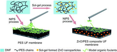
Ultrafiltration (UF) is an emerging membrane-based water separation process with potential application in drinking water treatment and for wastewater reuse. Nevertheless, membrane fouling decreases membrane performance and increases the frequency and cost of chemical cleaning. In this work, we present a method for loading ZnO nanoparticles into a polyethersulfone (PES) UF membrane to improve its fouling resistance. ZnO nanoparticles were synthesized with a sol–gel process using cost-effective precursors, resulting in particles with an average radius of 10 nm and ZnO content between 0.25 and 0.75 wt%. The hydrophilicity of the membrane surface was improved by the integration of ZnO nanoparticles, leading to a reduction in membrane contact angle (75.5 to 62.6°) and an increase in permeability (46.4 to 365.8 L m−2 h−1). Sodium alginate (SA), bovine serum albumin (BSA) and humic acid (HA) were chosen as model organic foulants to investigate fouling behavior of the fabricated membranes. Reduced fouling was conspicuously observed for ZnO/PES composite membranes compared to control membranes in all fouling cases. In order to better understand the fouling mechanism, atomic force microscopy (AFM) was used to quantify the intermolecular adhesion forces between the foulant and the clean or fouled membrane. Lower adhesion forces were observed for the modified membranes, indicating that the addition of sol–gel formed ZnO nanoparticles endows the PES UF membrane with an improved antifouling performance.

1. Introduction

Membrane-based processes hold significant promise in addressing the global challenge of water scarcity.1 Ultrafiltration (UF), an emerging membrane technology that utilizes hydraulic pressure to drive water permeation, is the subject of significant current interest due to its advantages of low energy consumption, high separation efficiency and the absence of any need for chemical pre-preparation.2–4 Unfortunately, due to the inherently hydrophobic nature of polymeric membranes, organics, colloids and micro-organisms in feed solutions are prone to adsorb onto membrane surfaces and in pore walls during the operation, leading to membrane fouling. Fouling reduces the flux and diminishes the functionalities of membranes, sequentially increasing the energy demand and shortening membrane life.5,6 Therefore, hydrophilic modification for polymeric membranes is a pressing demand in overcoming these problems and tailoring the UF membrane with a desirable performance.

To address these challenges, several strategies have been reported to improve the organic fouling resistance of UF membranes, many of which involve the inclusion of inorganic fillers into polymeric membranes to prepare mixed matrix membranes (MMMs).7,8 Inorganic nanoparticles have been usually adopted as fillers to form MMMs due to their hydrophilicity, large specific surface area, pore channels and other functional characters.9–11 The inorganic nanoparticles can provide specific functionalities to polymeric matrix, while retaining the intrinsic separation performance of the bare membrane. Generally, two main approaches have been pursued in incorporating inorganic nanoparticles into MMMs:10 (1) the physical blending method,12,13 whereby commercial or pre-prepared nanoparticles are physical dispersed into the polymeric matrix; and (2) the sol–gel route,14,15 where the precursor of nanoparticles are mixed at the molecular level in a casting solution. Although physical blending method provides a straightforward route to allow an independent filler phase synthesis procedure regardless of the membrane formation condition, it has some intrinsic shortcomings. Agglomeration of nanoparticles can be one of the most significant defects, leading to a compromised antifouling performance by changing parameters such as membrane topography and hydrophilicity.16 Compared to the physical blending method, the sol–gel process is beneficial to improving filler dispersion and polymer–filler contact by combining the formation of nanoparticles with the traditional immersion precipitation process, showing obvious advantages in suppressing nanoparticles agglomeration.17 Moreover, the viscous hybrid sol allows the direct preparation of composite membranes for diverse shapes of membrane modules. Up to now, a variety of nanoparticles have been introduced to modify polymeric membranes with the sol–gel route, such as TiO2,18 SiO2,19 Al species,16 and ZrO2.20 Owing to the multiple sol–gel precursors, the produced nanoparticles can absorb hydroxyl or amino groups on the surface, endowing the membrane with a higher hydrophilicity and antifouling propensity.10 However, these precursors have some disadvantages such as a potentially high cost, flammability and toxicity. In many cases, these precursors are very sensitive to moisture and one cannot control the hydrolysis reaction.16 Therefore, safe, economical and ecofriendly sol–gel precursors or obtained nanoparticles is essential to ensure the preparation of MMMs with the sol–gel route.

Zinc oxide (ZnO) nanoparticles, which are completely hydrophilic, have drawn attention over recent years due to their extensive applications in antibacterial creams, self-cleaning glass and biofouling-resistant membranes.21 With one-fourth the cost, ZnO nanoparticles is clearly more economical than TiO2 and Al2O3 nanoparticles.22 In fact, commercial ZnO nanoparticles have been immobilized in a variety of polymeric matrix with physical blending method. The fabricated composite membranes exhibited promising filtration properties, an improved hydrophilicity and a good resistance against organic foulants.22,23 Currently, the sol–gel process has been reported to produce ZnO nanoparticles in a highly controlled way. Inorganic salts like nitrates and chlorides can be applied as precursors to provide a simple procedure in preparing ZnO nanoparticles with the sol–gel route.24,25 This facile method makes it possible to use cost-effective precursors and nanoparticles to tailor the performance of MMMs. Recently, submicron ZnO particles have been fabricated with solvothermal reaction to improve the filtration performance of PES UF membrane.26 However, few studies report the preparation of PES UF membranes containing sol–gel formed ZnO nanoparticles. A systematic mechanistic understanding on the fouling behavior of ZnO/PES UF membrane is lacking as well.

In this study, a PES UF membrane embedded with sol–gel formed ZnO nanoparticles via non-solvent induced phase separation (NIPS) was fabricated. The effect of different amounts of ZnO nanoparticles on the microstructure, hydrophilicity and filtration performance was investigated. The antifouling property of the resultant membranes was evaluated using sodium alginate (SA), humic acid (HA) and bovine serum albumin (BSA) as model organic foulants. Filtration tests with individual foulants were conducted to identify the antifouling mechanism of ZnO/PES composite membranes. Finally, atomic force microscopy (AFM) was used to further analyze the membrane fouling behavior and antifouling mechanism by measuring foulant–membrane and foulant–foulant interfacial forces.

2. Experimental

2.1. Preparation of ZnO nanoparticles sol

The procedure for preparation of ZnO nanoparticles sol is based on the report of Yao et al.27 with modification. In this work, inorganic salts, zinc nitrate hexahydrate (Zn(NO3)2·6H2O, AR) was used as precursor of ZnO nanoparticles. The hydrolysis of Zn(NO3)2 occurred first in N,N-dimethylformamide (DMF; >99%, reagent). Then the following polymerization step triggered the formation of HO–Zn+ under heating condition. Next, Zn–O–Zn bonds formed with the dehydration among the intermediates at the condensation stage. In this process, polyvinylpyrrolidone (PVP, K-30) was introduced in DMF, which tailored the morphology and improved the dispersity of ZnO nanoparticles in the nucleation and growth stage. The detailed preparation procedure of ZnO nanoparticles is shown in ESI.

2.2. Preparation of PES hybrid UF membrane

Non-solvent induced phase separation (NIPS) was applied for the preparation of a PES UF membrane. 15 g polyethersulfone (PES, Ultranson E6020P with Mw = 58[thin space (1/6-em)]000 g mol−1) and 3.4 g PVP were added into ZnO nanoparticles sol to form mixed solution. Subsequently, the polymer solution was subjected to mechanical stirring at 60 °C for 12 h to obtain a uniform and homogeneous casting solution. The obtained casting solution was kept in a glass bottle at room temperature for degassing for 12 h to prevent defects in the membrane. Then, the solution was cast using an automated film applicator (MRX-TM300, Shenzhen, China) with a gap of 350 μm on a glass plate substrate. Casting speed was adjusted by a motorized film applicator to 30 mm s−1. After 20 s evaporation time in air, the glass plate was immediately immersed in the coagulation bath (deionized water 75 v% and isopropanol 25 v%) to induce phase separation. After 15 min, the membrane was transferred to a fresh deionized water bath and stored overnight to allow for complete solvent removal. The fabricated ZnO/PES UF membranes were designated as PES-X, where X corresponded to the ZnO content (Table S1 in ESI). Deionized water used in all experiments was supplied by a Millipore Elix Water Purification system.

2.3. Membrane characterization

The structural characteristics of the membranes were investigated using the following parameters: morphology, pore size, overall porosity, surface roughness and hydrophilicity. The presence of ZnO nanoparticles in MMMs was confirmed by X-ray photoelectron spectroscopy (XPS, PHI QUANTERA, USA) and thermo gravimetric analysis (TGA, SDT Q600 Simultaneous DSC-TGA, TA, USA). Moreover, the filtration performance of the membranes was also evaluated by measuring the permeability, rejection and molecular weight cutoff (MWCO). The details are displayed in ESI.

2.4. Model foulants and synthetic foulant solutions

The model organic foulants chosen to represent proteins, polysaccharides and natural organic matter were bovine serum albumin (BSA, Sinopharm Chemical Reagent Co., Ltd), sodium alginate (SA, Sigma-Aldrich) and humic acid (HA, Sigma-Aldrich). These three types of organic foulants were all received in powder form. The data of these foulants are shown in ESI. Stock solutions for BSA, SA and HA were prepared by dissolving the foulant in deionized water. All the stock solutions were filtrated with 0.45 μm microfiltration membranes to remove particles and insoluble matters. Afterwards, the obtained solutions were collected and stored at 4 °C prior to tests.

Synthetic foulant solutions, containing one individual foulant or a foulant mixture, were prepared on the basis of a previous study,22 as presented in Table S2 (see ESI). Water hardness was provided by addition of CaCl2 and MgCl2. NaCl was added to adjust ionic strength. Solution pH was buffered with NaHCO3. All chemicals were used as received. The molecular size distributions of the model foulants in the pre-filtered solutions were characterized using a ZetaPlus Zeta Potential Analyzer (Brookhaven Instruments Corporation, USA).

2.5. Evaluation of antifouling performance

The filtration experiments were conducted using the dead-end filtration system with synthetic foulant solutions to investigate the antifouling behavior of pristine and hybrid membranes. For filtrations with the synthetic solutions (mixture, SA, HA, BSA), both deionized water and foulant-free solution (Table S2 in ESI) were used to evaluate membrane fluxes (i.e., pure water flux, J, and the foulant-free solution flux, JS). Furthermore, three sequential cycles of dead-end filtration were carried out to further assess the long-term fouling reversibility of the resultant membranes with mixture synthetic solutions. The specific evaluation processes are given in ESI.

2.6. AFM adhesion force measurements

The adhesion forces of foulant–membrane and foulant–foulant were measured with an atomic force microscope (AFM, Dimension Icon, Bruker, Germany) under contact mode. A commercial V-shaped SiN probe (spring constant of 0.06 N m−1, Novascan Technologies, Inc., USA) modified with a 5.0 μm carboxyl-SiO2 particle on the end of the cantilever was used to detect the adhesion forces. Before the AFM analysis, the probe was coated with foulants by soaking it in organic foulant solution (2000 mg L−1 SA, HA, or BSA) for at least 24 h at 4 °C to prevent organic degradation. During this step, the organic molecules were adsorbed onto the surface of carboxyl-SiO2 particle.

The AFM adhesion force measurements were performed in a fluid cell, following the procedures described by Li and Elimelech.28 The foulant–membrane forces were measured after injecting into the fluid cell the foulant-free solution that was used as testing solution. To measure foulant–foulant intermolecular forces, 20 mg L−1 of organic foulant was introduced into the fluid cell and deposited to the membrane surface. For each force measurement experiment, the test solution was left to equilibrate with the resultant membrane for 30–45 min. Force measurements were performed at five different locations on the membrane, with more than 10 force measurements collected at each location. Only the retracting (pull-off) force curves were processed and converted to obtain the adhesion force.

3. Results and discussion

3.1. Characterization of synthetic ZnO nanoparticles

The formation of ZnO nanoparticles was represented by visually comparing the photographs of Zn2+/DMF solution and ZnO nanoparticles sol. The Zn2+/DMF solution was prepared by simply dissolving Zn(NO3)2·6H2O and PVP into DMF without following heating step. As shown in Fig. S1(A) (see ESI), the color of the solution in the right tube is transparent oyster white, indicating the formation of a ZnO nanoparticles sol. TEM was used to investigate the particle size; the result is shown in Fig. S1(B). ZnO nanoparticles were observed to have the form of black spots with an average size of 10 nm, which suggests that there is no agglomeration during the preparation of ZnO nanoparticles via the sol–gel process.

3.2. Morphology and structure of PES hybrid membrane

In order to investigate the effect of ZnO nanoparticles on the microstructure of the membranes, FE-SEM images of both top surfaces and cross sections of prepared PES membranes were made (Fig. 1). All the top-view images exhibit homogeneous porous surfaces with pore size of around 15 nm. The cross sections of pristine and composite membranes have the same anisotropic structure with a thin selective layer on a macroporous substructure through the main part of membranes (Fig. 1, column III), indicating that the immobilization of ZnO nanoparticles did not affect the morphologies of cross sections. However, the images of top surface suggest that by increasing the nanoparticles loading, the surface morphologies of resultant membranes changed from a surface with tortuous pores to a relatively flat surface with straight circular pores. In addition, a gradual increase in the pore size and pore density was observed. Corresponding AFM images also demonstrated significantly bigger pore size and higher pore density emerged on the top surface (Fig. 1, column I). The demixing process kinetics of casting solutions significantly influence the final morphology of the membranes.29 Through the sol–gel process –OH groups are present on the surface of ZnO nanoparticles. These hydrophilic surface groups may facilitate the exchange rate of solvent and non-solvent, increasing the demixing rate. The incorporation of ZnO nanoparticles into the casting solution decreases the interaction between polymer and solvent molecules, which led to an acceleration of NIPS process. Hence, the larger pores are formed on the surface of composite membranes.
image file: c5ra05783c-f1.tif
Fig. 1 FE-SEM and AFM images of top surfaces (column I, II) and FE-SEM images of cross sections (column III) for PES-0 (A–C), PES-0.25 (D–F), PES-0.5 (G–I) and PES-0.75 (J–L).

The pore size distribution of pure and hybrid membrane is presented in Fig. S2 (see ESI). It was observed that the addition of different amounts of ZnO nanoparticles varies the pore size distribution of PES UF membranes between 13.4 nm and 18.5 nm. The mean pore size and the maximum pore size are given in Table 1. The pore size of the resultant membranes increases with the incorporation of ZnO nanoparticles into the polymeric matrix, which is in agreement with the analysis of the membrane morphology. The PES-0.75 membrane showed the highest mean pore size at 16.3 nm, compared to the pure PES membrane which has a mean pore size of 14.7 nm. In addition, a similar tendency was obtained for the porosity (ε) (Table 1). The porosity of composite membranes increases with the increase of the content of ZnO nanoparticles and reaches a peak at 85.7% for the PES-0.75 membrane. These results can be ascribed to the accelerated demixing process leading to the formation of larger pores during the NIPS process, as discussed above.

Table 1 Different performance parameters for neat and hybrid membranes
  ε (%) Contact angle (°) Pore size
rm (nm) rmax (nm)
PES-0 82.7 ± 0.8 75.5 ± 0.6 14.66 15.45
PES-0.25 83.7 ± 0.6 70.8 ± 0.5 14.81 15.56
PES-0.5 85.1 ± 0.9 66.9 ± 0.8 16.08 16.71
PES-0.75 85.7 ± 1.0 62.6 ± 0.3 16.26 16.89


3.3. Filtration performance

The permeability and BSA rejection for pristine and ZnO/PES hybrid membranes were evaluated using a dead-end filtration apparatus (Fig. 2). It was found that the permeability of ZnO/PES composite membranes increases with the increase of ZnO amount. A minimum value of 46.4 L m−2 h−1 of pure water was measured for the pristine PES membrane and a maximum value of 365.8 L m−2 h−1 for the PES-0.75 membrane, indicating that the membrane hydrophilicity was improved greatly by the incorporation of ZnO nanoparticles, which matched the results of contact angle test shown in Table 1. The steady increase in pure water fluxes of hybrid membranes with increasing the ZnO nanoparticles amount can be explained by a combination of several factors. Firstly, the increase of membrane hydrophilicity could attract water molecules inside the membrane matrix and promote them to pass through the membrane and accordingly enhance the permeability.30 Secondly, the interfacial gaps between ZnO nanoparticles and the PES polymer matrix provide additional water channels to increase membrane filtration permeability under transmembrane pressure.31 Thirdly, the PES chains packing and linking are disrupted and/or damaged by the introduction of ZnO nanoparticles, which results in the formation of polymer free volume, promoting water permeability.32 Furthermore, the increase of pore size and porosity also has a positive influence on the permeability of the resultant membranes. However, the rejections of prepared membranes to BSA only exhibited a slight fluctuation with the increase of the amount of ZnO nanoparticles. The small variation of BSA rejections suggested that the immobilized ZnO nanoparticles did not greatly impair the protein separation performance of the membrane.
image file: c5ra05783c-f2.tif
Fig. 2 The pure water flux and BSA rejection of membranes with different ZnO nanoparticles contents.

3.4. Organic fouling of fabricated membranes

The effect of ZnO nanoparticles on the antifouling performance of hybrid membrane was investigated in the presence of a mixture of divalent cations (Ca2+, Mg2+) and organic foulants (SA, HA, BSA). Filtration experiments were carried out for 70 min at 0.1 MPa and were followed by a ‘physical’ cleaning in the absence of calcium ions. Among the different filtration stages, few minutes were needed to change the filtration solution and clean the filtration pipeline. In following discussion, the decline and recovery of water flux are used as heuristic parameters to describe membrane fouling and cleaning behavior, respectively.

The membranes were first challenged with mixed foulants (Table S2 in ESI). At the very beginning of the fouling stage (Fig. 3A), a much more severe flux decline for pure PES membrane was observed (to ∼40% of the initial flux) due to instant fouling and concentration polarization. After the ‘physical’ cleaning, only a slight increase (from ∼23% to ∼34%) was observed for both J and JS, indicating a poor antifouling effect. In contrast, the fouling rate and the fouling extent of ZnO/PES membranes decreased drastically. The PES-0.75 membrane maintained ∼75% of its initial flux after the instant flux decline, and then attained a plateau at ∼28% as foulants accumulated at the surface. Moreover, after the simple ‘physical’ cleaning operation, the flux recovery of PES hybrid membranes increased from ∼55% to more than 83% of the initial water flux with the increase of the amount of ZnO nanoparticles, demonstrating the antifouling effect of ZnO/PES membranes.


image file: c5ra05783c-f3.tif
Fig. 3 Antifouling performance of the pure and hybrid membranes in filtration runs with different foulant solutions: (A) mixture of sodium alginate (SA), humic acid (HA) and bovine serum albumin (BSA); (B) SA; (C) HA and (D) BSA.

The membranes were also challenged, separately, with individual foulant (SA, HA, BSA, Table S2 in ESI) to study the fouling behavior of the membranes. The pure PES membrane exhibited a poor antifouling performance in all cases (Fig. 3B–D). Similar flux decline curves were observed in the fouling stages, and no significant flux increase was obtained after the ‘physical’ cleaning. For ZnO/PES membranes, a decline in water flux was also observed in the filtration runs with SA solution (Fig. 3B). This observation is attributed to complexation and bridging, which alginate molecules experience in the presence of calcium ions, resulting in the formation of a cross-linked alginate gel layer on the membrane surface.33 However, ZnO/PES membranes exhibited a conspicuous antifouling nature, where the hybrid membrane retained a much higher flux during the fouling, and achieved an about 90% flux recovery after cleaning (Fig. 3B). These results correspond well with the hydrophilic nature of the ZnO/PES membrane. As described above, the addition of ZnO nanoparticles improved the hydrophilicity of PES hybrid membrane and immobilized water molecules in the vicinity of PES membranes. The hydrated layers hinder the alginate molecules to form firm bonds that contribute to the organic fouling. Furthermore, foulants are likely to be absorbed in the valleys of membrane with coarser surfaces, resulting in clogging of the valleys.34 The addition of hydrophilic ZnO nanoparticles decreased the roughness of the PES membrane, as evidenced by the AFM results, which further mitigated the organic fouling.

The hybrid membrane also performed well in the filtration runs with HA and BSA. In the fouling stage, the adsorption of HA or BSA caused a gradual flux decline (Fig. 3C and D). Nevertheless, limited recovery of water flux was observed for ZnO/PES membranes fouled by HA or BSA under the examined conditions. The different antifouling behavior with SA compared to HA and BSA is attributed to two main reasons. First, alginate is more hydrophilic than HA and BSA,35 which dramatically decreases the adsorption tendency of alginate on the membrane surface, especially for the case of the hydrophilic membrane. Consequently, the current ‘physical’ cleaning method was able to rinse off the SA on the membrane surface, but might not clean off the HA or BSA fouling. Second, due to the complexation and bridging mechanism, larger SA molecules were formed in the presence of calcium ions.36 As shown in Fig. S7, the SA has an average diameter of ∼159 nm, which was larger than that of the HA (average diameter of ∼135 nm), and much larger than that of the BSA (average diameter of ∼25.2 nm). The average diameters of SA, HA and BSA in the salt solution is obviously larger than that of single foulant molecule. This phenomenon can be attributed to the aggregation of foulant molecules under the effect of Ca2+ and Mg2+.36–38 The large SA molecules will aggregate or form gel layer on the surface of the membrane. The sparse and loose layer of SA formed during fouling can be easily broken and removed by a simple physical cleaning with solutions that do not contain calcium ions. In contrast to alginate, a considerable portion of HA and BSA would penetrate the selective membrane skin-layer and accumulate within the membrane matrix. This internal fouling was irreversible with the current surface cleaning strategy. Therefore, the cleaning efficiency for the individual HA and BSA fouling lower than that for the individual SA fouling (Fig. 4).


image file: c5ra05783c-f4.tif
Fig. 4 Comparison of fouling reversibility between fouled pure and hybrid membranes in filtration runs with different foulant solutions: mixture, SA, HA and BSA.

In order to further elucidate the antifouling performance of ZnO/PES membranes after a long period fouling operation, a three-step filtration operation was conducted with mixed foulants solutions (Table S2 in ESI). The time-dependent flux curves for the resultant membranes are shown in Fig. S8 (see ESI) and the calculated flux recovery data are summarized in Table 2. The ZnO/PES composite membranes experienced a lower overall flux decline compared to control membranes, which indicates a higher resistance to organic fouling. During the first cycle, R of the four membranes increased from 33.2%, 52.5%, 63.1% to 69.7% corresponding to the different amount of ZnO nanoparticles. The control membrane is prone to adsorb foulants and these foulants give rise to a low flux recovery. The more hydrophilic the membrane was, the less the flux decreased. From the data listed in Table 2, this high water flux recovery was consistently obtained in the further two filtration cycles, suggesting that the antifouling characteristics of ZnO/PES membrane are stable for a long period of operation under fouling conditions. Moreover, the decline of flux recovery for PES-0.25 membrane was marked during the three-step filtration operation, which was more obvious than that of pure PES membrane and the other composite membranes. As shown in Table 1, the addition of ZnO nanoparticles resulted in the increase of overall porosity. Foulant molecular were inclined to adsorb into the membrane matrix, which had a negative effect on the flux recovery. However, with the increase of ZnO amount, the positive effect on high flux recovery, deriving from the improved hydrophilicity, outstripped the counter effect of increased porosity. The trade-off relationship between hydrophilicity and porosity trigger the different rangeability for pure PES and composite membranes.

Table 2 Calculated water flux recovery of the three filtration cycles for different membranes
Cycle Flux recovery (%)
PES-0 PES-0.25 PES-0.5 PES-0.75
I 33.2 52.5 63.1 69.7
II 29.2 43.7 62.5 68.5
III 26.0 39.6 59.7 66.1


3.5. Understanding fouling behavior for ZnO/PES membranes

To further understand the surface properties responsible for the different fouling behavior of the resultant membranes, AFM force measurements were used to characterize the foulant–membrane and foulant–foulant interactions. AFM has been successfully employed to quantify the short-range intermolecular forces that govern the fouling behavior of surfaces.5,28,33,34,39 Fig. 5 presents the frequency distribution of foulant–membrane and foulant–foulant adhesion forces, respectively. Foulant–membrane force measurements provide information about the initial attachment of foulant molecules to the membrane surface, while foulant–foulant interaction presents the strength of adhesion of already adsorbed molecules on the surface.
image file: c5ra05783c-f5.tif
Fig. 5 Adhesion force measurements of (A) foulant–membrane and (B) foulant–foulant interaction by AFM contact mode. The different plots refer to interactions between membrane surfaces (PES-0 in red, PES-0.75 in green) and model foulants: (a) alginate, (b) BSA, (c) HA. Note the graphs are plotted with a different scale for the x axis.

In all cases, the adhesion force distribution measured with the pure PES membranes are shifted towards more negative values, indicating greater adhesion forces compared to the ZnO/PES hybrid membrane. The average adhesion forces for the pure PES membranes were about 2 times the values observed for the composite membranes. Fig. 5(A) shows that the adhesion forces of foulant–membrane interactions for the three organic foulants increase in the following order: SA-membrane < BSA-membrane < HA-membrane. Considering the filtration curves of SA-, HA- and BSA-fouled membranes in the initial filtration stage (Fig. 3), it is clear that the stronger the adhesion force of the foulant–membrane, the more severe is the flux decline in the initial filtration stage. This result confirms that the foulant–membrane interaction measurements can provide useful information to predict the flux decline rate and extent of membrane fouling in the initial stage.

As shown in Fig. 5A(a), the SA-membrane adhesion forces of the pure PES membrane are distributed over a much wider range. This result can be attributed to the more heterogeneous surface of the pure PES membrane (Fig. S3 in ESI). However, this fouling phenomenon was thwarted for the ZnO/PES membrane, for which the adhesion forces of the composite membrane were distributed in a more compact fashion and centered at low adhesion forces values (average force of ∼−0.52 mN m−1). This is because the addition of sol–gel formed ZnO nanoparticles ameliorates the hydrophilicity and endows the membrane with smoother surface. A more representative system to understand SA-membrane interactions during real operation is obtained by foulant–foulant interaction forces measurements. Longer rupture distances and a wider force distribution were observed than in the case of HA and BSA during the retraction of the probe from the membrane surface (Fig. 5B(a)), consistent with the bridging mechanism. Once a layer of SA has formed at the surface, bridging can occur among the probe, the alginate film at the surface and alginate molecules in solutions, leading to the continuous formation and growth of a cross-linked alginate gel layer on the membrane surface. Therefore, in the case of SA, bridging and foulant–foulant interaction controlled the fouling behavior.

It is noteworthy that the BSA-membrane adhesion force for pure PES membrane was found to shift towards more negative values than in the case of SA, which can be ascribed to the different fouling mechanism and foulant nature. Due to the van der Waals and electrostatic interaction, protein molecules are inclined to adsorb on the hydrophobic surface.40 Considering that BSA is more hydrophobic than SA, larger adhesion forces can be obtained during the foulant–membrane measurement for the pure PES membrane (Fig. 5A(b)). However, for the ZnO/PES composite membrane, lower BSA fouling has been observed due to the inability of protein molecules to displace the bound hydration layer and adsorb on the surface. Similar results also can be observed in the case of HA (Fig. 5A(c)). It is worth noting that the order of adhesion forces for foulant–foulant measurements (Fig. 5B) shows a direct correlation with the variation characteristics of the corresponding pseudostable flux (Fig. 3). The higher the adhesion force of the foulant–foulant, the lower the pseudostable flux. These results confirm that the pseudostable flux can be predicted by analyzing the foulant–foulant adhesion forces.

4. Conclusions

A facile method for fabricating antifouling and high-flux ultrafiltration membrane was developed enabled by ZnO nanoparticles. The strategy combined the cost-effective sol–gel preparative technique of ZnO nanoparticles with the traditional immersion precipitation process. The incorporation of sol–gel formed ZnO nanoparticles tailored the microstructure and hydrophilicity, rendering the composite membrane with improved permeability over the neat PES membrane. Filtration experiments with individual model organic foulants (i.e. SA, HA and BSA) in the presence of divalent cations (i.e. Ca2+ and Mg2+) confirmed the antifouling performance of ZnO/PES composite membranes. The reliability and durability were demonstrated with three-step filtration operation using combined foulants. Moreover, the membrane fouling behavior was systematically investigated by measuring the foulant–membrane and foulant–foulant adhesion forces. The results confirmed the hydrophilic modification and foulant nature play an important role in controlling membrane fouling. AFM force measurement can provide useful information to predict membrane fouling behavior.

Acknowledgements

This work was financially supported by the National Natural Science Foundation of China (Grant no. 51278247) and the priority academic program development of Jiangsu higher education institutions.

References

  1. M. A. Shannon, P. W. Bohn, M. Elimelech, J. G. Georgiadis, B. J. Mariñas and A. M. Mayes, Nature, 2008, 452, 301–310 CrossRef CAS PubMed.
  2. L. Wang, R. Miao, X. Wang, Y. Lv, X. Meng, Y. Yang, D. Huang, L. Feng, Z. Liu and K. Ju, Environ. Sci. Technol., 2013, 47, 3708–3714 CrossRef CAS PubMed.
  3. M. M. Pendergast and E. M. V. Hoek, Energy Environ. Sci., 2011, 4, 1946–1971 CAS.
  4. M. G. Buonomenna, RSC Adv., 2013, 3, 5694–5740 RSC.
  5. A. Asatekin, S. Kang, M. Elimelech and A. M. Mayes, J. Membr. Sci., 2007, 298, 136–146 CrossRef CAS PubMed.
  6. S. Liang, Y. Kang, A. Tiraferri, E. P. Giannelis, X. Huang and M. Elimelech, ACS Appl. Mater. Interfaces, 2013, 5, 6694–6703 CAS.
  7. P. Wang, J. Ma, Z. Wang, F. Shi and Q. Liu, Langmuir, 2012, 28, 4776–4786 CrossRef CAS PubMed.
  8. C. Zhao, J. Xue, F. Ran and S. Sun, Prog. Mater. Sci., 2013, 58, 76–150 CrossRef CAS PubMed.
  9. L. Y. Ng, A. W. Mohammad, C. P. Leo and N. Hilal, Desalination, 2013, 308, 15–33 CrossRef CAS PubMed.
  10. Y. Li, G. He, S. Wang, S. Yu, F. Pan, H. Wu and Z. Jiang, J. Mater. Chem. A, 2013, 1, 10058–10077 CAS.
  11. J. Kim and B. Van der Bruggen, Environ. Pollut., 2010, 158, 2335–2349 CrossRef CAS PubMed.
  12. J. Dasgupta, S. Chakraborty, J. Sikder, R. Kumar, D. Pal, S. Curcio and E. Drioli, Sep. Purif. Technol., 2014, 133, 55–68 CrossRef CAS PubMed.
  13. R. Jamshidi Gohari, E. Halakoo, W. J. Lau, M. A. Kassim, T. Matsuura and A. F. Ismail, RSC Adv., 2014, 4, 17587–17596 RSC.
  14. F. Zhang, W. Zhang, Y. Yu, B. Deng, J. Li and J. Jin, J. Membr. Sci., 2013, 432, 25–32 CrossRef CAS PubMed.
  15. K. Li, G. Ye, J. Pan, H. Zhang and M. Pan, J. Membr. Sci., 2010, 347, 26–31 CrossRef CAS PubMed.
  16. R. Pang, J. Li, K. Wei, X. Sun, J. Shen, W. Han and L. Wang, J. Colloid Interface Sci., 2011, 364, 373–378 CrossRef CAS PubMed.
  17. C. Laberty-Robert, K. Vallé, F. Pereira and C. Sanchez, Chem. Soc. Rev., 2011, 40, 961–1005 RSC.
  18. X. Li, X. Fang, R. Pang, J. Li, X. Sun, J. Shen, W. Han and L. Wang, J. Membr. Sci., 2014, 467, 226–235 CrossRef CAS PubMed.
  19. L.-Y. Yu, Z.-L. Xu, H.-M. Shen and H. Yang, J. Membr. Sci., 2009, 337, 257–265 CrossRef CAS PubMed.
  20. R. Pang, X. Li, J. Li, Z. Lu, X. Sun and L. Wang, Desalination, 2014, 332, 60–66 CrossRef CAS PubMed.
  21. Q. Li, S. Mahendra, D. Y. Lyon, L. Brunet, M. V. Liga, D. Li and P. J. J. Alvarez, Water Res., 2008, 42, 4591–4602 CrossRef CAS PubMed.
  22. S. Liang, K. Xiao, Y. Mo and X. Huang, J. Membr. Sci., 2012, 394–395, 184–192 CrossRef CAS PubMed.
  23. S. Balta, A. Sotto, P. Luis, L. Benea, B. Van der Bruggen and J. Kim, J. Membr. Sci., 2012, 389, 155–161 CrossRef CAS PubMed.
  24. L. Znaidi, Mater. Sci. Eng., B, 2010, 174, 18–30 CrossRef CAS PubMed.
  25. A. Moezzi, A. M. McDonagh and M. B. Cortie, Chem. Eng. J., 2012, 185–186, 1–22 CrossRef CAS PubMed.
  26. S. Zhao, W. Yan, M. Shi, Z. Wang, J. Wang and S. Wang, J. Membr. Sci., 2015, 478, 105–116 CrossRef CAS PubMed.
  27. K. X. Yao and H. C. Zeng, J. Phys. Chem. C, 2007, 111, 13301–13308 CAS.
  28. Q. L. Li and M. Elimelech, Environ. Sci. Technol., 2004, 38, 4683–4693 CrossRef CAS.
  29. X. Fang, J. Li, X. Li, X. Sun, J. Shen, W. Han and L. Wang, J. Membr. Sci., 2015, 476, 216–223 CrossRef CAS PubMed.
  30. X. Li, R. Pang, J. Li, X. Sun, J. Shen, W. Han and L. Wang, Desalination, 2013, 324, 48–56 CrossRef CAS PubMed.
  31. H. Ma, C. Burger, B. S. Hsiao and B. Chu, ACS Macro Lett., 2012, 1, 723–726 CrossRef CAS.
  32. H. Wu, B. Tang and P. Wu, J. Phys. Chem. C, 2012, 116, 2246–2252 CAS.
  33. B. Mi and M. Elimelech, J. Membr. Sci., 2010, 348, 337–345 CrossRef CAS PubMed.
  34. E. M. Vrijenhoek, S. Hong and M. Elimelech, J. Membr. Sci., 2001, 188, 115–128 CrossRef CAS.
  35. N. Subhi, A. R. D. Verliefde, V. Chen and P. Le-Clech, J. Membr. Sci., 2012, 403–404, 32–40 CrossRef CAS PubMed.
  36. H.-C. Kim and B. A. Dempsey, J. Membr. Sci., 2013, 428, 190–197 CrossRef CAS PubMed.
  37. K. Katsoufidou, S. Yiantsios and A. Karabelas, J. Membr. Sci., 2005, 266, 40–50 CrossRef CAS PubMed.
  38. T. Nicolai, Biomacromolecules, 2005, 6, 2157–2163 CrossRef PubMed.
  39. Y. Mo, A. Tiraferri, N. Y. Yip, A. Adout, X. Huang and M. Elimelech, Environ. Sci. Technol., 2012, 46, 13253–13261 CrossRef CAS PubMed.
  40. C. S. Gudipati, J. A. Finlay, J. A. Callow, M. E. Callow and K. L. Wooley, Langmuir, 2005, 21, 3044–3053 CrossRef CAS PubMed.

Footnote

Electronic supplementary information (ESI) available. See DOI: 10.1039/c5ra05783c

This journal is © The Royal Society of Chemistry 2015
Click here to see how this site uses Cookies. View our privacy policy here.