An effective dipping method for coating activated carbon catalyst on the cathode electrodes of microbial fuel cells

Zheng Ge and Zhen He*
Via Department of Civil and Environmental Engineering, Virginia Polytechnic Institute and State University, Blacksburg, VA 24061, USA. E-mail: zhenhe@vt.edu; Fax: +1-540-231-7916; Tel: +1-540-231-1346

Received 28th March 2015 , Accepted 16th April 2015

First published on 16th April 2015


Abstract

Activated carbon (AC) has been demonstrated as a promising cathode catalyst for microbial fuel cells (MFCs). A simple and effective dipping method was developed and examined for coating AC with better control of the loading rate than the commonly used brushing method.

Microbial fuel cells (MFCs) offer a promising bioelectrochemical approach for energy-efficient water/wastewater treatment and bioenergy recovery.1–3 MFCs rely on electrochemically-active bacteria to oxidize organic matter and respire with an electrode as an electron acceptor. This oxidation process in the anode produces electrons and protons, both of which move towards the cathode where the electrons and protons are consumed in the reduction reaction with a terminal electron acceptor, such as oxygen. Although oxygen is readily available in a large quantity (in the air), the oxygen reduction reaction (ORR) requires a catalyst to overcome the high energy potential. Many types of catalysts have been studied, including the most commonly used platinum (Pt) and a variety of other materials such as gold,4 cobalt,5 lead,6 iron,7 and activated carbon.8–13 In particular, activated carbon (AC) is very attractive as a cathode catalyst for MFCs, because of its low cost, a high specific surface area, and effective ORR catalysis;12 in addition, AC catalysts have been examined in MFCs for a long period of time and/or with actual wastewater, demonstrating its long-term stability.8,14 These findings suggest that AC can be used as an effective (in terms of both cost and performance) ORR catalyst for MFC application.

A widely used method for coating catalysts onto a cathode electrode is brushing, which applied the mixture of catalysts and a binding agent (e.g., Nafion or PTFE) to the surface of the electrode by using a brush.15,16 The brushing method is relatively simple and straightforward; however, it leaves a non-homogenous distribution of binder/catalyst mixture on the electrode, and may also cause catalyst loss to the brush (via adsorption). To prepare a large area of electrode, the brushing method will require a significant amount of manual operation. Recently, a rolling method was developed to fabricate the cathode electrodes for MFCs.10 Unlike the brushing method, the rolling method omits carbon cloth and instead uses stainless steel mesh as a supporting material. It is possible to have mess production of cathode electrode by using the rolling method; however, it should be noted that the rolling method requires special equipment for operation and the produced electrodes have not been used as widely as the one produced by the brushing method (though the rolling method is receiving increasing attention and interests). Other methods such as electrochemical deposition and spinning have not been applied to coat AC catalysts onto carbon cloth.

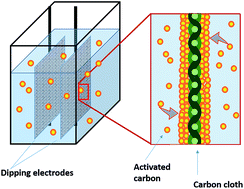
In this study, we have explored an alternative method for catalyst coating, the dipping method, which has been applied in fuel cell study.17 To examine its effectiveness for MFC application, the dipping method, linked to the heat treatment, was studied with mixture of AC powder (catalyst) and polytetrafluoroethylene (PTFE, binding agent). The prepared electrodes were analyzed using electrochemical techniques and examined in two types of MFCs. The effects of dipping concentration and frequency were investigated. The dipping method was compared with the brushing method for catalyst loading and electrode performance. It should be noted that the cathode electrode prepared by the dipping method is for the application of “wet cathode”, which is exposed in the air and rinsed by the catholyte to keep wet for conducting oxygen reduction. Unlike an air cathode that is applied to membrane-less MFCs, an ion exchange membrane is still used as a separator for a wet cathode, and different from a traditional cathode that is submersed in the catholyte, there is no a cathode compartment for a wet cathode.

A commonly designed loading rate of AC by using the brushing method is about 5 mg cm−2,8 but the exact amount of the AC coated on carbon-base materials (e.g., carbon cloth) is usually not quantified. By weighing the carbon cathode before and after coating, we found that the actual coated AC using the brushing method was 1.46 ± 0.55 mg cm−2, much lower than the designed loading of 5 mg cm−2, indicating that about 70% of AC powder was not loaded onto carbon cloth. By increasing the design loading rate to 10 mg cm−2 (which means more AC would be applied by the brush), the coated AC reached 2.45 ± 0.71 mg cm−2, which still had over 70% loss. The actual loading rate by using the brushing method could vary depending on the brush used, exact procedure, and skills of the person who performs it. The loss of AC could be due to the use of painting tools (painting brush) whose bristles absorbed a large amount of carbon powder/PTFE mixture. Another possible reason could be due to binding capability of PTFE. A higher concentration of PTFE is able to enhance the attachment of carbon powder with less loss but it also decreases the performance for catalytic reaction. To keep the testing condition consistent, the amount of PTFE (60%) was fixed at 2.5 mL per 100 mL ethanol for dipping, which was equivalent to the dosage applied for the brushing method (6.67 μL mg−1 AC).

The dipping method, on the other hand, has created more uniform distribution of AC with less variance. The actual AC loading by using the dipping method could be increased in two ways, repeated dipping to create multiple layers of AC catalysts and increasing the initial AC concentration in the mixture. Fig. 1 shows that both approaches could effectively improve the AC loading on carbon cloth. For example, at an initial AC input of 4 g per 100 mL ethanol, the actual AC loading on carbon cloth was 1.62 ± 0.15, 3.09 ± 0.21, and 4.60 ± 0.23 mg cm−2 for dipping 1, 2, and 3 times, respectively. When dipping one time, the coated AC on carbon cloth was increased from 0.56 ± 0.23 to 5.00 ± 0.88 mg cm−2 as the AC concentration was changed from 2 to 12 g per 100 mL ethanol. The concentration of 4 g per 100 mL ethanol had a same PTFE/AC ratio as that used in brushing method (6.67 μL mg−1), and it also resulted in a similar actual AC loading of 1.62 ± 0.15 mg cm−2 (one time dipping) to that by the brushing method (1.46 ± 0.59 mg cm−2) but with obviously less fluctuation. Thus, it is reasonable to conclude that, comparing with the brushing method, the dipping method is better for controlling or adjusting the actual loading of AC on carbon cloth.


image file: c5ra05543a-f1.tif
Fig. 1 The actual AC loading rates (Y axis) on the electrodes with different initial AC input of 2, 4, 8, and 12 g per 100 mL ethanol, and multiple dipping times.

To determine the relationship between carbon loading and electrochemical kinetics of ORR on the cathode electrode, Tafel plots were constructed to compare electrode reaction rate among the electrodes prepared in different ways. The mechanism of ORR with AC as a cathode catalyst has been investigated in the previous studies;18 thus, it is not the focus of this study and the Tafel results were used to compare the variance based on the numerical magnitude. The ORR on the cathode followed Tafel behavior when overpotential was larger than 0.118 V.19 Tafel equation relationship described by eqn (1)19 reveals that current (i) can change linearly as overpotential (η) and exchange current (i0) is involved in constant term as intercept when η is zero (equilibrium status).

 
image file: c5ra05543a-t1.tif(1)
i0 can be calculated and compared for its proportional relationship to reaction kinetics, and a high current value indicates a faster reaction rate with a lower overpotential demand, and vice versa.19 Because AC was the only catalyst involved and the loading of PTFE was fixed at 6.67 μL mg−1 AC, the main difference created by different dipping methods would be the amount of the coated AC and PTFE; the latter may affect the diffusion and adsorption of oxygen for ORR. As shown in Fig. 2A, the Tafel plots exhibited significant improvement by increasing the initial concentration of AC in the dipping mixture; the corresponding exchange current (i0) increased almost two-hundred times from 4 ± 3 (2 g) to 889 ± 149 μA (12 g AC), confirming that increasing the initial AC concentration in the dipping mixture could promote electrode reaction effectively. Apparently, the carbon loading is crucial that the more AC powder is per unit area cathode, the more active sites are for ORR. However, despite increased loading, repeated dipping did not show the expected improved performance; for example, the improvement at the low concentration of 2 g AC in 100 mL ethanol was limited, and for a high initial AC concentration (12 g AC), the extra dipping did not benefit the electron transfer notably (as shown in Fig. 2B).


image file: c5ra05543a-f2.tif
Fig. 2 Tafel plots of the cathode electrodes with different initial loading AC load (A) and different coating layers (CLs) by dipping (B).

Table 1 shows the exchange current extracted from the Tafel plots. The results confirm that a high initial AC concentration could effectively improve the reaction rate with high exchange current, whereas repeated dipping had limited improvement at low AC concentrations. At the initial AC concentration of 8 or 12 g per 100 mL ethanol, the second dipping resulted in improved exchanged current, but one more dipping (third dipping) actually decreased exchange current. For comparison, coating by brushing method with an initial designed loading rate of 5 mg cm−2 resulted in an exchange current of 54 ± 34 μA but coating more AC had limited improvement (∼20%) when the designed loading rate was doubled (10 mg cm−2).

Table 1 Exchange current generated with the cathode electrodes with different initial AC input and multiple dipping times
Coating methods Exchange current (μA)
2a 4a 8a 12a
a Initial concentration of AC in the dipping mixture (g per 100 mL ethanol).
One dipping 4 ± 3 57 ± 39 601 ± 424 889 ± 149
Twice dipping 4 ± 3 52 ± 5 669 ± 78 997 ± 96
Thrice dipping 4 ± 3 87 ± 81 142 ± 101 613 ± 230


The decreased exchange current with repeated dipping likely resulted from overly applied PTFE that could decrease active sites for catalytic reaction and oxygen transfer/adsorption. In addition, more AC layers would also decrease the diffusion of oxygen onto the surface of inner electrode material. Those results indicate that AC loading rate is not the only factor that controls the ORR; the distribution of AC particles and PTFE can also significantly influence ORR and thus current generation. Determining the optimal loading rate will be critical to avoiding overly applying catalysts and/or binding agent, thereby minimizing the amount of catalysts and associated cost.

The cathode electrodes prepared by the dipping method were further examined in a two-chamber H type MFC operated in a batch mode, as shown in Fig. 3. A cathode electrode prepared by the brushing method (designed AC loading rate of 5 mg cm−2) was used for comparison. Both power density and current production with the cathode prepared by one-time dipping (Fig. 3A and B) increased as the initial AC concentration changed from 2 g to 12 g per 100 mL ethanol, in a good agreement with the electrochemical tests. The electrodes prepared with low initial AC input (2 and 4 g) exhibited similar performance, but a higher AC input at 8 g increased the maximum power density by more than 25%, which was further improved by another 26% with 12 g. The minor difference in power output by the electrode between 2 and 4 g, despite doubled AC loading, indicates that the carbon amount might need to be maintained at a certain level for a linear improvement of electricity generation, but this needs further investigation. The cathode prepared by the brushing method resulted in a similar maximum power density as that of the dipping with 4 g AC (which had similar actual AC loading as the one by the brushing), but current generation after the maximum power output became much lower, indicating a lower kinetic activity in the high current zone.


image file: c5ra05543a-f3.tif
Fig. 3 Variation of voltage and power density with current density in the MFC containing cathode electrode prepared in different ways: (A and B) cathode electrode coated with different initial AC input and one prepared by the brushing method for comparison purpose; (C and D) cathode electrode coated by multiple dipping times. CL: coating layer.

The MFC tests showed some difference in electricity by the repeated dipping (Fig. 3C and D). At the low initial AC input of 2 g, the single and triple dipping led to better performance than dipping twice, in terms of both maximum power density and current generation. At the high initial AC input of 12 g, the double dipping generated the highest power density. Those results are close to those of Tafel plots with some deviation. However, it is clear that multiple dipping does not always improve ORR and electricity generation, although AC loading is increased. This indication is important to minimizing the use of AC catalyst and the time of electrode preparation.

To further demonstrate the effectiveness of the dipping method, the prepared electrodes were examined in a tubular MFC that had a wet cathode as previously reported.8,20 Three loading rates, prepared with three different initial AC inputs, 4, 12, and 18 g, were investigated. We could not conduct dipping with an initial AC input higher than 18 g, because carbon powder could not be well dispersed in the solvent. The initial AC input of 18 g could achieve actual loading of 14.5 mg cm−2 with one-time dipping. As shown in Fig. 4, both current density and total coulomb in the tubular MFC became higher at a higher AC loading rate. The current generation with the initial AC input of 18 g was more than twice that with 4 g, while the total charge production presented an approximate linear increment as the AC loading increased in the 12 hour batch tests. Those results confirm that the dipping method can deliver effective cathode electrodes for application in MFCs.


image file: c5ra05543a-f4.tif
Fig. 4 Current generation during batch operation (A) and the production of total charge in a batch (B) with different initial AC inputs in a tubular MFC.

Conclusions

To conclude, the dipping method is a promising alternative to coat AC catalysts on the MFC cathode electrode with several advantages. First, the dipping method is much easier and faster to be applied for preparing large-scale electrodes than the brushing method. By using the dipping method, a large piece of carbon cloth can be soaked in a tank containing the AC mixture for coating, while the brushing method requires intensive manpower or development of automatically-controlled brushes for coating. Second, the dipping method will have less loss of AC catalysts during the coating process, since the mixture can be reused with addition of AC catalysts, while the brushing method can result in significant loss of AC powder due to absorption, which also requires extensive cleaning after each coating. Third, the dipping method can deliver a more homogeneous surface coating, which is important to the use of the electrode material (avoiding the dead zones that are short of catalysts due to heterogeneous coating). Last, the dipping method can better control or manipulate the amount of catalyst coating on carbon cloth, which is critical to determining the precise amount of catalysts for large-scale MFC systems. Although some of the above advantages need to be verified with actual large-scale MFC development, the results in this work have demonstrated the effectiveness and promise of the dipping method, and encouraged further investigation.

Experimental

To perform the dipping method, 100 mL ethanol was gradually transferred into an air-tight container (150 mL) with selected amount of AC powder (2, 4, 8, or 12 g). Meanwhile, gentle stirring was provided for several seconds to mix and disperse the AC powder. Finally, 2.5 mL of 60% PTFE solution was added with stirring to form the slurry for dipping. The liquid mixture was stored in a 150 mL air-tight container. Dipping duration was fixed to 2 s for each piece of carbon cloth with the same size of 4 cm × 1 cm. Carbon cloth (PANEX 30PW03 at a cost of %44.4 m−2, Zoltek Corporation, St. Louis, MO, USA) was pretreated by acetone as described in a previous study.18 After dipping, the carbon cloth was dried and heated at 350 °C for 30 min. For comparison, multiple cathode electrodes were coated with AC by using the brushing method described as previous study18 with a design AC loading rate of 5 and 10 mg cm−2 (the actual AC loading was determined experimentally).

Electrochemical experiments were conducted as described in previous study21 in a 140 mL glass bottle with 130 mL of 50 mM PBS solution (2.65 g KH2PO4 and 5.35 g K2HPO4 per liter of tap water), where the cathode electrode served as a working electrode, a platinum mesh (002250 platinum gauze electrode 80 mesh, ALS Co., Ltd, Japan) served as a counter electrode, and an Ag/AgCl electrode (CH Instruments, Inc., Austin, TX, USA) functioned as a reference electrode. Air was pumped into the bottle for 30 min before each test to create O2-saturated condition. The electrode samples were submerged into 50 mM PBS solution for 30 min before any electrochemical tests. Tafel plots (scan rate: 1 mV s−1) were carried out by a potentiostat (Reference 600, Gamry Instruments, Warminster, PA, USA).

Two types of MFCs were used for the experiments. First, a two-chamber MFC as described in previous study18 was used for examining electricity generation with the prepared cathode electrodes. The polarization tests were conducted by using the Gamry potentiostat (scan rate: 0.2 mV s−1). The anode electrode was a 5 cm carbon brush with titanium wire collector. Second, to further examine the performance of dipping cathode, a 15 cm long tubular MFC was setup and operated with a wet cathode, which was coated with AC on carbon cloth; the cathode was exposed to air and rinsed with PBS instead of being submerged into the catholyte.8,20 The catholyte concentration was 50 mM PBS. Both two-chamber and tubular MFCs were inoculated with digested sludge from a local wastewater treatment facility (Peppers Ferry Regional Wastewater Treatment Plant, Radford, VA), and operated in a batch mode with the anolyte containing per liter of tap water: sodium acetate, 2 g; NH4Cl, 0.15 g; NaCl, 0.5 g; MgSO4, 0.015 g; CaCl2, 0.02 g; KH2PO4, 2.65 g; K2HPO4, 5.35 g; and trace element, 1 mL.22 The voltage of the MFC (across 100 ohm in the two-chamber MFC or 15 ohm in the tubular MFC) was recorded by multimeter (Model 2700; Keithley Instruments, Inc., OH, USA) with 5 min interval.

Acknowledgements

This project was financially supported by a grant from National Science Foundation (award # 1348424). The authors would like to thank Peppers Ferry Regional Wastewater Treatment Plant for providing digested sludge, and Dr Yaobin Lu (Virginia Tech) for his help with graph.

Notes and references

  1. W.-W. Li, H.-Q. Yu and Z. He, Energy Environ. Sci., 2014, 7, 911–924 CAS.
  2. B. E. Logan, B. Hamelers, R. Rozendal, U. Schröder, J. Keller, S. Freguia, P. Aelterman, W. Verstraete and K. Rabaey, Environ. Sci. Technol., 2006, 40, 5181–5192 CrossRef CAS.
  3. L. Xiao, Z. Ge, P. Kelly, F. Zhang and Z. He, Bioresour. Technol., 2014, 157, 77–83 CrossRef CAS PubMed.
  4. F. Kargi and S. Eker, J. Chem. Technol. Biotechnol., 2007, 82, 658–662 CrossRef CAS PubMed.
  5. F. Zhao, F. Harnisch, U. Schröder, F. Scholz, P. Bogdanoff and I. Herrmann, Environ. Sci. Technol., 2006, 40, 5193–5199 CrossRef CAS.
  6. J. M. Morris, S. Jin, J. Wang, C. Zhu and M. A. Urynowicz, Electrochem. Commun., 2007, 9, 1730–1734 CrossRef CAS PubMed.
  7. F. Zhao, F. Harnisch, U. Schröder, F. Scholz, P. Bogdanoff and I. Herrmann, Electrochem. Commun., 2005, 7, 1405–1410 CrossRef CAS PubMed.
  8. F. Zhang, Z. Ge, J. Grimaud, J. Hurst and Z. He, Environ. Sci. Technol., 2013, 47, 4941–4948 CrossRef CAS PubMed.
  9. V. J. Watson, C. Nieto Delgado and B. E. Logan, Environ. Sci. Technol., 2013, 47, 6704–6710 CAS.
  10. H. Dong, H. Yu, X. Wang, Q. Zhou and J. Feng, Water Res., 2012, 46, 5777–5787 CrossRef CAS PubMed.
  11. H. Rismani-Yazdi, S. M. Carver, A. D. Christy and O. H. Tuovinen, J. Power Sources, 2008, 180, 683–694 CrossRef CAS PubMed.
  12. F. Zhang, S. Cheng, D. Pant, G. V. Bogaert and B. E. Logan, Electrochem. Commun., 2009, 11, 2177–2179 CrossRef CAS PubMed.
  13. Q. Deng, X. Li, J. Zuo, A. Ling and B. E. Logan, J. Power Sources, 2010, 195, 1130–1135 CrossRef CAS PubMed.
  14. F. Zhang, D. Pant and B. E. Logan, Biosens. Bioelectron., 2011, 30, 49–55 CAS.
  15. S. Cheng, H. Liu and B. E. Logan, Electrochem. Commun., 2006, 8, 489–494 CrossRef CAS PubMed.
  16. Y. Huang, Z. He and F. Mansfeld, Bioelectrochemistry, 2010, 79, 261–264 CrossRef CAS PubMed.
  17. Y. Zhang, J. Gao, D. Peng, M. Guangyao and X. Liu, Ceram. Int., 2004, 30, 1049–1053 CrossRef CAS PubMed.
  18. B. Zhang, Z. Wen, S. Ci, S. Mao, J. Chen and Z. He, ACS Appl. Mater. Interfaces, 2014, 6, 7464–7470 CAS.
  19. A. J. B. A. L. R. Faulkner, Electrochemical Methods: Fundamentals and Applications, Wiley, 2nd edn, 2000 Search PubMed.
  20. F. Zhang, K. S. Jacobson, P. Torres and Z. He, Energy Environ. Sci., 2010, 3, 1347–1352 CAS.
  21. H. Yuan, J. Li, C. Yuan and Z. He, ChemElectroChem, 2014, 1, 1828–1833 CrossRef CAS PubMed.
  22. L. T. Angenent and S. Sung, Water Res., 2001, 35, 1739–1747 CrossRef CAS.

This journal is © The Royal Society of Chemistry 2015
Click here to see how this site uses Cookies. View our privacy policy here.