DOI:
10.1039/C5RA05412E
(Communication)
RSC Adv., 2015,
5, 64466-64470
Formation of a protective nitride layer by electrochemical nitridation on 316L SS bipolar plates for a proton exchange membrane fuel cell (PEMFC)†
Received
26th March 2015
, Accepted 23rd July 2015
First published on 23rd July 2015
Abstract
In the present study, an attempt has been made to increase the corrosion resistance of 316L stainless steel (SS) bipolar plates (Bp) through electrochemical nitridation using a nitrate bearing electrolyte solution of 0.1 M HNO3 and 0.5 M KNO3. The X-ray photoelectron spectroscopy (XPS) studies revealed that the modified SS was covered with ammonium ions and mixed nitrides, namely CrN and Cr2N, on the surface. The average contact angle value with water for nitrided SS favored a PEMFC operating environment. The electrochemical corrosion behaviour was studied in a simulated PEMFC environment (0.5 M H2SO4 and 2 ppm of HF) to ensure that the modified SS exhibits enhanced corrosion resistance. Surface resistance values for both untreated and nitrided SS showed low values and increased conductivity after the polarization studies.
1 Introduction
The proton exchange membrane fuel cell (PEMFC) is very interesting owing to its many versatile characteristics viz., low operation temperature, high power density and low emissions.1,2 It consists of a membrane electrode assembly (MEA), bipolar plates (Bps) and gas diffusion layer (GDL). Among these, the Bp is a multi-functional material and plays significant roles in PEMFC viz. distributing and separating the fuel and oxygen to the anode and cathode, removing heat from active areas, conducting electrons between the cells3 etc. Recent reports revealed that metallic materials have been widely used as Bps in place of conventional graphite materials in PEMFCs, because of their suitable physical and mechanical properties. Stainless steel (SS) is one of the best materials to be used as Bp in a PEMFC environment due to its potential strength, excellent corrosion resistance, good chemical stability, high thermo-electrical conductivity, and low cost. Further, the addition of alloying elements such as chromium and molybdenum in SS increase the corrosion resistance in the PEMFC environment.4 However, during the fuel cell operating condition, SS is exposed to acidic environment including the cations of F−, SO42−and HCO3−.5 In such an environment, the Bp surfaces undergo severe corrosion resulting in the loss of power output in a PEMFC stack. In order to improve the efficiency of fuel cells, surface nitridation has been done on Bp by different chemical methods, as it improves the surface structure and mechanical properties. The surface nitridation process increases the corrosion resistance and conductivity in a PEMFC operating environment.6
Various surface nitridation processes have been investigated for protecting metallic Bp viz., thermal nitridation, plasma nitridation, and electrochemical nitridation.7 Thermal nitridation on steel surface forms discontinuous layer that provides excellent interfacial conductivity and high corrosion resistance to the bare metal8 and plasma nitridation on steel surface gives nitrogen – rich layer, which is more corrosion resistant and more conducting in PEMFC environment.9–11 Electrochemical nitridation on metal Cr and SS results the formation of air – formed nitrogen incorporated oxides.12,13 Among these processes, electrochemical nitridation is a low cost method, which can be carried out at room temperature and provides similar properties that are obtained from thermal and plasma nitridation processes.14 The mechanism is suggested below, for nitridation on steel surface.
| | |
NO3−adsM + 6H+ + 5e− → NM + 3H2O
| (2) |
| | |
NO3− + 10H+ + 8e− → 3H2O + NH4+
| (3) |
where NO
3−adsM is adsorbed nitrate and NM is metal nitride.
Eqn (2) and (3) mainly focus on nitrogen reduction only. The hydrogen evolution is a side reaction (4) that can occur in addition to the above three reactions.15 In the present investigation, the protective nitrides were developed on 316L SS substrate. The corrosion behaviour was evaluated using electrochemical impedance spectroscopy (EIS), potentiodynamic and potentiostatic polarization studies in simulated PEMFC environment. The contact angle and XPS studies were also carried out to assess the suitability of the coated material for PEMFC environment.
2 Experimental method
The chemical composition of the sample has been presented elsewhere.16 The commercial 316L SS sheets with the size 25 mm × 10 mm × 2 mm were polished using SiC emery paper up to 600# grit and then washed with double distilled water and then sonicated with acetone and ethanol mixture. The electrochemical nitridation process was conducted with 316L SS as working electrode, platinum foil as counter electrode and saturated calomel as reference electrode. The nitride layer was generated electrochemically and deposited on 316L SS substrate from the aqueous solution containing 0.1 M HNO3 and 0.5 M KNO3 at room temperature using potentiostatic technique. The nitridation experiments were conducted at different potentials as well as different coating duration. However, better results were obtained at −0.5 V after 4 h of coating. The obtained results were compared with the uncoated SS.
2.1 Surface characterization
X-ray photoelectron spectroscopy was used to analyze the surface composition of the nitride layer formed over the SS after the nitridation process. XPS spectra were obtained in a SPECS Surface Nano Analysis, Germany XPS system along with 150 W non-monochromatic Al Kα radiation with 1486.6 eV energy operating at 12 kV with take-off angle of 54°. The base pressure maintained in the chamber during the measurement was less than 5 × 10⁻⁹ mbar. The surface resistance was measured using four – point probe method before and after the potentiostatic polarization studies.
2.2 Electrochemical studies
Electrochemical studies were performed with 316L SS, having an exposed area of 1 cm2. The corrosion cell volume of 200 ml was employed for the entire electrochemical test using the three electrode system. The solution of 0.5 M H2SO4 + 2 ppm HF was used as electrolyte to simulate the PEMFC environment. All the tests were conducted at room temperature using Electrochemical Workstation, 760D CH Instruments, Inc. USA. The specimens were exposed in electrolyte for one hour to attain stable OCP for further studies. The potentiodynamic polarization studies were carried out in the potential range between −0.5 V to 1.2 V with the scan rate of 1 mV s−1. The potentiostatic polarization studies were performed by the application of cathodic potential at 0.6 V vs. SCE in PEMFC. Electrochemical impedance spectroscopic (EIS) studies were performed at the potential based on OCP in the frequency range between 0.01 Hz to 100 KHz with 10 mV amplitude.
3 Results and discussion
3.1 Electrochemical nitridation
Fig. 1 shows the change in current density with time at −0.5 V. The total charge by the influence of applied negative potential was calculated from the current density values and given in Fig. 1(inset). The higher amount of negative charge obtained with time results in the evolution of hydrogen gas on the metal surface. This is indicated by the reduction in current density value in the beginning. Subsequent increase in current density could possibly be due to mass transfer effects, which also accounts for the nonlinear nature of the current density vs. time profile.15 Consequently, the nitrate (NO3−) ion was adsorbed on steel's surface at this potential (−0.5 V) and subsequently reduced to atomic nitrogen, which resulted in the form of metal nitride and ammonium ion.17–19 The species appearing in reactions 1 to 3 are affected by the mass transfer limitations to the surface viz., adsorbed nitrate, metal nitride and ammonium ion. In addition to that, the high negative charge of the substrate, will leads to the formation of the air – formed oxide film on its surface. After nitridation the samples were washed with deionized water and rinsed with acetone.
 |
| | Fig. 1 Change in current density during the nitridation process at −0.5 V. | |
3.2 XPS studies of the nitrided SS
In nitrided SS, normally the presence of Fe–N co-exist with Cr–N compounds. The Cr–N compounds made major contribution in nitrided SS compared to that of Fe–N. From the fitted curves (Fig. S1(b)†), it can be seen that the ratio between the oxides and nitrides is approximately 7![[thin space (1/6-em)]](https://www.rsc.org/images/entities/char_2009.gif) :1. The lower amount of nitrides present at the metal surface than oxides indicates that nitrogen-incorporated oxides dominate the surface film. The increase in N and Cr content in the atomic concentration of nitrided SS after 3 min sputtering (Fig. S1(e)† is also an evidence for the presence of mixed nitrides over the surface.
:1. The lower amount of nitrides present at the metal surface than oxides indicates that nitrogen-incorporated oxides dominate the surface film. The increase in N and Cr content in the atomic concentration of nitrided SS after 3 min sputtering (Fig. S1(e)† is also an evidence for the presence of mixed nitrides over the surface.
3.3 Contact angle measurement
The bipolar plates with high contact angle value (hydrophobicity) would be helpful for removal of water from the PEMFC stack and it is very useful for the water management.20 After nitridation, there is no significant change in surface roughness but the increase in contact angle from 73° to 97°, which is attributed to the chemical effect. It has been observed that the water contact angle of nitrided steel has been found to increase with an increase in the nitrogen concentration at the surface. It is evident from the contact angle data that the surface is becoming more nonpolar after nitridation.21 Therefore, the more hydrophobic nature of the nitrided SS facilitates easy water management in PEMFC (Fig. 2).
 |
| | Fig. 2 Contact angle measurement of (a) untreated and (b) nitrided SS. | |
3.4 Potentiodynamic polarization (PDP) studies
The corrosion potential (Ecorr), corrosion current density (icorr) and polarization resistance (RP) values were obtained from the Tafel plot (Fig. 3) and are shown in Table 1. A nobler shift was observed in the Ecorr value of about 200 mV and substantial reduction in the icorr value for 316L SS due to the deposition of nitrided layer over the surface. The penetration of corrosive ions like SO42−, F− is very less from the electrolyte solution to nitride surface. The higher polarization resistance (RP) value (around 8805 ohm cm2) for the nitrided SS was attributed to a passive layer formed on surface,22 which is responsible for the higher corrosion resistance of the material. The protective efficiency (Pi) of the nitrided SS determined from the following eqn (5).23| | |
Pi (%) = 100 × (1 − icorr/i0corr)
| (5) |
where, icorr and i0corr are the corrosion current densities in the presence and absence of the deposition layer respectively. As can be seen in Table 1, the protective efficiency was increased due to the passive nitrided layer present over the surface.
 |
| | Fig. 3 Potentiodynamic polarization curves of untreated and nitride SS in PEMFC environment. | |
Table 1 Potentiodynamic polarization parameters of 316L SS in PEMFC environment
| Substrate |
Ecorr (V) |
βa (V−1) |
βc (V−1) |
icorr (μA cm−2) |
RP (ohm cm2) |
PE (%) |
| Untreated SS |
−0.236 |
2.588 |
9.118 |
6.53 |
5684 |
— |
| Nitrided SS |
0.025 |
6.830 |
4.126 |
4.47 |
8805 |
31.24 |
3.5 Potentiostatic polarization
Potentiostatic polarization curves of untreated and nitrided SS are shown in Fig. 4. In simulated PEMFC cathodic environment, the potential of 0.6 V was applied with respect to SCE. It can be seen that the current density values decreased rapidly at the initial stage for both the untreated and nitrided SS followed by stabilization in the range of 2.948 × 10⁻⁷ and 3.802 × 10⁻⁹ A cm−2 respectively. The current density of both untreated and nitrided SS is positive but two orders of magnitude are increased for untreated SS. This indicates that the nitrided SS undergoes less corrosion and can reduce the corrosion rate in PEMFC cathodic environment.
 |
| | Fig. 4 Potentiostatic polarization curves of untreated and nitride SS in PEMFC environment. | |
3.6 Surface resistance
Fig. 5 shows the surface resistance values of untreated and nitrided SS. Both values showed decrease in surface resistance after potentiostatic polarization tests thus indicating more electrical conductivity at 0.6 V vs. SCE applied to cathode. The low electrical resistance of both the substrates fulfils the essential requirement for Bps in PEMFC environment.24
 |
| | Fig. 5 Surface resistance measurement of both untreated and nitrided SS. | |
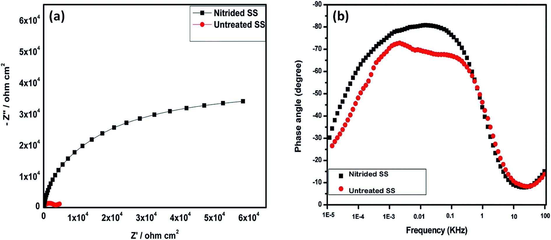
3.7 Electrochemical impedance spectroscopic (EIS) studies
EIS studies carried out for the untreated and nitrided 316L SS to evaluate the corrosion resistance and are shown in Fig. 6(a and b) in the form of Nyquist and Bode phase angle plots. In Nyquist plot, the diameter of the low frequency semi circle of nitrided SS was found to be high compared to that of untreated 316L SS. This is due to less number of defects as well as surface homogeneity, which could be due to the existence of the stable passive film that resists the inward penetration of corrosive ions such as F− and SO42−.25 The nitrided SS exhibited higher charge transfer resistance (Rct) value, indicating higher corrosion resistance (low corrosion rate) in PEMFC operating environment.24
 |
| | Fig. 6 (a) Nyquist and (b) Bode phase angle plots of untreated and nitrided SS in PEMFC environment. | |
In phase angle plot (Fig. 6(b), the high frequency plots of untreated and nitrided SS merge together because of the local surface defects occurring on the surface but in low frequency, phase angle was relatively high for nitrided SS compared to untreated one. This is due to the faster moving corrosive ions and water from the electrolyte solution to the untreated SS. Hence, rapid dissolution occurs on metal surface leading to poor corrosion resistance. The capacitance (Q) was replaced with CPE, and written in admittance form26 as given below,
where,
YO is an adjustable parameter used in non-linear least square fitting analysis and
n is obtained from the phase angle plot and that lies in the range of 0.83 for untreated and 0.89 for nitrided SS respectively. The
n values of both the system are near to ideal capacitive behaviour. The analysis of the EIS parameters by mathematical modeling with an equivalent circuits and are shown in
Fig. 7(a) and (b). The higher polarization resistance of the nitrided SS was attributed to the existence of two time constants as shown by the equivalent circuit (b). The constituent elements of both the circuits were,
RS denotes the solution resistance between the reference and working electrodes, CPE represents the constant phase element and
Rct is the charge transfer resistance of the metal/coating interface. Fig. S2 in ESI
† compares the values of the parameters in the EEC model of the untreated and nitrided SS surfaces. It can be seen that increase in
Rct value of nitrided SS indicates the ability to protect the metal from corrosive ions and water.
Qpore and
Rpore is the film capacitance and resistance respectively.
Qdl is the double layer capacitance that provides the details about the charge separation and polarity of the substrate/electrolyte interface. We can see that the Fig. S2 in ESI,
† the lower capacitance value of nitrided SS showed the higher corrosion resistance in PEMFC environment.
 |
| | Fig. 7 Equivalent circuits for untreated (a) and nitrided SS (b) in PEMFC environment. | |
4 Conclusions
Electrochemically generated nitride layer was deposited on 316L SS using potentiostatic technique. The XPS studies revealed that two types of nitrides namely N–NH3 and CrN, Cr2N mixed nitrides were detected over the surface. High contact angle and low surface resistance values of nitrided SS favors PEMFC operating conditions. Potentiodynamic and potentiostatic polarization test results showed that the nitrided SS has decreased current density indicating enhanced corrosion resistance. EIS studies confirmed the high charge transfer resistance and hence demonstrated low corrosion rate for nitrided SS. From these observations, it can be concluded that the nitrided 316L SS is a promising Bp material in PEMFC environment.
Acknowledgements
One of the authors S. Pugal Mani is thankful to the UGC, New Delhi for providing UGC-BSR fellowship. The instrument facilities provided by DST-FIST and UGC-DRS are gratefully acknowledged.
References
- Q. Hu, D. Zhang, H. Fu and k. Huang, Int. J. Hydrogen Energy, 2014, 39, 13770 CrossRef CAS PubMed.
- Z. K. Tu, H. N. Zhang, Z. P. Luo, J. Liu, Z. M. Wan and M. Pan, J. Power Sources, 2013, 222, 277 CrossRef CAS PubMed.
- C. K. Jin, M. G. Jeong and C. G. Kang, Int. J. Hydrogen Energy, 2014, 39, 21480 CrossRef CAS PubMed.
- X. Hairong, W. Tao, G. Hu, F. Xioati, Z. Zetao, P. Zuchen and H. Jianping, RSC Adv., 2014, 4, 57724 RSC.
- S. Ladre, O. E. Kongstein, A. Oedegarrd, F. Seeland and H. Karoliussen, Int. J. Hydrogen Energy, 2012, 37, 18537 CrossRef PubMed.
- W. P. Tong, N. R. Tao, Z. B. Wang and J. Lu, Science, 2003, 299, 686 CrossRef CAS PubMed.
- H. Wang, G. Teeter and J. A. Turner, J. Fuel Cell Sci. Technol., 2010, 7, 021019 CrossRef.
- H. Wang, M. P. Brady, K. L. More, H. M. Meyar and J. A. Turner, J. Power Sources, 2004, 138, 79 CrossRef CAS PubMed.
- R. Tian, J. Sun and L. Wang, Int. J. Hydrogen Energy, 2006, 31, 1874 CrossRef CAS PubMed.
- R. Tian, J. Sun and L. Wang, J. Power Sources, 2007, 163, 719 CrossRef CAS PubMed.
- H. Wang, G. Teeter and J. A. Turner, J. Fuel Cell Sci. Technol., 2010, 7, 021018 CrossRef.
- R. D. Willenbruch, C. R. Clayton, M. Oversluzien, D. Kim and Y. Lu, Corros. Sci., 1990, 31, 179 CrossRef CAS.
- C. R. Clayton, G. P. Halada and J. R. Kearns, Mater. Sci. Eng., A, 1995, 198, 135 CrossRef.
- H. Wang, G. Teeter and J. A. Turner, J. Mater. Chem., 2011, 21, 2064 RSC.
- H. Wang and J. A. Turner, J. Fuel Cell Sci. Technol., 2013, 10, 1002 Search PubMed.
- S. P. Mani, A. Srinivasan and N. Rajendran, Int. J. Hydrogen Energy, 2015, 40, 3359 CrossRef PubMed.
- G. T. Burstein, I. M. Hucthings and K. Sasaki, Nature, 2000, 407, 885 CrossRef CAS PubMed.
- D. Kim, C. R. Clayton and M. Oversluizen, Mater. Sci. Eng., A, 1994, 186, 163 CrossRef CAS.
- C. R. Clayton, G. P. Halada and J. R. Kearns, Mater. Sci. Eng., A, 1995, 198, 135 CrossRef.
- Y. H. Yun, J Ceram Process Res., 2007, 8, 440 Search PubMed.
- Y. Fu, G. Lin, M. Hou, B. Wu, H. Li, L. Hao, Z. Shao and B. Yi, Int. J. Hydrogen Energy, 2009, 34, 453 CrossRef CAS PubMed.
- L. Wang, D. Northwood, X. Nie, J. Housden, E. Spain and A. Leyland, J. Power Sources, 2010, 191, 3814 CrossRef PubMed.
- N. D. Nam, S. J. Deok, J. G. Kim and D. H. Yoon, Thin Solid Films, 2011, 519, 6787 CrossRef CAS PubMed.
- N. D. Nam, M. Vaka and H. T. Nguyen, J. Power Sources, 2014, 268, 240 CrossRef CAS PubMed.
- N. D. Nam, J. G. Kim and W. S. Hwang, Thin Solid Films, 2010, 518, 6598 CrossRef CAS PubMed.
- V. K. W. Grips, V. E. Selvi, H. C. Barshilia and K. S. Rajam, Electrochim. Acta, 2006, 51, 346 CrossRef PubMed.
Footnote |
| † Electronic supplementary information (ESI) available. See DOI: 10.1039/c5ra05412e |
|
| This journal is © The Royal Society of Chemistry 2015 |
Click here to see how this site uses Cookies. View our privacy policy here.