A 3D porous interconnected NaVPO4F/C network: preparation and performance for Na-ion batteries

Maowen Xu *ab, Chuan-Jun Chengab, Qiang-Qiang Sunab, Shu-Juan Baoab, Yu-Bin Niuab, Hong Heab, Yutao Lic and Jie Songc
aInstitute for Clean Energy & Advanced Materials, Faculty of Materials and Energy, Southwest University, Chongqing 400715, P.R. China. E-mail: xumaowen@swu.edu.cn
bChongqing Key Laboratory for Advanced Materials and Technologies of Clean Energies, Chongqing 400715, P.R. China
cTexas Materials Institute, University of Texas at Austin, Texas 78712, USA

Received 24th March 2015 , Accepted 27th April 2015

First published on 27th April 2015


Abstract

A uniform carbon embedded nano-scale NaVPO4F precursor of 3–5 nm is fabricated by a hydrothermal method and using vitamin C as the carbon source and reducing agent, followed by a sintering process, the carbon embedded NaVPO4F precursors transformed into a kind of 3D porous interconnected NaVPO4F/C network. As a Na-ion battery cathode material, the NaVPO4F/C network obtained at 750 °C achieves a high discharge capacity of 121 mA h g−1 and the sample obtained at 800 °C shows a slightly lower discharge capacity of 101 mA h g−1, but better rate capability and long cycle life. These results indicate that the 3D porous NaVPO4F/C network not only improves the electronic conductivity of the active material, but also prevents the aggregation of particles, and its open porous structure allows electrolyte penetration, and reduces the diffusion path of the sodium ions, hence maximizing utilization of the electrochemically active NaVPO4F particles.

Introduction

Energy storage and conversion technology is widely used in portable electronic products, and this technology is gaining worldwide attention for its transportation applications, along with other large-scale renewable energy storage equipment.1–3 Among the candidates, despite the popularity of Li-ion batteries in energy storage applications, their relatively high cost and the geographic constraints associated with lithium resources have motivated a search for cheaper and more sustainable alternatives.4–6 In comparison, sodium resources are inexhaustible and unlimited around the world. After lithium, the electrochemical equivalent and standard potential of sodium are the most advantageous for aprotic battery applications; therefore, sodium-ion batteries are receiving widespread attention.7–9 However, only a limited number of successful candidates are found for sodium insertion as cathode materials compared to those for lithium ion batteries.

Recently, some layered compounds and F-containing V-based polyanion compounds have been investigated as possible cathode materials for Na-ion batteries, such as NaxMO2 (M = V, Co, Mn, Fe),10–13 NaVPO4F,14 Na3V2O2(PO4)2F,15 Na3V2(PO4)2F3,16 and Li1.1Na0.4VPO4.8F0.7.17 Among these candidates, NaVPO4F has recently attracted extensive attention because of its high theoretical specific capacity of 143 mA h g−1 and its open framework structure.18 NaVPO4F with a tetragonal structure was first proposed by J. Barker et al.,18 and various methods were introduced to prepare NaVPO4F, including two-step solid state reaction, hydrothermal approach and sol–gel synthesis.18–20 However, the capacity of the reported NaVPO4F materials is far below its theoretical specific capacity and they show bad cycling performance.

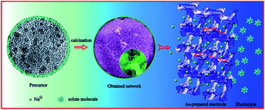
Carbon coating is an effective approach to increase the electronic conductivity and electrochemical performance of the cathode materials.21–23 There are many studies on enhancing the overall performance of cathode materials by carbon coating and different synthesis methods. Designing a porous network is another effective strategy for improving the performance of the electrode owing to favorable electrolyte absorption and significant reduction of sodium-ion diffusion paths.24 Herein, we report a novel approach to synthesize NaVPO4F/C network which consists of nanoparticles and microparticles with open interconnected 3D porous microstructure. As shown in Fig. 1, the NaVPO4F/C precursor obtained by dropping absolute alcohol to NaVPO4F precursor solution and following by hydrothermal reaction consisted of uniformed nanoparticles and completely coated with carbon. After calcination, the embedded nanosize NaVPO4F grew up and aggregated together and outer carbon layer played an important role in forming the 3D porous interconnected NaVPO4F network. This simple approach could be extended to other battery materials to obtain improved electrochemical performance.


image file: c5ra05161d-f1.tif
Fig. 1 Schematic of design and fabrication of three-dimensional NaVPO4F/C network and electron and ion transfer pathway inside NaVPO4F/C network.

Experimental

Material preparation

2 mmol NH4VO3 and 2 mmol NaF were dissolved into 10 mL deionized water under stirring at 80 °C in a 100 mL beaker. 2 mmol NH4H2PO4 and 3 mmol vitamin C were dissolved into 10 mL deionized water, and then slowly dropped into the above solution under continuous stirring. Subsequently a blue solution was obtained. Then 50 mL absolute alcohol was added to this mixed solution and kept continuous stirring for 0.5 h. The as obtained blue suspension was transferred into two separate 50 mL Teflon autoclaves. The autoclaves were sealed, kept at 180 °C for 24 h, and then cooled to room temperature naturally. The as-synthesized precipitate was collected by centrifugation and frozen dried to get a black brown precursor. Finally, the prepared precursors were calcined at 750 °C and 800 °C for 6 h under argon, respectively. The samples sintered at 750 °C and 800 °C were denoted as NaVPO4F-750 and NaVPO4F-800, respectively. Similarly, in order to optimize the reaction conditions, the samples were prepared in different times and under different temperatures.

Material characterization

The crystal structure of the products was characterized by X-ray diffraction (XRD-7000). Morphology and microstructure of the synthesized materials was investigated by field emission scanning electron microscopy (JSM-6700F, Japan) and transmission electron microscopy (JEM-2010, Japan). The carbon content was tested by CHNOS elemental analysis (vario EL CUBE, Germany).

Electrode fabrication and electrochemical tests

To evaluate the electrochemical performance of the as-prepared sample, CR2032-type coin cells were fabricated in an argon-filled glove box. This coin cell was composed of sodium anode, cathode, Celgard polypropylene separator, and 1 M NaPF6 solution in a mixture of ethylene carbonate (EC) and diethyl carbonate (DEC) (EC/DEC, 1[thin space (1/6-em)]:[thin space (1/6-em)]1 v/v) as the electrolyte. The cathode was prepared by spreading the slurry of the active material (80 wt%), carbon black (10 wt%) and the poly(vinylidene fluoride) (10 wt%) binder dissolved in N-methyl pyrrolidine on Al foil. The working electrolytes were dried in vacuum at 120 °C for overnight. The loading of the active material (NaVPO4F/C) was about 2–3 mg cm−2. The assembled cells were rested for 24 h prior to further testing in order to ensure full absorption of the electrolyte into the working electrode. Charge–discharge tests were performed at room temperature with an Arbin.

Results and discussion

The XRD patterns of the as-synthesized samples display in Fig. 2. In order to optimize the reaction conditions, some experiments were done in different react times and temperatures (see Fig. S1 and S2). The pattern of Fig. 2a suggests the precursor obtained in hydrothermal reaction at 180 °C for 24 h has a tetragonal symmetry structure (space group I4/mmm). VO4F2 octahedra and PO4 tetrahedra stack an extended three-dimensional framework. The position of its diffraction peaks agrees with the previous work published by Barker et al.18,19 However, the intensity of its diffraction peaks embodies the characteristics of amorphous materials. After sintering at 750 °C and 800 °C, the XRD results (Fig. 2c and d) are in good agreement with that reported by Zhou et al.,14,20,25 suggesting the phase of monoclinic crystal (space group C2/c), two PO4 tetrahedra share two corner-oxygen atoms with two different VO4F2 octahedra. While the product formed at 700 °C is a mixed phase of tetragonal structure and monoclinic crystal (Fig. 2b).
image file: c5ra05161d-f2.tif
Fig. 2 XRD patterns of NaVPO4F/C composites (a) hydrothermal method at 180 °C for 24 h, (b) precursor after calcined at 700 °C for 6 h, (c) precursor after calcined at 750 °C for 6 h, (d) precursor after calcined at 800 °C for 6 h.

NaVPO4F have been conventionally synthesized by hydrothermal method or the two-step solid state. The reaction intermediate phase is VPO4, prefabricated by the high temperature carbon-thermal reduction reaction.18 In this work, we first prepare uniformly carbon embedded nano-scaled NaVPO4F precursors by a feasible and environmentally friendly hydrothermal method utilizing vitamin C as both the carbon sources and the reducing agent. And then further to sinter the obtained precursors at high temperature to form 3D porous interconnected NaVPO4F/C network. The unique architecture of the NaVPO4F/C precursor used in our work is displayed in Fig. 3. It is clear that the precursor is very uniform nanoparticles, the NaVPO4F nanoparticles with diameters of 3–5 nm are embedded in the carbon matrix.


image file: c5ra05161d-f3.tif
Fig. 3 SEM (a) and TEM (b and c) of carbon embedded NaVPO4F obtained at hydrothermal process.

The product sintered at 750 °C displays 3D interconnected network structure composed of uniform particles (Fig. 4a). These grown particles are connected together and disordered carbon distribute between these big particles (Fig. 4b and c). NaVPO4F sintered at 750 °C, which is coated by fine amorphous carbon coating layers, displayed clear crystal planes (Fig. 4d). The thickness of the carbon layer is about ∼5 nm (Fig. 4d). The carbon embedded NaVPO4F precursor can prevent the aggregation of NaVPO4F particles, and help to form porous interconnected network structure. For the NaVPO4F samples fired at 800 °C, the particle size is in the range of 1–3 μm; these microparticles interweave together forming an open porous structure. (Fig. 4e and f). These coating carbon on NaVPO4F nanoparticles create a carbon network and improve the electronic conductivity, the width of bridge-like carbon is about 10–50 nm (Fig. 4g and h). Such a well-organized 3D interconnected network structure facilitates the electrolyte penetration into the NaVPO4F particles and provides more interface area between the electrolyte and the electrode material. The carbon content in NaVPO4F/C precursors, NaVPO4F/C sintered at 750 °C and 800 °C are estimated by elemental analysis. The results showed that the carbon content is about 9.6 wt%, 2.9 wt% and 1.4 wt% of the samples by hydrothermal method, sintered at 750 °C and 800 °C, separately. In additional, as shown in the Fig. S3–S5, the energy dispersive spectrometer (EDS) mapping shows no impurity elements. All five elements –Na, V, P, O and F are present uniformly throughout the bulk of the sample.


image file: c5ra05161d-f4.tif
Fig. 4 SEM and TEM of NaVPO4F/C composites obtained at different temperatures. (a–d) 750 °C and (e–h) 800 °C.

In order to examine the potential application of NaVPO4F/C network in sodium ion batteries, the electrochemical properties of NaVPO4F/C composite were tested in the coin half-cells at room temperature in the voltage range of 2.5–4.2 V. Fig. 5a shows the cyclic voltammograms of the obtained composites at a scan rate of 0.1 mV s−1. It is seen that the NaVPO4F precursor obtained during hydrothermal process shows unobvious peaks and the redox couple is at around 3.55 V/3.65 V. And one wide redox couple (3.1 V/3.5 V) can be observed for the NaVPO4F sintered at 750 °C. When the sintering temperature increases to 800 °C, two redox couples at 3.15 V/3.45 V and 3.6 V/3.7 V can be identified. Fig. 5b illustrates the typical first cycle profiles of charge–discharge curves at 0.1 C (corresponds to 14.3 mA g−1). The charge and discharge plateaus of NaVPO4F materials agree with the CV results. Because of different phases, the redox potential of NaVPO4F precursor is about 0.5 V higher than that of the samples obtained by sintered at high temperature. The specific capacity of NaVPO4F/C composites (hydrothermal, 750 °C and 800 °C) are 50 mA h g−1, 121 mA h g−1 and 101 mA h g−1, respectively. Due to the looser surface structure and higher carbon content, the NaVPO4F/C sintered at 750 °C exhibits a better specific capacity than the NaVPO4F/C sintered at 800 °C. The rate performances of NaVPO4F/C composite (hydrothermal, 750 °C and 800 °C) at various rates from 0.1 C to 1 C are illustrated in Fig. 5c. The as-synthesized NaVPO4F-750 demonstrates a good rate capability at rate 0.1 C, 0.2 C and 0.5 C (i.e., the tenth capacities of NaVPO4F-750 and NaVPO4F-800 are 115 and 97 mA h g−1 at 0.1 C, the twentieth capacities of NaVPO4F-750 and NaVPO4F-800 are 107 and 90 mA h g−1 at 0.2 C, the thirtieth capacities of NaVPO4F-750 and NaVPO4F-800 are 91 and 83 mA h g−1 at 0.5 C), which is far higher than that of the NaVPO4F/C (97.8 mA h g−1 at 0.1 C and 99.1 mA h g−1 at 0.1 C) fabricated by Y. Lu et al.14 and Y.-L. Ruan et al.26 It is interesting to find that the capacities of the as-synthesized NaVPO4F-750 and NaVPO4F-800 are basically equal (about 78 mA h g−1) at 1 C. Fig. 5d further compared the cycle stability of these samples, and the discharge capacity of hydrothermal NaVPO4F precursor decreases from 46 mA h g−1 to only 14 mA h g−1 after 65 cycles, while the NaVPO4F-750 and NaVPO4F-800 show good capacity retention, their discharge capacities reduce from 121 to 92 mA h g−1 and from 101 to 83 mA h g−1 after 65 cycles.


image file: c5ra05161d-f5.tif
Fig. 5 The electrochemical properties of NaVPO4F precursor and NaVPO4F sintered at 750 °C and 800 °C: (a) cyclic voltammograms at a scan rate of 0.1 mV s−1; (b) the typical first cycle profiles of charge–discharge curves at 0.1 C; (c) performance at various rates from 0.1 C to 1 C; (d) cycle performances at 0.1 C.

Conclusion

In this study, a kind of 3D porous interconnected NaVPO4F/C network was prepared by using carbon embedded nano-scaled NaVPO4F as precursor. The carbon embedded NaVPO4F precursor can prevent the aggregation of NaVPO4F particles, and help to form porous interconnected network structure. The unique 3D network structure provides interconnected open pores and effectively carbon coating, which allows electrolyte penetration, improves the electronic conductivity and reduces the diffusion path of the sodium ions. The results indicate that NaVPO4F/C network delivered a high discharge capacity and a good long-term cycling life. This novel method could be extended to obtain various porous materials for use in energy storage and conversion, as well as catalysis.

Acknowledgements

This work is financially supported by Chongqing Key Laboratory for Advanced Materials and Technologies of Clean Energies under cstc2011pt-sy90001, Start-up grant under SWU111071 from Southwest University and Chongqing Science and Technology Commission under cstc2012gjhz90002. The work is also supported by grants from the National Natural Science Foundation of China (no. 21063014, 21163021), Fundamental Research Funds for the Central Universities (SWU113079, XDJK2014C051) and Research Funds for a postdoctor of Chongqing (xm2014097)

Notes and references

  1. M. S. Whittingham, Chem. Rev., 2014, 114, 11414–11443 CrossRef CAS PubMed.
  2. J. Xie, C. X. Guo and C. Li, Energy Environ. Sci., 2014, 7, 2559–2579 CAS.
  3. M. D. Slater, D. Kim, E. Lee and C. S. Johnson, Adv. Funct. Mater., 2013, 23, 947–958 CrossRef CAS PubMed.
  4. S. W. Kim, D. H. Seo, X. Ma, G. Ceder and K. Kang, Adv. Energy Mater., 2012, 2, 710–721 CrossRef CAS PubMed.
  5. M. Xu, L. Wang, X. Zhao, J. Song, H. Xie, Y. Lu and J. B. Goodenough, Phys. Chem. Chem. Phys., 2013, 15, 13032–13037 RSC.
  6. J. Liu, K. Tang, K. Song, P. A. van Aken, Y. Yu and J. Maier, Nanoscale, 2014, 6, 5081–5086 RSC.
  7. H. Pan, Y.-S. Hu and L. Chen, Energy Environ. Sci., 2013, 6, 2338–2360 CAS.
  8. V. Palomares, M. Casas-Cabanas, E. Castillo-Martínez, M. H. Han and T. Rojo, Energy Environ. Sci., 2013, 6, 2312–2337 CAS.
  9. W. Song, X. Ji, Z. Wu, Y. Yang, Z. Zhou, F. Li, Q. Chen and C. E. Banks, J. Power Sources, 2014, 256, 258–263 CrossRef CAS PubMed.
  10. M. Guignard, C. Didier, J. Darriet, P. Bordet, E. Elkaïm and C. Delmas, Nat. Mater., 2013, 12, 74–80 CrossRef CAS PubMed.
  11. R. Berthelot, D. Carlier and C. Delmas, Nat. Mater., 2011, 10, 74–80 CrossRef CAS PubMed.
  12. M. M. Doeff, M. Y. Peng, Y. Ma and L. De Jonghe, J. Electrochem. Soc., 1994, 141, L145–L147 CrossRef CAS PubMed.
  13. N. Yabuuchi, H. Yoshida and S. Komaba, Electrochemistry, 2012, 80, 716–719 CrossRef CAS PubMed.
  14. Y. Lu, S. Zhang, Y. Li, L. Xue, G. Xu and X. Zhang, J. Power Sources, 2014, 247, 770–777 CrossRef CAS PubMed.
  15. M. Xu, P. Xiao, S. Stauffer, J. Song, G. Henkelman and J. B. Goodenough, Chem. Mater., 2014, 26, 3089–3097 CrossRef CAS.
  16. Z. Liu, Y.-Y. Hu, M. T. Dunstan, H. Huo, X. Hao, H. Zou, G. Zhong, Y. Yang and C. P. Grey, Chem. Mater., 2014, 26, 2513–2521 CrossRef CAS.
  17. Y.-U. Park, D.-H. Seo, B. Kim, K.-P. Hong, H. Kim, S. Lee, R. A. Shakoor, K. Miyasaka, J.-M. Tarascon and K. Kang, Sci. Rep., 2012, 2 Search PubMed.
  18. J. Barker, M. Saidi and J. Swoyer, Electrochem. Solid-State Lett., 2003, 6, A1–A4 CrossRef CAS PubMed.
  19. J. Barker, M. Saidi and J. Swoyer, J. Electrochem. Soc., 2004, 151, A1670–A1677 CrossRef CAS PubMed.
  20. J. Zhao, J. He, X. Ding, J. Zhou, Y. O. Ma, S. Wu and R. Huang, J. Power Sources, 2010, 195, 6854–6859 CrossRef CAS PubMed.
  21. Y. Luo, X. Xu, Y. Zhang, Y. Pi, Y. Zhao, X. Tian, Q. An, Q. Wei and L. Mai, Adv. Energy Mater., 2014, 4 CAS.
  22. Z. Yang, J. Xia, L. Zhi, W. Zhang and B. Pei, Ionics, 2014, 20, 169–174 CrossRef CAS PubMed.
  23. J. Wang, Z. Wang, X. Li, H. Guo, W. Xiao, S. Huang and Z. He, J. Solid State Chem., 2013, 17, 1–8 CAS.
  24. L. Dimesso, C. Förster, W. Jaegermann, J. Khanderi, H. Tempel, A. Popp, J. Engstler, J. Schneider, A. Sarapulova and D. Mikhailova, Chem. Soc. Rev., 2012, 41, 5068–5080 RSC.
  25. H. Zhuo, X. Wang, A. Tang, Z. Liu, S. Gamboa and P. Sebastian, J. Power Sources, 2006, 160, 698–703 CrossRef CAS PubMed.
  26. Y.-L. Ruan, K. Wang, S.-D. Song, X. Han and B.-W. Cheng, Electrochim. Acta, 2015, 160, 330–336 CrossRef CAS PubMed.

Footnotes

Electronic supplementary information (ESI) available. See DOI: 10.1039/c5ra05161d
Maowen Xu and Chuan-Jun Cheng contributed equally to this work.

This journal is © The Royal Society of Chemistry 2015
Click here to see how this site uses Cookies. View our privacy policy here.