
Natural-gel derived, N-doped, ordered and interconnected 1D nanocarbon threads as efficient supercapacitor electrode materials†
Malik Wahid*ab,
Golu Parteab,
Rohan Fernandesc,
Dushyant Kotharic and
Satishchandra Ogale*ab
aCentre of Excellence in Solar Energy, Physical and Materials Chemistry Division, National Chemical Laboratory (CSIR-NCL), Pune 411 008, India. E-mail: sb.ogale@ncl.res.in; malikwahid15@gmail.com; Fax: +91 20 2590 2636
bAcademy of Scientific and Innovative Research, Anusandhan Bhawan, 2 Rafi Marg, New Delhi 110001, India
cDepartment of Physics and National Centre for Nanosciences & Nanotechnology, University of Mumbai, Vidyanagri, Santacruz (E), Mumbai 400098, India
First published on 3rd June 2015
Abstract
A natural hydrogel has been successfully templated into a nitrogen doped interconnected 1D nanostructure by a hard templating method using an SBA-15 template. With urea as the nitrogen doping agent a high nitrogen percentage of 7.0 at% was achieved. Urea was seen to play a role in increasing the order and compactness of the final carbon product. By snipping the carbon into nano 1D threads a fairly high surface area up to 837 m2 g−1 was achieved with a high density of mesopores characterized by a pore size of 4–5 nm and a pore volume of 0.87–0.89 cm3 g−1. The mesoporous architecture was channel type with an average width of ∼4 nm. With these characteristics the material represents an architecture that is adequate for high power supercapacitor electrode applications. Indeed, it was seen to deliver a capacity of 285 F g−1 at a current density of 1 A g−1 with only a small percentage loss in this initial capacitance value at a higher current density of 10 A g−1 (210 F g−1). These values suggest a high capacity retention of 74% up to 10 A g−1 and 62% capacitance retention (176 F g−1) at an extremely high current density of 40 A g−1. The cycling stability of the material is also commendable as 96% capacity retention is recorded after 2000 charging–discharging cycles implemented at a high current density of 10 A g−1.
1. Introduction
The quest for high performance energy storage materials has put porous carbons at the forefront for various related applications, especially in the fields of great current significance namely renewable energy and mobility.1,2 Interestingly, the supercapacitor domain is still dominated by carbon materials almost exclusively despite some promising transition metal oxide options.3,4 Indeed, the technology focus on carbon materials is due to their high surface area for ion adsorption and desorption, appropriately and easily controllable pore size distribution for ion transport, need of less intricate device design, and above all the abundance of precursors and the inexpensive nature of the synthetic processes.5–9 However, these materials lack in their electrical conductivity and thereby in the ability to connect all the energy storage units to the current collectors. Additionally, lack of the desirable degree of conductivity offers resistive paths to the capacitive energy storage.10 Inclusion of heteroatoms (N, S, B) in the semi-graphitic carbon framework is helpful in increasing the conductivity by their participation in the delocalization of electron lone pairs through unsaturated graphitic mini lattices. Among the various heteroatoms, nitrogen has been the most efficient dopant as it is similar in size to the host carbon atom.11–20 Importantly, such heteroatom doping enables better conductivity without compromising the surface area and pore architecture.The effective accessible surface area of carbon materials for charge storage applications can be enhanced by enforcing porosity therein. The most commonly employed strategy for generating porosity is the famous activation procedure by employing either chemical or physical activating agents which work by digging holes in the carbon matrix. Two types of activation procedures are employed: (1) ex situ activation, that is effected by carrying out pyrolysis in the presence of activation agents19,21–28 (KOH, NaOH, ZnCl2, CO2, and steam etc.), and (2) in situ activation, which is effected by direct pyrolysis of salt of a suitable organic carbon precursor.12,29–34
Besides activation the other interesting strategy employed for the generation of high surface area carbons has been the hard templating method. This method involves infiltration of a carbon precursor inside the nano dimensional physically separated spaces followed by high temperature inert atmosphere pyrolysis. Physical barriers prevent the union of carbon–carbon grains and thus enable one to snip the carbon framework into nano-dimensional morphologies. Assembly of such nano-carbon structures ensures enough spaces which give rise to porosity and hence to high surface area.35–40 Mesoporous silica templates like (SBA-15, KIT) have proved efficient in this respect, being chemically inert and stable up to very high temperatures.41–46
Template based synthesis of carbon materials started with the infiltration of sucrose inside the MCM-48 template in 1999.40 Thereafter glucose, xylose, furfuryl alcohol, and phenol resins have been reported to have been infiltrated and mesoporous carbon derived by this process. However, complete reverse replication of silica template by the carbon synthesized inside the porous matrix was achieved for the first time by infiltration of sucrose in SBA-15.40 Sang Hoon Joo et al. infiltrated furfuryl alcohol inside SBA-15 and successfully carried out the polymerization inside the pores. Carbon material thus obtained by pyrolysis was a complete reverse replica of the silica template.36 Infiltration of readymade resorcinol gel inside the mesoporous channels and the energy storage application of the corresponding carbon material has been reported very recently.15 Gel infiltration in the channels is a slow process and needs 2–3 infiltration cycles. However, it offers the advantage of unbreakable channels which terminate into one dimensional carbon structures upon pyrolysis. One dimensionality of the final carbon product can be attributed to the poor fluidity of the gel which resists the diffusion through the complementary pores in the mesoporous channels and makes them isolated nano reactors.
Herein we report the template based synthesis of super-capacitive carbon by infiltration of a natural hydro gel, pectin, in SBA-15 followed by pyrolysis in inert atmosphere. This is for the first time that natural gel has been directly infiltrated and pyrolysed inside a synthetic template for the synthesis of carbon for supercapacitor applications. Choice of pectin as precursor for the mentioned template based synthesis was made for it being easily available, cheap, naturally abundant and its efficient convertibility to carbon upon pyrolysis.47 Pectin being a hydrogel, forms long unbreakable columns inside the silica channels with less sideways diffusion, fulfilling all the necessary requirements for the transformation into one dimensional carbon threads. Added superiority of pectin over other gels (like resorcinol, PVA, PVP, etc.) as a precursor for the carbon synthesis lies in the presence of enough –OH groups available for hydrogen bonding with water and with the template walls.36,48 Close binding with solvent through such physicochemical interaction is important to achieve deep penetration. Hydrogen bonding with the –OH groups of template channel walls amplifies the advantage as it leads to close packing inside the channel.
Pectin is a biopolymer and a close ally of biopolymers agarose and alginate which form thick hydrogels in water. Chemically, pectin is a polymer of α-glucuronic acid linked together by 1,4 glucosidic linkages having its carboxylic group esterified. Commercial pectin has its carboxylic groups amidated (15–25%) which give some percentage of nitrogen doping (1–2 at%) into the carbons derived from it. To achieve even higher nitrogen doping urea was used as a doping agent being fairly soluble in water and having a tendency to form hydrogen bonds with the –OH groups of pectin. With the use of urea a high nitrogen percentage of 7.0 at% could be realized. Presence of urea in the infiltration mixture leads to viscosity enhancement by attachment with polymer strands of the gel. The more viscous the infiltrating solution more is the resistance it faces for sideways flow even at higher temperatures, leading to more compactness in the final carbon. Interconnected structure of 1D nano-threads possessing surface area of 837 m2 g−1 is thus achieved. The porosity is mostly mesoporous with small amount of micropores. With these specifications our material offers a great promise for high power delivery super-capacitor material.
2. Experimental section
2.1 Materials used
Pluronic 123 and tetra ethyl orthosilicate were purchased from Aldrich. Pectin and alginate were purchased from sigma chemicals, and agarose was purchased from invitrogen chemicals. Urea for the experiments was purchased from Merck chemicals.2.2 Synthesis of template
For the synthesis of SBA-15 template an already reported procedure was followed with tri block Pluronic 123 as the structure directing agent and tetra ethyl orthosilicate (TEOS) as the silica source.442.3 Synthesis and nomenclature of different pectin derived carbon samples
![[thin space (1/6-em)]](https://www.rsc.org/images/entities/char_2009.gif) :1 (i.e. addition of 2 g urea in 30 ml DI water to 50 ml of 2 g pectin gel solution) without the use of a template. P0-SBA means carbon sample prepared by pyrolysis of pectin (i.e. addition of 0 g urea in 30 ml DI water to 50 ml of 2 g pectin gel solution) inside a 0.6 g SBA-15 template. PU-SBA21 means carbon material prepared by pyrolysis of 2 g pectin +1 g urea (i.e. addition of 1 g urea in 30 ml DI water to 50 ml of 2 g pectin gel solution in the synthesis procedure) inside 0.6 g a SBA-15 template. PU-SBA11 means carbon material prepared by pyrolysis of 2 g pectin + 2 g urea (i.e. addition of 2 g urea in 30 ml DI water to 50 ml of 2 g pectin gel solution in the synthesis procedure) inside a SBA-15 template.
:1 (i.e. addition of 2 g urea in 30 ml DI water to 50 ml of 2 g pectin gel solution) without the use of a template. P0-SBA means carbon sample prepared by pyrolysis of pectin (i.e. addition of 0 g urea in 30 ml DI water to 50 ml of 2 g pectin gel solution) inside a 0.6 g SBA-15 template. PU-SBA21 means carbon material prepared by pyrolysis of 2 g pectin +1 g urea (i.e. addition of 1 g urea in 30 ml DI water to 50 ml of 2 g pectin gel solution in the synthesis procedure) inside 0.6 g a SBA-15 template. PU-SBA11 means carbon material prepared by pyrolysis of 2 g pectin + 2 g urea (i.e. addition of 2 g urea in 30 ml DI water to 50 ml of 2 g pectin gel solution in the synthesis procedure) inside a SBA-15 template.2.4 Characterization and measurements
The different carbon samples synthesized from pectin were examined by X-ray powder diffraction using a Philips X'Pert PRO diffractometer with nickel-filtered CuKα radiation. Raman spectroscopy was performed using LabRAM HR800 from JY Horiba. High-resolution transmission electron microscopy was performed using IFEI, Tecnai F30, FEG system with 300 kV. FESEM was performed with the help of Nova Nano SEM 450. The surface area values for all the samples were determined by the Brunauer–Emmett–Teller (BET) adsorption method (Quadrasorb automatic volumetric instrument). XPS was acquired using a PHI 5000 Versa Probe II equipped with a mono-chromatic Al Ka (1486.6 eV), a X-ray source and a hemispherical analyzer. Appropriate electrical charge compensation was employed. Cyclic voltammetry measurements were performed using Auto Lab (model PGSTAT 30, eco-chemie).2.5 Electrode preparation for electrochemical measurements
The electrodes were prepared by coating a slurry of 80 wt% carbon material, 15 wt% carbon-black and 5 wt% polyvinylidene difluoride (PVDF) in N-methylpyrrolidine on 1 cm2 area of carbon fibre paper strips (1 cm × 3.5 cm) followed by drying at 90 °C for 24 h. Three electrode measurements were performed with carbon coated on a carbon fibre paper as working electrode, platinum strip as counter electrode and calomel as reference electrode in 1 M H2SO4. Two electrode measurements were performed on a cell with the material coated on two carbon fibre paper electrodes in 1 M H2SO4.2.6 Calculations
X-ray photoelectron spectroscopy (XPS) based atomic percentage calculations were carried out by subtracting the adsorbed oxygen peak from the total area. Atomic sensitivity factors of 0.296 for carbon, 0.477 for nitrogen and 0.711 for oxygen were taken into consideration for the calculation of relative atomic percentages.The gravimetric capacitance was calculated from charge–discharge plots using the following equations:
| Cg = I × t/(m × ΔV) and Cg = 2 × I × t/(m × ΔV) |
The energy density and power density were calculated on the basis of the following equations for two electrode cell:
3. Results and discussions
The synthesis of one dimensional carbon structures was achieved inside the special template SBA-15 with mesoporous long channels. Fig. 1 shows the TEM micrographs of the template material at different magnifications. The continuous channel type structures are distinctly visible with no observable breaks throughout the particle. SEM images of the particles are displayed in Fig. S1 (ESI†), the particle size of 800 nm to 1 μm is observed. Thus, such a material can be utilized as a hard template for the synthesis of one dimensional 100–150 nm long carbon structures. As the synthesis involves infiltration of sufficiently fluidic gel preparations into the channels of SBA-15 and pyrolysis therein, long one dimensional threads of carbon were expected upon dissolution of the template. This is what is clearly revealed by the electron microscopy images. Fig. 2 shows the electron microscopy images (at different magnifications) for 1:1 weight ratio sample, PU-SBA11.
 | ||
| Fig. 1 (a) to (c) show the TEM images of SBA-15 template at different resolutions. Mesoporous channels are clearly visible with diameter of ∼4–6 nm. | ||
 | ||
| Fig. 2 Reveals the surface morphological characteristics and fine structuring of PU-SBA11 at different resolutions. In SEM micrographs (a–c) porous diffuse interconnected structures composed of uniformly arranged bundles of fine threads. The diameters of these carbon threads are about 4–6 nm as revealed by TEM micrographs (d–f). | ||
Fig. 2a to c show the FE-SEM images of PU-SBA11. The uniformly distributed carbon nano-aggregations can be seen in Fig. 2a. The magnified images in Fig. 2b and c show that these carbon aggregates are composed of ordered nano-carbon threads bundled together. The images clearly reveal that the morphology is complementary to the silica template used (please see Fig. 1 and S1†). The TEM images in Fig. 2d to f further establish the complementary relationship between the silica template used and the carbon structures obtained. The continuous mesoporous channels are the hallmark of such morphology and distinguish it from ordered mesopores that have been obtained by templating various sugars and other natural materials inside variety of silica templates.48
Fig. 3 shows the FESEM images for comparison of various pectin-derived carbon samples of different denominations synthesized by varying the weight ratios of pectin and urea. It can be seen that by templating we have been able to snip micron dimensional carbon morphology (Fig. 3a and b) into nanoscale quasi-one dimensional structures (Fig. 3e).
 | ||
| Fig. 3 Comparison of the final morphology of pectin derived carbons at similar resolutions. Figures (a) and (b) show that typical flat low surface area topography of P0-00 and PU-00 samples respectively. Figures (c) to (e) show the effect of urea on templating. Figure (c) shows the slouchy P0-SBA carbon, (d) relatively ordered but loose arrangement of carbon threads in PU-SBA21, and (e) shows ordered carbon threads compactly packed into carbon bundles. | ||
It is interesting to note that the presence of urea during pyrolysis has a marked influence on the final morphology. The compactness is observed to have increased with the increase in the urea to pectin weight ratio. This is confirmed by the morphology comparisons. The slouchy carbon morphology of P0-SBA (Fig. 3c) can be clearly distinguished from loosely arranged one dimensional carbon threads of PU-SBA21 (Fig. 3d) and well ordered compactly packed nano threads of PU-SBA11 (Fig. 3e). Additionally FE-SEM images shown in Fig. S2† display a comparison of the final morphology of carbon material prepared from pectin, PU-SBA11 with the carbon prepared from two other natural gels i.e. agarose (AgU-SBA11) and alginate (AlU-SBA11). It can be concluded that better infiltration of gel into the silica template is achieved in the case of pectin which leads to ordered and compact final carbon structure as compared to carbon from agarose and alginate. Carbon derived from pectin completely replicates the silica template which is not the case for agarose and alginate derived carbons. In order to account for the carbon morphology differences, the chemical composition and structure of three gels was surveyed. Fig. S3† shows the chemical structural formulae of the gels. The superiority of pectin over agarose gel for this particular synthetic strategy can be better appreciated by listing the total number of hydrogen bonding sites in each polymer.
A unit of pectin polymer (dimer) has four additional hydrogen bonding centres as compared to a similar unit (dimer) of agarose. The additional hydrogen bonding centres in pectin lie in the polar carboxylic groups of galacturonic acid moieties at C5 position, two of which are present in each dimer. A dimer unit of agarose in comparison to pectin is composed of galactopyranose moiety which has a free OH group at C5 position, connected to 3,6anhydro-galactopyranose which has its –OH groups at position 3 and 5 locked in an anhydrous bond. Thus in each dimeric unit pectin has four additional hydrogen bonding centres as compared to agarose. Alginate which is a polymer of α-glucuronic acid and β-mannuronic acid possesses chemical structure similar to pectin except for the differently oriented –COOH moiety in mannuronic unit. The different spatial orientation of the –COOH group reduces the number of hydrogen bonding sites by two as compared to pectin. Different levels of effective templating in the three cases which depends upon bonding with –OH groups of silica can be attributed to the number of these effective H-bonds.
To elucidate the order and arrangement of crystal planes X-ray diffraction (XRD) and Raman techniques were utilized. Fig. 4 shows the XRD plots of the different carbon samples prepared from pectin. Two broad diffraction peaks centred at around 24.6° and 43.7° can be observed in Fig. 4a, corresponding to the graphitic 002 and 100 planes of carbon, respectively. The peak at 24.6° corresponds to the graphitic inter-planner separation of 0.36 nm. The XRD peaks in the case of other carbon samples fall around the same range with minor shifts pointing to basically similar atomic arrangements and similar lattice spacings in all the pectin derived samples. Fig. 4b shows the Raman spectra of various carbons synthesized from pectin. All the samples exhibit the characteristic Raman disorder induced D-band and graphitic G-band in the range of 1329–1336 cm−1 and 1575–1585 cm−1 respectively.49,50 The Raman parameters for all the samples derived from pectin match well with each other (Table 1) which implies broadly similar local atomic arrangements and that the primary changes occur in morphology and pore structure. ID/IG ratio of 1.4 reflects better graphitic order comparable to commercial activated carbon (Norit CA1). FWHM values for P0-SBA, PU-SBA21 and PU-SBA11 samples for the graphitic G-band stretch from 0.99, through 1.04 to 1.24. The increase in broadness can be attributed to the increase in the defect density (disorder) due to nitrogen doping.
 | ||
| Fig. 4 (a) XRD plots of pectin derived carbons, and (b) Raman plots of all pectin derived carbons. | ||
| Sample | BET analysis | Raman data | XPS analysis | ||||||
|---|---|---|---|---|---|---|---|---|---|
| Surface area (m2 g−1) | Avg. pore width (nm) | Meso/micro (%) | G/D band position (cm−1) | ID/IG ratio | FWHM (G/D) (cm−1) | Carbon (%) | Nitrogen (%) | Oxygen (%) | |
| P0-00 | 4 | 2.7 | 99 | 1575/1329 | 1.4 | 114/280 | 76.9 | 2.3 | 20.8 |
| PU-00 | — | — | — | 1575/1329 | 1.4 | 114/280 | 78.5 | 3.4 | 18.1 |
| P0-SBA | 211 | 1.4 | 71 | 1582/1329 | 1.4 | 99/238 | 90.3 | 2.6 | 7.1 |
| PU-SBA21 | 618 | 1.3 | 78 | 1581/1335 | 1.4 | 103/250 | 90.9 | 3.4 | 5.7 |
| PU-SBA11 | 837 | 1.4 | 83 | 1580/1336 | 1.5 | 124/275 | 87.5 | 7.0 | 5.5 |
X-ray photo electron spectroscopy was performed to check the surface layer elemental composition of different carbon samples. Fig. S4† shows the comparison of survey spectra of all the pectin derived carbons. As can be seen from the survey spectra, all pectin carbons show a characteristic nitrogen peak at ∼400 eV besides carbon and oxygen peaks located at ∼284 eV and ∼531 eV.51–53 Presence of this nitrogen peak in non-nitrogen doped samples can be traced to some amount of nitrogen present intrinsically in pectin itself and can be ascribed to certain degree of amidation in otherwise esterified carboxylic groups.54,55 The deconvoluted carbon C1s spectra for all the pectin derived carbon forms are shown in Fig. S5.† These are also characterized by a peak at 285.7 eV assigned to nitrogen–carbon bond. The deconvoluted individual nitrogen peaks for P0-00, P0-SBA, PU-SBA21 and PU-SBA11 are shown in Fig. 5a to d. In the samples P0-00, and P0-SBA where no external doping was enforced nitrogen doping percentages of 2.3 at% and 2.6 at%, respectively, are observed. Increase in urea to pectin ratio has definitely led to increased doping of nitrogen in the carbon lattice. Nitrogen doping percentages of ∼7.0 at% was detected in PU-SBA11 and a nitrogen percentage of 3.4 at% was detected in PU-SBA21. Nitrogen percentage of 3.4 at% was also observed for PU-00. This observation shows the positive feedback effect of confined spaces in efficient doping. To complement the XPS findings EDS analysis of PU-SBA11, PU-SBA21, P0-SBA samples was performed. EDS data, Fig. S6 (ESI†), can be seen to reflect a similar trend for nitrogen doping as revealed by XPS. The absolute surface concentration of C, N, O determined from two techniques are in close agreement.
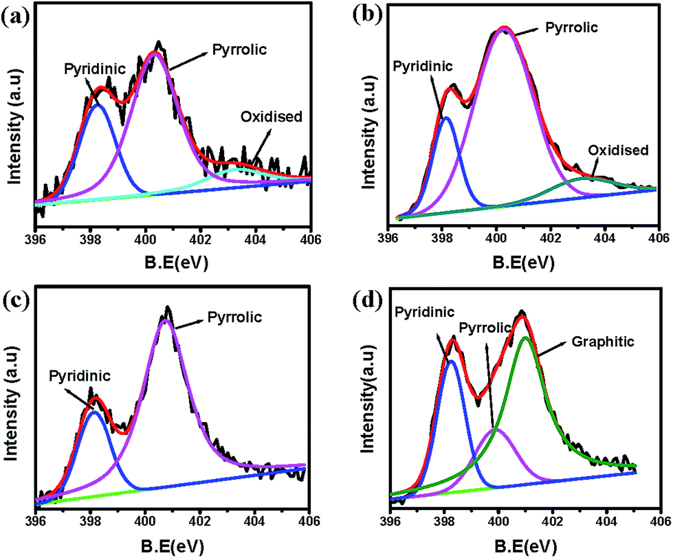 | ||
| Fig. 5 Deconvoluted N1s XPS peak for different pectin derived carbon samples (a) P0-00, (b) P0-SBA, (c) PU-SBA21 (d) PU-SBA11. | ||
As can be seen the nitrogen XPS is dominated by pyridinic (398.2 eV), and pyrrolic (400.2 eV) components both of which are essential for imparting the conductivity by participation in delocalisation.56 In addition to these the oxidised-nitrogen peak is observed between 403–405 eV in some samples. N1s spectrum of PU-SBA11 shows the emergence of graphitic nitrogen peak at 401.1 eV.57,58 The emergence of graphitic peak can be attributed to higher urea percentage which forces the carbon rings to assemble around the nitrogen atom.
Another interesting observation is that most of the nitrogen is trapped in the form of five membered pyrrolic rings. The predominance of pyrrolic and pyridinic nitrogen can be due to the urea-sugar hydrogen bonds which keep the nitrogen close to the ring giving more probability for collapse into an edge nitrogen than the central graphitic nitrogen. But with the increase in urea to pectin weight ratio, as in PU-SBA11, extra urea is left out from hydrogen bonding with –OH moieties of pectin. The free urea upon decomposition releases nitrogen which is surrounded by excited carbon radicals from all sides giving better probability for getting incorporated as graphitic nitrogen.
The pore structure was characterised by N2 adsorption–desorption BET tests. Fig. 6a and b show isotherm and pore size distribution for the templated and non-templated pectin derived carbons. The isotherms for all the samples show IUPAC type-IV behaviour.59,60 This type of isotherm is characteristic of mesoporous carbons. Other interesting feature of the isotherm is the hysteresis. The samples show a clear distinction in their hysteresis differing both in the extent and the profile of hysteresis.61
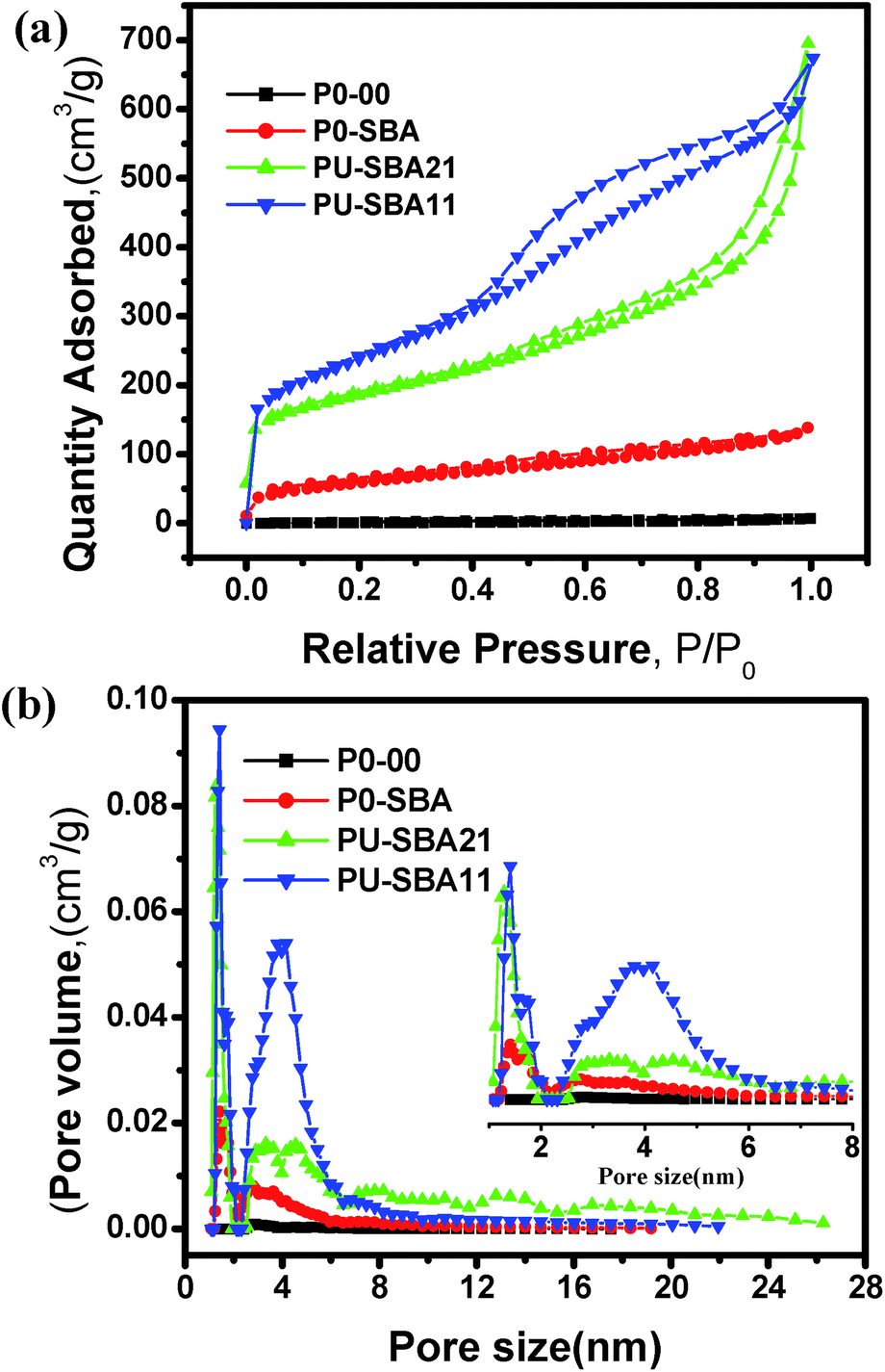 | ||
| Fig. 6 Surface area and pore analysis using N2 adsorption–desorption analysis: (a) N2 adsorption–desorption isotherms for different pectin derived carbons with different Hysteresis loops, (b) pore size distribution calculated using DFT calculation model. | ||
The isotherms for the pectin sample in Fig. 6 reveal that interconnected pore structure evolves with increased urea to pectin ratio.62,63 The hysteresis range for pectin derived samples, P0-00, P0-SBA, PU-SBA21, and PU-SBA11 is 0.1 < P/P0 < 1, 0.1 < P/P0 < 1, 0.4 < P/P0 < 1, and 0.5 < P/P0 < 0.9, respectively. Evolution of the hysteresis curves reveals the role of urea-assisted nitrogen doping in the morphology evolution, pore compaction and connectivity. The surface area is seen to have increased to 211 m2 g−1 for P0-SBA from 4 m2 g−1 for P0-00. This increase is because of the splitting the micro carbon to nano carbons by physical separation inside the template. Additionally, a surface area of 618 m2 g−1 was observed for PU-SBA21 which can be attributed to increase in urea to pectin ratio as compared to P0-SBA. Surface area of 837 m2 g−1 was observed for PU-SBA11 with further increase in the urea to pectin ratio. Correspondingly there has been an increase in the pore volume from 0.009 cm3 g−1 for P0-00 to 0.87 cm3 g−1 for PU-SBA1. Thus increase in the urea to pectin ratio in the synthesis has led to the morphology which allows for higher surface area and beneficial pore distribution as revealed by the BET analysis.
Fig. 6b compares the pore size distribution of the pectin derived samples. As can be seen there are two distribution maxima located at 1.45 nm and 4 nm. Templating sets the foundation for the peaks at 1.45 nm and 4 nm. The peak at 1.45 nm becomes intense with the increased urea percentage with negligible broadening, and the peak at 4 nm becomes intense and broadened. With the presence and broad distribution of mesopores with a mesoporosity of 83% centered at ∼4 nm and a microporosity of 17% at ∼1.5 nm in addition to the high surface area of 837 m2 g−1, the sample PU-SBA11 promises a high power delivery for the supercapacitor application. Table 1 summarises the Raman, BET, and XPS data. Comparing the different parameters listed in the table it can be concluded that PU-SBA11 should show the best electrochemical performance among all the samples.
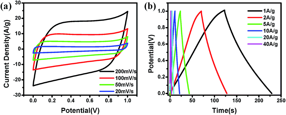
The electrochemical performance of carbon materials synthesized from pectin was checked in 1 M H2SO4 solution using three electrode assembly with calomel electrode as reference and platinum as the counter electrode. We first discuss the case of PU-SBA11 which was seen to perform best among all. Fig. 7 shows the electrochemical performance of the PU-SBA11 sample. Deviation from rectangular CV characteristics (Fig. 7a) is attributed to the pseudocapacitive charge transfer reactions due to nitrogen and oxygen functionalities that are especially highlighted in the three electrode measurements. Presence of these functionalities give the upper and lower wavy character to the otherwise nearly rectangular CV plot. Charge–discharge plots (Fig. 7b) show that capacitance of 285 F g−1 is acheived at 1 A g−1 which reduces to 210 F g−1 at 10 A g−1. Further high capacitance of 175 F g−1 is observed at extremely high current density of 40 A g−1. Capacitance retention at higher currents (capacitance vs. current density plot, Fig. 7c) has thus been quite remarkable in the present material with the figures of 74% retention of 1 A g−1 value at 10 A g−1. Further 62% retention was observed when the material was subjected to very extreme current load of 40 A g−1. The high capacitance values can mainly be attributed to one dimensional nanocarbon morphology.64–67 The particular morphology allows the maximum surface area to be presented to the electrolyte and extends the double layer over a larger surface area. The mesopores spaces help in solvent retention and thus help in keeping ions closer to the electrode material which in turn reflects in better performance at higher current.68
 | ||
| Fig. 7 Electrochemical characteristics of PU-SBA11 sample checked by performing CV, charge–discharge and impedance in 3-electrode assembly using 1 M H2SO4 as electrolyte and calomel electrode as reference electrode: (a) the CV plot of PU-SBA11 in the voltage range 0–1 V at a scan rate ranging from 5 mV s−1 to 200 mV s−1, (b) charge discharge plot of PU-SBA11 at varied current density from 1 A g−1 to 40 A g−1, (c) capacitance vs. current density plot showing very small loss of initial capacitance at higher current densities, (d) impedance spectra showing experimental Nyquist plot (shown by points) and corresponding simulated Nyquist plot (shown by solid blue line). Simulated circuit along with the zoomed high frequency region is shown in the inset. The various elements in the circuit are ESR (equivalent series resistance), Cdl (double layer capacitance), Rf (resistance element in series), and W (impedance element). | ||
The impedance analysis (Fig. 7d) shows a close fit between experimental Nyquist plot and the corresponding simulated Nyquist plot. The simulated plot was constructed based on the circuit shown in the inset of Fig. 7d and ESI Fig. S8.† The data was best fitted by a circuit containing, a resistance (Rf) in series with double layer capacitance Cdl and a Warburg impedance element (Z) in parallel to both these elements. Zoomed higher frequency region (Fig. 7d) is also shown in the inset. It can be seen that close fitting was observed with the chosen circuit. The ESR was calculated to be 1.61 Ω and the corresponding double layer capacitance of 207 mF cm−2 was observed. Further the nearly vertical rise (84°) towards lower frequency side shows the typical near-ideal capacitor behaviour. Fairly small length of Warburg element (45° projection) in Fig. 7d (inset) depicts the typical mesoporous nature of the carbon material. The cycling stability tests were performed at 10 A g−1 in 1 M H2SO4 in a three electrode system shown in Fig. S7.† The material showed a negligible (only 4%) capacitance loss after 2000 cycles.
The percentage of nitrogen doping and the extent of templating are reflected in the final electrochemical performance of pectin derived carbon forms. Fig. 8 shows a comparative 3-electrode electrochemical performance of all pectin derived carbons. Splitting the carbon framework into nano dimensions by templating has enhanced the capacitance by 10 folds as seen from Fig. 8a (CV plot) and Fig. 8b and c (charge–discharge plots). With the 3.8 at% nitrogen doping in PU-00 the capacitance has increased to 60 F g−1 which can be attributed to increase in conductivity. Structural and surface morphological differences brought about by different amounts of nitrogen doping in pectin derived carbons is reflected in their electrochemical performances.
 | ||
| Fig. 8 Shows the comparative electrochemical plots for all pectin derived carbons carried out in a three electrode assembly in 1 M H2SO4 with calomel as reference electrode: (a) shows the comparison of CV curves at scan rate of 50 mV s−1, (b) comparison of charge–discharge curves at 1 A g−1, (c) comparison of charge–discharge at 10 A g−1, and (d) comparison in the impedance behaviour of all the pectin derived samples (dots show the experimental data while as lines show the simulated data). | ||
Table T1 (ESI†) summarise the electro-chemical capacitance values of all the pectin and other gel derived carbons. The capacitance of 240 F g−1 was recorded for PU-SBA21 at 1 A g−1 in comparison to 285 F g−1 for PU-SBA11 at the same current density (Fig. 8b). Further from Fig. 8b and c, for PU-SBA11 the capacitance of 285 F g−1 at 1 A g−1 reduced to 210 F g−1 at 10 A g−1. For PU-SBA21 it reduced to 180 F g−1 from 240 F g−1. In the case of P0-SBA the capacitance of 225 F g−1 at 1 A g−1 dropped to 160 F g−1 at 10 A g−1. Fig. 8d compares the electrochemical impedance behaviour of all pectin derived carbons. The experimental and simulated data (derived from the equivalent circuit shown in Fig. S8†) are plotted together. Zoomed region in the inset of Fig. 8d shows the close fit. The impedance data generated, using equivalent circuit shown in Fig. S8† is summarised in Table T1 (ESI†). It can be seen PU-SBA11 stands tall with minimum ESR of 1.61 Ω and nearly vertical line in the low frequency region followed by PU-SBA21 and P0-SBA with ESR values of 2.07 Ω and 2.26 Ω, respectively. Other impedance parameters are also listed in the table. The ESR differences in case of pectin derived carbons can be related to ordered packing and substantial nitrogen concentration in the carbon lattice. The impedance data (Table T1 ESI†) shows a clear trend with the data collected from the CV and charge–discharge measurement. Further the polarization of the material is least in PU-SBA11 shown by vertical lines in the Nyquist plot in the low frequency region (Fig. 8d). As can be seen, low surface area carbons (P0-00, PU-00 and P0-SBA) show more polarization as compared to high surface area ones. These comparisons highlight the better performance of structurally superior and heavily nitrogen doped PU-SBA11 over other pectin derived carbon samples. Stability comparison of the three pectin derived carbons, PU-SBA11, PU-SBA21, P0-SBA was also carried out. Fig. S9† shows the data up to 1500 charge–discharge cycles. Fig. S9† shows stable charging and discharging capacities for PU-SBA11 with the retention of 97% capacity. Capacity retention of 78% and 65% was observed for PU-SBA21 and P0-SBA, respectively for the discharging case and capacity retention of 84% and 86% was observed for the charging case. One more noteworthy observation is that the Coulombic efficiencies which lie close to 100% (slightly lesser) for PU-SBA11 throughout the range, lie well below 90% for the PU-SBA21 and P0-SBA. These comparisons further highlight the superiority of PU-SBA11 over other pectin derived samples.
Two other natural gels agarose and alginate (sodium salt of alginate was used) were also tested for carbon synthesis through the same protocol as discussed in the Experimental section. The electrochemical performance of carbons varieties thus obtained, AgU-SBA11 and AlU-SBA11, was compared with that of PU-SBA11. Fig. 9 shows the comparison of the electrochemical performance (CV, CD and impedance) for these three doped carbon forms obtained from three different hydrogels. The CV plot (Fig. 9a) shows that capacitance loops of pectin are fattened in the region 0–0.4 V which is the small pseudocapacitance contribution from oxygen and nitrogen functionalities. The templating in their case has also led to increase in capacitance. It is interesting to compare the capacitance values (Fig. 9b) for the three gels. By the templating strategy the capacitance for PU-SBA11 (at 10 A g−1) has increased from 60 F g−1 to 210 F g−1. For AlU-SBA11 it is increased from 110 F g−1 to 160 F g−1, and for AgU-SBA11 it is increased from 10 F g−1 to 100 F g−1. Although there is an increase in capacitance by few-folds on templating in the case of agarose and alginate gels, the increase is not as high as in the case of pectin gel. The SEM images (Fig. S2 ESI†) also support the electrochemical observations. The formation of incomplete and disordered one dimensional threads of AgU-SBA11 and AlU-SBA11 is reflected in their electrochemical performance. This disordered structuring of nano threads may have been caused by inefficient infiltration of gel into the template. Electrochemical impedance parameters were simulated on the equivalent circuit shown in Fig. S8.† The data stands in line with the CV and charge–discharge results. ESR values of 2.5 Ω, 2.9 Ω were recorded for AlU-SBA11 and AgU-SBA11, respectively, which are higher than that of PU-SBA11.
 | ||
| Fig. 9 Electrochemical performance comparison of three natural gels, namely agarose, alginate and pectin, on a three assembly in 1 M H2SO4 with calomel as reference electrode: (a) compares the CV behaviour at scan rate of 50 mV s−1, and (b) compares charge–discharge characteristics at 10 A g−1. | ||
To check the symmetric characteristics of the PU-SBA material, the performance was checked in a two electrode dummy cell in 1 M H2SO4 (Fig. 10).
 | ||
| Fig. 10 Electrochemical two electrode performance of PU-SBA11 in 1 M H2SO4: (a) CV curves of PU-SBA11 at varied scan rates as high as 200 mV s−1 and as low as 20 mV s−1, (b) charge–discharge curves for PU-SBA11 at varied current densities ranging from lowest of 1 A g−1 to the highest of 40 A g−1. | ||
Nearly rectangular curve show fairly sharp charging and discharging sides, depicting nearly-ideal and superior capacitance behaviour. The two electrode capacitance of 230 F g−1 was observed at 1 A g−1 which decreased to 195 F g−1 at 10 A g−1 and to 140 F g−1 at 40 A g−1. The material provided 86% capacitance retention on going from 1 A g−1 to 10 A g−1 and 60% on going to 40 A g−1, which is comparable to well known and efficient carbon forms.
4. Conclusions
In Conclusion, a natural polymer hydrogel is used as a template precursor for the synthesis of porous carbon material for super-capacitor application. By use of the templating procedure, we were able to snip the carbon framework into inter-connected carbon threads. A particular morphology was seen to possess a surface area of 837 m2 g−1 with considerable fraction of mesopores (∼4 nm) with open type architecture having the pore volume of 0.87 cm3 g−1 and mesoporosity of 83%. Urea-assisted nitrogen doping has led to 7.0 at% doping, distributed in pyridinic, pyrrolic and graphitic forms which add to its advantage as a supercapacitive energy storage material. The material exhibits a three electrode capacitance of 285 F g−1 at 1 A g−1 with the capacitance retention of 74% at 10 A g−1 and 63% at 40 A g−1. Cycling stability is also commendable as the material exhibited only 4.0% loss after 2000 cycles at 10 A g−1. In a two electrode symmetric cell the material offered a capacitance of 230 F g−1 and delivered the energy of 7 W h kg−1 at 2.5 kW kg−1 in an aqueous medium.Acknowledgements
M. W. acknowledges the fellowship support from UGC-CSIR Govt. of India. The authors acknowledge funding support from CSIR's TAPSUN solar energy program. GP thanks Director, IISER, Pune, for allowing the project work to be performed at CSIR-NCL. MW also acknowledges Karthika. S and Raja. P, Ajay Kumar for instrumental support. MW pays a special thanks to Rohan Gokhale for his help in analysis.References
- M. Sevilla and R. Mokaya, Energy Environ. Sci., 2014, 7, 1250–1280 CAS.
- D. Pech, M. Brunet, H. Durou, P. Huang, V. Mochalin, Y. Gogotsi, P.-L. Taberna and P. Simon, Nat. Nanotechnol., 2010, 5, 651–654 CrossRef CAS PubMed.
- V. Augustyn, P. Simon and B. Dunn, Energy Environ. Sci., 2014, 7, 1597–1614 CAS.
- X. Lang, A. Hirata, T. Fujita and M. Chen, Nat. Nanotechnol., 2011, 6, 232–236 CrossRef CAS PubMed.
- P. Hao, Z. Zhao, J. Tian, H. Li, Y. Sang, G. Yu, H. Cai, H. Liu, C. P. Wong and A. Umar, Nanoscale, 2014, 6, 12120–12129 RSC.
- D. Mhamane, A. Suryawanshi, S. M. Unni, C. Rode, S. Kurungot and S. Ogale, Small, 2013, 9, 2801–2809 CrossRef CAS PubMed.
- X. Wang, Y. Zhang, C. Zhi, X. Wang, D. Tang, Y. Xu, Q. Weng, X. Jiang, M. Mitome, D. Golberg and Y. Bando, Three-dimensional strutted graphene grown by substrate-free sugar blowing for high-power-density supercapacitors, Nat. Commun., 2013, 4, 2905–2906 Search PubMed.
- L. Wei, M. Sevilla, A. B. Fuertes, R. Mokaya and G. Yushin, Adv. Energy Mater., 2011, 1, 356–361 CrossRef CAS PubMed.
- T. Yang, R. Zhou, D.-W. Wang, S. P. Jiang, Y. Yamauchi, S. Z. Qiao, M. J. Monteiro and J. Liu, Chem. Commun., 2012, 51, 2518–2521 RSC.
- D. Qu and H. Shi, J. Power Sources, 1998, 74, 99–107 CrossRef CAS.
- V. C. Almeida, R. Silva, M. Acerce, O. P. Junior, A. L. Cazetta, A. C. Martins, X. Huang, M. Chhowalla and T. Asefa, J. Mater. Chem. A, 2014, 2, 15181–15190 CAS.
- R. Gokhale, V. Aravindan, P. Yadav, S. Jain, D. Phase, S. Madhavi and S. Ogale, Carbon, 2014, 80, 462–471 CrossRef CAS PubMed.
- R. Gokhale, S. M. Unni, D. Puthusseri, S. Kurungot and S. Ogale, Phys. Chem. Chem. Phys., 2014, 16, 4251–4259 RSC.
- J. P. Paraknowitsch and A. Thomas, Energy Environ. Sci., 2013, 6, 2839–2855 CAS.
- Q. Shi, R. Zhang, Y. Lv, Y. Deng, A. A. Elzatahrya and D. Zhao, Carbon, 2014, 84, 335–346 CrossRef PubMed.
- D.-W. Wang, F. Li, Z.-G. Chen, G. Q. Lu and H.-M. Cheng, Chem. Mater., 2008, 20, 7195–7200 CrossRef CAS.
- J. Hou, C. Cao, F. Idrees and X. Ma, ACS Nano, 2015, 9, 2556–2564 CrossRef CAS PubMed.
- K. N. Wood, R. O'Hayre and S. Pylypenko, Energy Environ. Sci., 2014, 7, 1212–1249 CAS.
- Z. Li, Z. Xu, H. Wang, J. Ding, B. Zahiri, C. M. B. Holt, X. Tan and D. Mitlin, Energy Environ. Sci., 2014, 7, 1708–1718 CAS.
- L. Qie, W. Chen, H. Xu, X. Xiong, Y. Jiang, F. Zou, X. Hu, Y. Xin, Z. Zhang and Y. Huang, Energy Environ. Sci., 2013, 6, 2497–2504 Search PubMed.
- A. B. Fuertes and M. Sevilla, ACS Appl. Mater. Interfaces, 2015, 7, 4344–4353 CAS.
- D. Puthusseri, V. Aravindan, B. Anothumakkool, S. Kurungot, S. Madhavi and S. Ogale, Small, 2014, 10, 4395–4402 CAS.
- W. Qian, F. Sun, Y. Xu, L. Qiu, C. Liu, S. Wang and F. Yan, Energy Environ. Sci., 2013, 7, 379–386 Search PubMed.
- M. Wahid, G. Parte, D. Phase and S. Ogale, J. Mater. Chem. A, 2014, 3, 1208–1215 Search PubMed.
- M. Wahid, D. Puthusseri, D. Phase and S. Ogale, Energy Fuels, 2014, 28, 4233–4240 CrossRef CAS.
- J. Wang and S. Kaskel, J. Mater. Chem., 2012, 22, 23710–23725 RSC.
- L. Wei, M. Sevilla, A. B. Fuertes, R. Mokaya and G. Yushin, Adv. Funct. Mater., 2011, 22, 827–834 CrossRef PubMed.
- Y. S. Yun, S. Y. Cho, J. Shim, B. H. Kim, S.-J. Chang, S. J. Baek, Y. S. Huh, Y. Tak, Y. W. Park, S. Park and H.-J. Jin, Adv. Mater., 2013, 25, 1993–1998 CrossRef CAS PubMed.
- M. P. Bichat, E. Raymundo-Piñero and F. Béguin, Carbon, 2010, 48, 4351–4361 CrossRef CAS PubMed.
- M. Biswal, A. Banerjee, M. Deo and S. Ogale, Energy Environ. Sci., 2013, 6, 1249–1259 CAS.
- D. Puthusseri, V. Aravindan, S. Madhavi and S. Ogale, Energy Environ. Sci., 2013, 7, 728–735 Search PubMed.
- E. Raymundo-Piñero, M. Cadek and F. Béguin, Adv. Funct. Mater., 2009, 19, 1032–1039 CrossRef PubMed.
- M. Sevilla and A. B. Fuertes, ACS Nano, 2014, 8, 5069–5078 CrossRef CAS PubMed.
- P. Yadav, A. Banerjee, S. Unni, J. Jog, S. Kurungot and S. Ogale, ChemSusChem, 2012, 5, 2159–2164 CrossRef CAS PubMed.
- F. Goettmann, A. Fischer, M. Antonietti and A. Thomas, Angew. Chem., Int. Ed., 2006, 45, 4467–4471 CrossRef CAS PubMed.
- S. H. Joo, S. J. Choi, I. Oh, J. Kwak, Z. Liu, O. Terasaki and R. Ryoo, Nature, 2001, 412, 169–172 CrossRef CAS PubMed.
- S. Jun, S. H. Joo, R. Ryoo, M. Kruk, M. Jaroniec, Z. Liu, T. Ohsuna and O. Terasaki, J. Am. Chem. Soc., 2000, 122, 10712–10713 CrossRef CAS.
- A. Kumar, G. Hegde, S. A. B. A. Manaf, Z. Ngaini and K. V. Sharma, Chem. Commun., 2014, 50, 12702–12705 RSC.
- R. Ruiz-Rosas, M. J. Valero-Romero, D. Salinas-Torres, J. Rodríguez-Mirasol, T. Cordero, E. Morallón and D. Cazorla-Amorós, ChemSusChem, 2014, 7, 1458–1467 CrossRef CAS PubMed.
- R. Ryoo, S. H. Joo and S. Jun, J. Phys. Chem. B, 1999, 103, 7743–7746 CrossRef CAS.
- F. Chen, L. Huang and Q. Li, Chem. Mater., 1997, 9, 2685–2686 CrossRef CAS.
- T.-W. Kim, F. Kleitz, B. Paul and R. Ryoo, J. Am. Chem. Soc., 2005, 127, 7601–7610 CrossRef CAS PubMed.
- F. Kleitz, S. Hei Choi and R. Ryoo, Chem. Commun., 2003, 2136–2137 RSC.
- R. van Grieken, J. Iglesias, V. Morales and R. A. García, Microporous Mesoporous Mater., 2010, 131, 321–330 CrossRef CAS PubMed.
- P. Yang, D. Zhao, B. F. Chmelka and G. D. Stucky, Chem. Mater., 1998, 10, 2033–2036 CrossRef CAS.
- D. Zhao, P. Yang, N. Melosh, J. Feng, B. F. Chmelka and G. D. Stucky, Adv. Mater., 1998, 10, 1380–1385 CrossRef CAS.
- Y. Fan, P.-F. Liu, Z.-J. Yang, T.-W. Jiang, K.-L. Yao, R. Han, X.-X. Huo and Y.-Y. Xiong, Electrochim. Acta, 2015, 163, 140–148 CrossRef CAS PubMed.
- H. Yang and D. Zhao, J. Mater. Chem., 2005, 15, 1217–1231 CAS.
- Z. Zafar, Z. H. Ni, X. Wu, Z. X. Shi, H. Y. Nan, J. Bai and L. T. Sun, Carbon, 2013, 61, 57–62 CrossRef CAS PubMed.
- L. G. Bulusheva, A. V. Okotrub, I. A. Kinloch, I. P. Asanov, A. G. Kurenya, A. G. Kudashov, X. Chen and H. Song, Phys. Status Solidi B, 2008, 245, 1971–1974 CrossRef CAS PubMed.
- P. H. Matter, L. Zhang and U. S. Ozkan, J. Catal., 2006, 239, 83–96 CrossRef CAS PubMed.
- D. Hulicova-Jurcakova, M. Seredych, G. Q. Lu and T. J. Bandosz, Adv. Funct. Mater., 2009, 19, 438–447 CrossRef CAS PubMed.
- E. Desimoni, G. I. Casella, A. Morone and A. M. Salvi, Surf. Interface Anal., 1990, 15, 627–634 CrossRef CAS PubMed.
- O. Munjeri, J. H. Collett and J. T. Fell, J. Controlled Release, 1997, 46, 273–278 CrossRef CAS.
- G. Dongowski, B. Schnorrenberger, M. Platzer, M. Schwarz and R. Neubert, Int. J. Pharm., 1997, 158, 99–107 CrossRef CAS.
- A. G. Pandolfo and A. F. Hollenkamp, J. Power Sources, 2006, 157, 11–27 CrossRef CAS PubMed.
- C. Morant, J. Andrey, P. Prieto, D. Mendiola, J. M. Sanz and E. Elizalde, Phys. Status Solidi A, 2006, 203, 1069–1075 CrossRef CAS PubMed.
- T. Sharifi, F. Nitze, H. R. Barzegar, C.-W. Tai, M. Mazurkiewicz, A. Malolepszy, L. Stobinski and T. Wagberg, Carbon, 2012, 50, 3535–3541 CrossRef CAS PubMed.
- S. Brunauer, L. S. Deming, W. E. Deming and E. Teller, J. Am. Chem. Soc., 1940, 62, 1723–1732 CrossRef CAS.
- Y. Gogotsi, A. Nikitin, H. Ye, W. Zhou, J. E. Fischer, B. Yi, H. C. Foley and M. W. Barsoum, Nat. Mater., 2003, 2, 591–594 CrossRef CAS PubMed.
- G. G. Stavropoulos and A. A. Zabaniotou, Microporous Mesoporous Mater., 2005, 82, 79–85 CrossRef CAS PubMed.
- Y. Yan, Y. Hoshino, Z. Duan, S. R. Chaudhuri and A. Sarkar, Chem. Mater., 1997, 9, 2583–2587 CrossRef CAS.
- H. J. Shin, R. Ryoo, M. Kruk and M. Jaroniec, Chem. Commun., 2001, 349–350 RSC.
- L.-F. Chen, X.-D. Zhang, H.-W. Liang, M. Kong, Q.-F. Guan, P. Chen, Z.-Y. Wu and S.-H. Yu, ACS Nano, 2012, 6, 7092–7102 CrossRef CAS PubMed.
- Y.-H. Hsu, C.-C. Lai, C.-L. Ho and C.-T. Lo, Electrochim. Acta, 2014, 127, 369–376 CrossRef CAS PubMed.
- X. Yan, Y. Liu, X. Fan, X. Jia, Y. Yu and X. Yang, J. Power Sources, 2013, 248, 745–751 CrossRef PubMed.
- T. Zhang, C. H. J. Kim, Y. Cheng, Y. Ma, H. Zhang and J. Liu, Nanoscale, 2015, 7, 3285–3291 RSC.
- H. Wang, Z. Xu, A. Kohandehghan, Z. Li, K. Cui, X. Tan, T. J. Stephenson, C. K. King'ondu, C. M. B. Holt, B. C. Olsen, J. K. Tak, D. Harfield, A. O. Anyia and D. Mitlin, ACS Nano, 2013, 7, 5131–5141 CrossRef CAS PubMed.
Footnote |
| † Electronic supplementary information (ESI) available: FE-SEM images of SBA-15, FE-SEM image comparison of carbon derived from pectin, alginate and agarose, XPS survey and carbon spectra of all pectin derived carbons, EDS spectra of three pectin derived carbon forms, chemical structural formulae of three natural gels, cycling stability plot of PU-SBA11, comparative cyclic stability of some pectin derived carbons, electrochemical circuit fitted to impedance data, table comparing the electrochemical data for different gel derived carbon forms. See DOI: 10.1039/c5ra05107j |
| This journal is © The Royal Society of Chemistry 2015 |