The monitoring of coating health by in situ luminescent layers
Y. Hea,
S. C. Wang*a,
F. C. Walsha,
W. S. Lib,
L. Heb and
P. A. S. Reedc
aNational Centre for Advanced Tribology at Southampton (nCATS), University of Southampton, SO17 1BJ, UK. E-mail: wangs@soton.ac.uk; Tel: +44 (0)2380594638
bState Key Laboratory of Advanced Nonferrous Materials, Lanzhou University of Technology, Lanzhou 730050, China
cEngineering Materials and Surface Engineering, University of Southampton, SO17 1BJ, UK
First published on 5th May 2015
Abstract
The monitoring of coating health is crucial for the assessment of wear life in service. Electrodeposition is one of most common methods used for producing coatings including composite layers by electrophoretic deposition of particles into a growing metal electrodeposit. A new luminescent Ni coating containing an embedded, blue-emitting rare-earth mixed metal oxide (BaMgAl11O17:Eu2+) phosphor has been electrodeposited successfully from an aqueous electrolyte. Two types of surfactants were utilised to study the effective co-deposition of these particles into the nickel matrix. The surfactants of non-ionic PEG (polyethylene glycol) and cationic CTAB (cetyl trimethylammonium bromide) were observed to increase the particle content in the deposit from zero to 4.6% and 11.5%, respectively. A mixture of these two surfactants produced the highest particle embedded coverage (15.6%). The feasibility of luminescent layers in monitoring the wear of coatings has also been verified in the final part of the manuscript.
1. Introduction
Surface coatings play an important role in prolonging the lifetime of components by enhancing mechanical performance. Due to varying environments, it is unavoidable that any area in intermittent contact is worn or corroded faster than the less contacted area, which may result in pre-failure, catastrophic damage or loss. Where it is expensive to replace the whole workpiece or costly in terms of conventional inspection and downtime maintenance, there is a clear benefit in extending the coatings' life safely. All of these depend on developing a health sensing system within coatings to monitor deterioration during their use.Use of luminescence in coatings was first proposed in 2004.1 Physical vapour deposition (PVD) was first used to sputter a phosphorescent/fluorescent film which emitted a constant glow under an ultraviolet (UV) light. Erbium- and samarium-doped yttria stabilized zirconia layers, for example, were deposited in thermal barrier coatings.2–4 The disadvantage of this method is its reliance on expensive and less flexible facilities with limited deposition rates. In addition, the produced film is in general too thin to be used as coating protection in wider engineering applications.
Aqueous deposition, instead of non-aqueous deposition, achieves a reasonable balance between cost and performance. Electroless deposition and electrodeposition are two classical approaches. The former has an advantage over non-line-of-sight coatings but suffers from unstable solutions as well as a slow rate process with a maximum thickness of a few microns, which again limits its applications. In contrast, electrodeposition has a much faster deposition rate and allows better control of the deposition process. It is one of most successful methods for producing composite layers by electrophoretic deposition of particles into a growing metal electrodeposit,5–7 despite the challenges including the dispersion of the particles in the bath and particle adhesion ability to electrode surface. The thickness can be well controlled from a few nanometres to several hundred micrometres.8 A review of the literature, however, reveals few successful instances of preparation of luminescent coatings by aqueous deposition. One limited report is on electrolessly deposited luminescent nickel coating.9–11 The second case is electrodeposited nickel and rare-earth phosphors using an ionic liquid bath of dimethylsulfone and NiCl2.12 The plating was carried out at a temperature of 130 °C which would limit potential industry applications as such a high bath temperature is unfavourable. Furthermore, ionic liquids are expensive to scale up and can involve supply, handling and disposal problems, making their use generally unattractive to industry.
The present research aims to develop a Ni coating embedded with phosphorescent particles (BaMgAl11O17:Eu2+, BAM) which are used to detect the wear condition of coatings simply using an ultraviolet light. The challenge for electrodeposition in an aqueous solution is that the rare earth phosphors (metal oxides) are usually micron size, which are difficult to attach to the electrode surface.13 Two types of surfactants – cationic (cetyltrimethylammonium bromide, CTAB) and non-ionic (polyethylene glycol, PEG) were studied for enhancement of particle deposition. The particle concentrations were also investigated by steady-state and time-resolved luminescence spectroscopy to optimise the emission intensities.
2. Experimental procedure
All chemicals used were analytical grade to minimize the effect of impurities. The electrolyte solution for nickel plating contained NiSO4·6H2O (250 g dm−3), NiCl2·4H2O (45 g dm−3) and H3BO3 (40 g dm−3) in distilled water. The pH for the plating bath was adjusted by H2SO4 or NaOH to 4.5 ± 0.5, as this value has been reported to induce the lowest internal stress during Ni electroplating.14,15 The bath was mixed under ultrasonic agitation. The as-received luminescent particles were BaMgAl11O17:Eu2+ (BAM) of 2–3 μm in diameter. BAM is an important blue-emitting phosphor and has found widespread applications in plasma display panels and fluorescent lamps. 0.3 mmol dm−3 polyethylene glycol (PEG-WM 6000) and/or 0.3 mmol dm−3 cetyl trimethylammonium bromide (CTAB) were added in the electrolyte solution with 5 g dm−3 BAM particles to study the effect of non-ionic and cationic surfactant on the co-deposition of BAM particles.An AISI 1002 mild steel plate was chosen for the electrodeposition substrate. Prior to deposition, the substrate was ground with 800 grit SiC paper followed by water flushing. The substrate was immersed into 10% HCl for 10 s, then rinsed by distilled water. A pure nickel plate was used as the anode. The electrodeposition was performed with magnetic stirring (5 mm diameter, 15 mm long, PTFE-coated magnetic stirrer) at 45 ± 2 °C and a current density of 4 A dm−2 for 45 min to produce a coating thickness of 19–35 μm.
Linear sweep voltammetry (LSV) measurements were performed by an Autolab PGSTA30 system to determine a suitable potential range for deposition. The working electrode was a 3 mm thick mild steel plate of dimensions 10 mm × 40 mm. The counter electrode was a platinum mesh electrode having the same overall dimensions. A saturated calomel electrode (SCE) was used for the reference electrode. Measurements were carried out using a conventional, three-electrode cell in the electrolytic bath at a linear potential scan rate of 10 mV s−1 over a potential range of 0 to −1.2 V vs. SCE.
The morphology of the BAM particles and the composite coatings was observed using a scanning electron microscope (SEM) JEOL JSM-6500F at the Engineering Electron Microscopy Centre, Southampton University. The elemental analysis was carried by Oxford energy dispersive spectrometry (EDS). The area coverage of particles in the coating and particle size distribution were evaluated using ImageJ image processing software based on the SEM backscattered electron images (BEI). Photoluminescence excitation and emission spectra were acquired at λem = 450 nm and λex = 330 nm by visible-UV/fluorescence spectrometers (slitex = 5 nm, slitem = 5 nm). The hardness of composite coatings was carried out using a Vickers' microhardness instrument at an applied load of 100 g for 15 s, with five measurements on each sample.
A reciprocating TE-77 tribometer (Phoenix, UK) was used to evaluate the friction behaviour in laboratory air with a relative humidity of 40–50% at 25 °C. The counter body was an AISI-52100 stainless steel ball (diameter 6 mm) with a hardness of 700 HV. The studies were carried out (avoiding coating failure) on a load of 14 N with an initial Hertzian contact pressure of 0.31 GPa, a sliding frequency of 1 Hz and a sliding stroke of 2.69 mm. The total sliding times were 30 min and 90 min respectively for the Ni/BAM coating and double layer coating system (Ni + Ni/BAM). The wear track was analysed by both Alicona infinite focus optical microscopy and fluorescent microscopy.
3. Results
3.1 Luminescent coating
In this study, two types of luminescent coatings were designed. One is to incorporate luminescent particles into the functional top layer (Fig. 1a) and another is as an underlayer, as shown in Fig. 1b. These luminescent particles appear normal under visible light, but emit colours under an ultraviolet (UV) light. For the coating in Fig. 1a, the disappearance of the luminescence under UV light is a sign of coating damage and thus recoating may be required. In comparison, the observation of coloured light in Fig. 1b indicates that the functional coating has worn/corroded away. With a portable UV light/torch, the emitting coating can be inspected periodically even when the component part is still in service.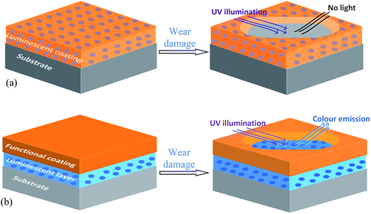 | ||
| Fig. 1 Schematic diagrams showing luminescent particles codeposited as top layer in (a) or interlayer in (b), and the coating appearance in the damaged area. | ||
3.2 Effect of surfactants on the co-electrodeposition
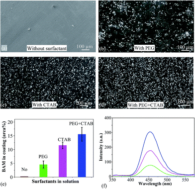
The majority of the as-received BAM particles were spheroidal, with an average size of 2 μm. Electrodeposited coatings were prepared in the basic electrolyte with and without surfactants. In the absence of surfactants, the coating showed a smooth surface (Fig. 2a). EDS confirmed it to be pure nickel where BAM particles were barely observed. In the PEG electrolyte bath, an average 4.6% area coverage of BAM particles were co-deposited with the nickel matrix but these were not uniformly distributed, as shown in Fig. 2b. In the electrolyte bath with CTAB, the BAM powders were well embedded in the Ni coatings (Fig. 2c) and coverage reached 11.5%. In the electrolyte bath with addition of both PEG + CTAB surfactants, the deposit consisted of denser particles, as shown in Fig. 2d. The area coverage of particles was found to average at 15.6% which is almost the sum of those from solutions with a single surfactant as shown in Fig. 2e. Fig. 2f shows the photoluminescence spectra of composite coatings excited by 330 nm UV light. The emission wavelength of Ni/BAM samples was ca. 452 nm, which corresponds to the transition of Eu2+ ion from its lowest 5d excited state to the 4f ground state. The luminescence intensity of the coating deposited with PEG + CTAB addition was 4 times higher than the coating from a bath containing PEG.3.3 Voltammetry study of co-electrodeposition
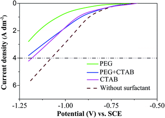
Linear sweep voltammetry was used to characterize the electrochemical performance of the electrodes in the composite electrodeposition baths. Fig. 3 records the cathodic LSV curves for Ni/BAM deposition in the solutions in the presence or absence of surfactants. Without surfactants, Ni deposition started at a potential of approximately −0.58 V vs. SCE. As the potential became more negative than −0.83 V, the current density increased rapidly due to the secondary reaction of hydrogen evolution.With the addition of PEG, the potential shifted significantly toward negative values at a given current density. At a current density of 4 A dm−2, the potentials were −1.1 V and −1.3 V for the coatings from the baths without surfactant and with PEG addition. The high negative overpotential accompanied by intensive hydrogen evolution, caused a number of pores and eventually affected coating quality. As a result, PEG was not considered as a sole surfactant. In contrast, the two coatings, produced from the baths with the addition of CTAB and PEG + CTAB, showed potentials of approximately −1.2 V at 4 A dm−2. And the mixed surfactants were more effective for the codeposition of nickel and luminescent particles.
3.4 Mechanical and tribological properties
The influence on friction, wear rate and hardness of the added BAM of the coating compared to the bare Ni coating has also been investigated. The coefficients of friction (sliding at ambient air) of coatings increase with the added BAM, from an average of 0.55 for the bare Ni coating to 0.7 for the 15.6% BAM coating, as shown Fig. 4a. The sliding wear rates in ambient air are decreased from 4.8 × 10⁻⁴ mm3 N−1 m−1 for the bare Ni coating to half this value for the 15.6% BAM coating, and the corresponding hardness increases from an average of 450 HV for the bare Ni coating to 599 HV for the 15.6% BAM coating, as shown in Fig. 4b. The strengthening effect could be explained in terms of an Orowan hardening mechanism,16 where dislocations bow around BAM particles which act as dislocation pinning sites resulting in an increase in the flow stress. The wear rates are inverse to the corresponding hardnesses, hence obeying the Archard wear equation for the cases of sliding and abrasion wear. It is evident that the codeposited particles improve the wear resistance and strengthen the coatings, but result in higher friction coefficients. The result is not unexpected as it is a general rule that a higher hardness will result in a reduced lower wear rate.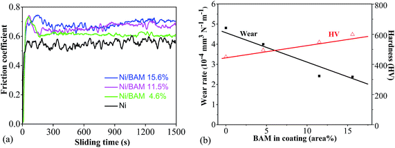 | ||
| Fig. 4 (a) Coefficient of friction against sliding time for the Ni and Ni/BAM coatings; (b) wear rate and hardness of Ni/BAM coatings vs. BAM content in coating. | ||
4. Discussion
As indicated in Fig. 2, the surfactants are crucial to deposit satisfactory ceramic–metal composite coatings: with the addition of PEG, CTAB and PEG + CTAB, the area coverages of the embedded BAM particles have increased from nil without surfactant to 4.6%, 11.5% and 15.6%, respectively.For an inert particle in a bath to grow into the deposit involves convection, diffusion and then adsorption and reduction at the electrode surface, before such particles can be embedded in the metal.17–19 When the force of adhesion is strong enough to resist the shear force due to gravity, particles begin to be incorporated into the growing metal layer. In this study, for micron size (>1 μm) particles with a high density (>3.2 g cm−3) in the absence of a surfactant, the gravitational force appears larger than the sum of other forces, hence the majority of the particles can't attach to the electrode surface and no effective incorporation of particles can occur (Fig. 5a). Thus, without surfactant, the particles tend to settle and agglomerate at the bottom of the electrolyte.
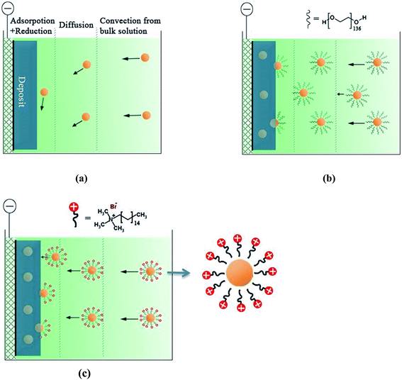 | ||
| Fig. 5 Schematic illustration of the codeposition process of particles in electrolyte with (a) no surfactant, (b) PEG or (c) CTAB. | ||
PEG (Mn = 6000) is a non-ionic surfactant with a long chain structure H–(O–CH2–CH2)136–OH. With such a structure PEG is hydrophilic in water (H–OH). In the electrolyte solution, The OH− of PEG will migrate into the BAM particles and H+ will orient towards the water (Fig. 5b). The adsorbed PEG layer can provide steric separation and its hydrophilicity can inhibit the particles from merging into larger aggregates, so less sedimentation is expected. With the applied electricity, the hydrogen-bond of PEG will be attracted strongly by existing electrons in the cathode. The electronic force will hold the particles on the electrode surface longer and this enhances the incorporation of particles into the metal matrix.
CTAB molecule, (C16H33)N(CH3)3Br, is a long chain cationic surfactant. It consists of a hydrophobic tail and a non-charged hydrophilic head (as shown in Fig. 5c): the former part preferentially adsorbs on particles, whereas the latter part keeps away from the particles.20,21 This electrostatic repulsion helps to produce a stable dispersion in the electrolyte. As a cationic surfactant, CTAB can not only improve the stability of particle suspension but also charge the non-conductive particles positively via electrostatic adsorption.22 Therefore, the cationic particles will be attracted strongly to the cathode surface under the applied potential. This helps explain why the particle area coverage with CTAB was 6.9% higher than that with PEG.
With the addition of both PEG and CTAB, the area coverage of BAM particles was 15.6% which is almost the sum of the sole surfactant effects. It indicates the additive effect of CTAB and PEG operating on the particle surface, so the embedding of ceramic particles can be maximised by the suspension enhanced by PEG and the increase of the adhesion force between the cationic particles and the cathode by CTAB.
The non-ionic surfactant PEG and the cationic surfactant CTAB have different effects on the electrodeposition reaction, as indicated in the LSV curves of Fig. 3. The adsorption of the PEG onto the electrode surface took up some available sites and made charge transfer unavailable at these sites,23 the resistance will increase and accordingly the voltage i.e. overpotential. A high negative overpotential usually results in intensive hydrogen evolution which may block the deposition of particles and Ni ions. The situation is quite different for CTAB, as it is an active cationic surfactant.24 If the applied deposition potential becomes more negative than its reduction potential, the CTAB molecule (with or without BAM connected) on the electrode will be reduced and the CTAB in solution will diffuse toward the cathode surface, which compensates the curve shift in Fig. 3. As a consequence, it is more effective in enhancing the deposition of particles and a higher percentage of BAM can be achieved during the composite electrodeposition process.
With the addition of the two surfactants, the LSV of Ni/BAM electrodeposition is similar to that from a bath containing CTAB in Fig. 3. This may indicate that the individual particle is covered by a mixture of CTAB and PEG. It also explains why the particle area coverage is close to the sum of those by achieved individually by CTAB and PEG additions. The anionic/non-ionic surfactant combination has been reported to improve the embedment of particles in other composite plating systems such as Ni/PTFE (polytetrafluoroethylene polymer composite), Ni–P/PTFE or Ni–TiO2–SiO2.25–27
5. Applications
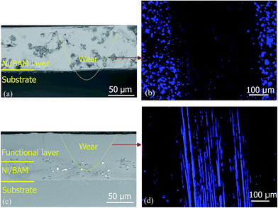
Two types of luminescent coatings in Fig. 1 have been successfully prepared. Fig. 6 shows the cross section view and the corresponding worn surface under UV. For the top layer with the embedded luminescent particles as shown in Fig. 6a, the worn through area on the coating did not show any light emission while the surrounding area showed clear blue-light emission (Fig. 6b). For the luminescent particles embedded in the interlayer (Fig. 6c), the illumination occurs in the worn through surface (Fig. 6d). These layers can be extended further to produce multiple colour layers including red, green and blue for functional coatings potentially allowing different wear depths to be sensed.6. Conclusions and further work
The study has demonstrated the use of embedded luminescent particles to monitor coating health. Non-ionic PEG and cationic CTAB surfactants have been used to successfully incorporate BAM particles into nickel coatings using an aqueous nickel plating electrolyte, with area coverages of 4.6% and 11.5%, respectively. The improvement by PEG is due to the surfactants helping the suspension of the particle in the bath by adsorbing on its surface and increasing steric hindrance. The cationic surfactant CTAB shows a higher impact on the successful incorporation of particles in the electrodeposited layer as it can change the net charge on the particles and increases the migration force to the cathode. A combination of CTAB + PEG electrolyte additives offered the best area coverage of BAM particles in the nickel coatings up to 15.6% due to the additive, synergistic effect of the mixed surfactants.Having demonstrated the principle of wear detection via embedded luminescent particles in a composite metal–ceramic particle electrodeposit, it should be possible to extend the technique in several ways for monitoring of surfaces undergoing coating wear, damage or removal. For example, (a) partial removal of a coating due to wear might be followed by continuous reduction of phosphorescent intensity, (b) a multi-layered coating with different coloured phosphors in successive, controlled thickness layers could be used or (c) a continuously changing phosphor level in a compositionally modulated coating could be used to produce a phosphorescent signal which is depth sensitive.
A long-term goal of this work is to develop a sensing system based on coatings in order to monitor deterioration during service. The damage has been analysed here using infinite focus optical microscopy and fluorescent microscopy under laboratory conditions. Recently introduced UV fluorescent probes can be used for accurate on-site monitoring. Such probes can be lightweight, compact, and handheld, hence suitable for field application.
Acknowledgements
The authors acknowledge financial support by the China Scholarship Council (CSC), the Faculty of Engineering and the Environment at University of Southampton, the Royal Society (IE111270) and the Royal Academy of Engineering (1314RECI080). The authors thank Dr Hansjürgen Schuppe at the University of Southampton for assistance with the fluorescent imaging. The authors acknowledge valuable suggestions from referees during the preparation of the manuscript.References
- M. M. Gentleman and D. R. Clarke, Surf. Coat. Technol., 2004, 188, 93 CrossRef PubMed
.
- J. I. Eldridge and T. J. Bencic, Surf. Coat. Technol., 2006, 201, 3926 CrossRef CAS PubMed
.
- C. Muratore, D. R. Clarke, J. G. Jones and A. A. Voevodin, Wear, 2008, 265, 913 CrossRef CAS PubMed
.
- Y. J. Mi, J. Q. Wang, Z. G. Yang, H. G. Wang, Z. F. Wang and S. R. Yang, RSC Adv., 2014, 4, 39743 RSC
.
- F. C. Walsh and C. Ponce de Leon, Trans. Inst. Met. Finish., 2014, 92, 83 CrossRef CAS PubMed
.
- Y. Liu, M. S. Ata, K. Shi, G.-z. Zhu, G. A. Botton and I. Zhitomirsky, RSC Adv., 2014, 4, 29652 RSC
.
- Y. M. Wang, D. D. Zhao, Y. Q. Zhao, C. L. Xu and H. L. Li, RSC Adv., 2012, 2, 1074 RSC
.
- C. T. J. Low, R. G. A. Wills and F. C. Walsh, Surf. Coat. Technol., 2006, 201, 371 CrossRef CAS PubMed
.
- Surface Technology Inc., Nickel, 2009, 24, 9 Search PubMed
.
- M. D. Feldstein, Met. Finish., 1999, 97, 87 CrossRef CAS
.
- M. Maloney, US Pat., 6117560, 2000
.
- M. Ganapathi, S. V. Eliseeva, N. R. Brooks, D. Soccol, J. Fransaer and K. Binnemans, J. Mater. Chem., 2012, 22, 5514 RSC
.
- L. Stappers and J. Fransaer, J. Electrochem. Soc., 2006, 153, C472 CrossRef CAS PubMed
.
- Y. Tsuru, M. Nomura and F. R. Foulkes, J. Appl. Electrochem., 2000, 30, 231 CrossRef CAS
.
- C. Ma, S. C. Wang, L. P. Wang, F. C. Walsh and R. J. K. Wood, Wear, 2013, 306, 296 CrossRef CAS PubMed
.
- S. C. Wang, Z. Zhu and M. J. Starink, J. Microsc., 2005, 217, 174 CrossRef CAS PubMed
.
- N. Guglielmi, J. Electrochem. Soc., 1972, 119, 1009 CrossRef CAS PubMed
.
- J. P. Celis, J. R. Ross and C. Buelens, J. Electrochem. Soc., 1987, 134, 1402 CrossRef CAS PubMed
.
- J. Fransaer, J. P. Celis and J. R. Ross, J. Electrochem. Soc., 1992, 139, 413 CrossRef CAS PubMed
.
- A. Gomes and M. I. da Silva Pereira, Electrochim. Acta, 2006, 51, 1342 CrossRef CAS PubMed
.
- L. Chen, L. Wang, Z. Zeng and J. Zhang, Mater. Sci. Eng., A, 2006, 434, 319 CrossRef PubMed
.
- A. Hovestad and L. J. J. Janssen, J. Appl. Electrochem., 1995, 25, 519 CrossRef CAS
.
- S. J. Kim, D. Joseell and T. P. Moffat, J. Electrochem. Soc., 2006, 153, 616 CrossRef PubMed
.
- L. M. Wang, J. Electrochem. Soc., 2009, 156, 204 CrossRef PubMed
.
- Z. A. Hamid and M. A. Omar, Anti-Corros. Methods Mater., 1999, 46, 212 CrossRef CAS
.
- I. R. Mafi and C. Dehghanian, Appl. Surf. Sci., 2011, 257, 8653 CrossRef CAS PubMed
.
- H. X. Guo, X. P. Zhao, H. L. Guo and Q. Zhao, Langmuir, 2003, 19, 9799 CrossRef CAS
.
| This journal is © The Royal Society of Chemistry 2015 |

