
Triple bond-modified anthracene sensitizers for dye-sensitized solar cells: a computational study†
Ruangchai Tarsanga,
Vinich Promarakb,
Taweesak Sudyoadsuka,
Supawadee Namuangrukc,
Nawee Kungwand,
Pipat Khongprachae and
Siriporn Jungsuttiwong*a
aCenter for Organic Electronic and Alternative Energy, Department of Chemistry and Center of Excellence for Innovation in Chemistry, Faculty of Science, Ubon Ratchathani University, Ubon Ratchathani 34190, Thailand. E-mail: siriporn.ubu@gmail.com; Fax: +66 4 528 8379; Tel: +66 4 535 3400 ext. 4510
bSchool of Chemistry and Center of Excellence for Innovation in the Chemistry, Institute of Science, Suranaree University of Technology, Nakhon Ratchasima 30000, Thailand
cNational Nanotechnology Center, National Science and Technology Development Agency, Klong Luang, Pathumthani 12120, Thailand
dDepartment of Chemistry, Faculty of Science, Chiang Mai University, Chiang Mai 50200, Thailand
eLaboratory for Computational and Applied Chemistry, Department of Chemistry, Faculty of Science, Kasetsart University, 50 Phaholyothin Rd., Ladyao, Jatujak, Bangkok 10900, Thailand
First published on 15th April 2015
Abstract
We performed a theoretical investigation on a series of organic dyes incorporating an anthracene moiety between a carbazole donor group and a cyanoacrylic acid acceptor, in which a triple bond (TB)-modified moiety acts as a π-conjugated linker. Density functional theory (DFT) and time-dependent DFT (TD-DFT) were applied to understand the electronic, photophysical, and electron injection properties of the dyes. We found that optimized anthracene structures lay almost perpendicular to the plane of the adjacent substituents. The introduction of a modified TB moiety significantly decreases the dihedral angle and results in a planar structure, which extends the length of the π-conjugated system to provide a broader absorption spectrum, the An4 dye exhibited the greatest red shift of the maximum absorption wavelength. Introduction of a TB moiety into the dye structure facilitates electron transfer from the donor and acceptor. The TB-modified dye structure has a significant effect on electron injection from the dye sensitizer to the TiO2 surface. Our results demonstrate that use of computational design can to help the experimentalist for looking out for future developments to identify TB-modified anthracene sensitizers for highly efficient solar cells.
1. Introduction
DSSCs have received extensive attention since the first report of high-efficiency dye-sensitized solar cells (DSSC) by O'Regan and Grätzel in 1991,1 DSSC manufacture requires relatively low-cost, facile processes compared to traditional silicon-based solar cells. Thus, the conversion of sunlight to electricity using DSSCs is a promising source of affordable renewable energy.2 During recent decades, there have been numerous reports of DSSC-based investigations, with over 1000 articles published by the end of the 20th century, and this trend continues to grow.3 Metal-free organic-dye-based sensitizers show promise for DSSC applications, and there is active experimental and theoretical research into the development of organic-dye-based DSSC cells with high solar-to-electricity conversion efficiency.4–6The majority of research into metal-free organic dyes is concerned with the design of novel dye sensitizers, which are a key component in the DSSC working principle to harvest solar irradiation for converting light to electricity. The metal-free dye based on a donor–π-conjugated-acceptor (D–π–A) architecture can provide high-efficient photovoltaic performance,7 the highest record exceeding 11%.8 A variety of electron donating groups (D) have been reported, including triarylamine,9 coumarin,10 carbazole,11 fluorine,12 and phenothiazine.13,14 Three main electron acceptor groups (A) are used, namely, cyanoacrylic acid,15 carboxylic acid,16 and rhodanine-3-acetic acid.17
The presence of a π-conjugated linker in an organic sensitizer broadens the visible region absorption band by extending the length of the π-conjugation system. Structural modification of the π-conjugated linker can greatly improve DSSC performance.5,18 Researchers have varied π-conjugated bridges by using a series of acenes comprising polycyclic aromatic hydrocarbons with fused benzene rings in a rectilinear arrangement. In particular, an anthracene moiety, which consists of three fused benzene rings, shows promise as an acene-modified linker. In recent years, Fan et al.19 reported a series of dye sensitizers with acene-modified linkers, from benzene to pentacene. Fan reported that the presence of an anthracene unit provided several advantages, including good light-harvesting efficiency (LHE) and improved electron injection properties. Thus, anthracene shows promising as a linker component to provide a highly efficient dye sensitizer for DSSC applications. Additionally, the anthracene group outperforms other acene-modified linkers in the benzene to pentacene series,20 with an overall efficiency of approximately 5.44%.
Generally, there are two ways to derivatize anthracene as a π-conjugated linker; substituent groups can be introduced at either the 9,10- or the 2,6-positions on the anthracene unit to provide alternative conjugation pathways. However, substitution at the 2,6-positions on anthracene is less thermodynamically favorable compared to 9,10-disubstitution, and there are few reports on the incorporation of substituents at the 2,6-positions.21–23 Nonetheless, substitution at the 2,6-positions offers lower steric congestion than that seen for 9,10-disubstitution, and generally maintains better planarity with the rest of the conjugated system. A planar structure can provide a broader absorption spectrum, leading to better light harvesting performance.24–26 The majority of previous reports have focused on development of organic sensitizers containing 9,10-disubstituted anthracene moieties for DSSCs. For example, Thomas et al.27 reported the preparation of dye sensitizers featuring 9,10-substituted anthracene linkers inserted between triarylamine-based donor and cyanoacrylic acid acceptor units via a conjugation pathway composed of thiophene and benzothiadiazole units. Teng et al.5 designed and synthesized a series of metal-free organic dyes bridged by a π-conjugation system containing anthracene. One of the reported dyes showed excellent power conversion efficiency of up to 7.03% under simulated AM 1.5 irradiation (100 mW cm−2). Heo et al.25 reported the synthesis of various anthracene mediated π-conjugated dyes incorporating triple-bond and thiophene moieties for fine-tuning molecular configuration and for broadening the absorption spectrum. Li et al.28 reported a series of organic sensitizers featuring a 9,10-diaryl-substituted anthracene unit that facilitated the construction of high conversion efficiency solar cells. However, all of the reported 9,10-anthracene-based sensitizers suffered severe steric congestion between the anthracene core and the substituent aromatic rings. Therefore, relieving the steric congestion introduced by substitution at the 9,10-positions on anthracene has the potential to improve the power conversion efficiency of these organic-dye-based DSSCs.
Recently, Yan et al.29 had studied on the introduction of triple bond (TB) moiety between an electron donor and π-conjugate linker. However, the triple-bond insertion on this way brings to reduce open-circuit photovoltage (Voc) owing to faster interfacial charge recombination. On the other hand, Yang et al.30 had employed TB inserted between π-conjugate linker and an electron acceptor. The results showed that better electron injection from the excited state resulting in significantly improved a short circuit photo current (Jsc). Thus, we believed that the triple-bond modification is an important consideration in the future dyes design.
Theoretical studies investigating the relationships between structure, and the properties and performance of dye sensitizers offer shorter development times and significant cost savings over traditional synthetic approaches. Accurate first-principle density functional calculations using supercomputing facilities are now commonly available to research groups.31–33 Calculations are employed as a tool to design, study, and screen dye sensitizer candidates prior to synthesis. Computer-aided rational design of new dye sensitizers has recently seen reports from several groups,34–36 including our own group.37–41
In this study, we aimed to develop anthracene-based dyes that incorporate a triple bond (TB)-modified π-conjugated linker to alleviate steric congestion between the anthracene moiety and its neighboring aromatic rings. We introduced thiophene units at the 9- and 10-positions of an anthracene ring without TB-modification for dye An1, as a reference dye. For the An2 dye, we introduced a TB connector between the 9-position on anthracene and the thiophene substituent. The An3 dye incorporated a TB group at the 10-anthracene position, and the An4 dye featured TB 9,10-disubstitution. The molecular structures of the An1–An4 dyes are shown in Fig. 1. Structural, optical, and electronic properties were investigated to identify the effects of the different TB-substitutions on the light harvesting properties of the dyes.
 | ||
| Fig. 1 Sketch map of the studied dyes An1–An4. | ||
2. Computational details
All calculations on the structure and electronic properties of the isolated dyes have been performed with the GAUSSIAN 09 program.42 The ground state geometries of the modified An1–An4 anthracene-based dyes were fully optimized using Density Functional Theory (DFT) with Becke's three-parameter hybrid function and Lee–Yang–Parr's gradient-corrected correlation function (B3LYP)43 at the 6-31 G(d,p) level.44 All calculations were performed without symmetry constraints in the gas phase. Optimized structures were then be used to calculate excitation energy (Eg), maximum absorption wavelength (λmax), and oscillator strength (f) for the 10 lowest energy states in dichloromethane solvent (CH2Cl2), by applying Time-Dependent Density Functional Theory (TD-DFT) with CAM-B3LYP45 at the 6-31G(d,p) level of theory. The TD-DFT results were entered into the SWizard program46 for simulation of the dye absorption spectra.To gain insight into the electron injection properties, the TiO2 film were modeled with a stoichiometric anatase (101) surface as the (TiO2)38 cluster, which is similar to that described by Nazeeruddin et al.47 This model by DFT calculations using the DMol3 program48 in Materials Studio, version 5.5 has been wildly used to study dye@TiO2 adsorption and represents a reasonable choice between accuracy and computational convenience, and nicely reproduces the main electronic characteristics of TiO2 nanoparticles.37–40,49–53 The HOMO, LUMO and HOMO–LUMO energy gap of the this cluster are calculated to be 27.98, 23.52, and 24.46 eV, respectively, while the lowest excitation is obtained as 3.75 eV (ref. 38) which is reasonably higher than typical band gaps of TiO2 nanoparticles of a few nm size of 3.2–3.3 eV.54,55 The TiO2 conduction band edge was calculated at ca. −4 eV vs. vacuum, in good agreement with experimental values.56 In addition, this cluster size has been comparatively tested with a relatively larger (TiO2)82 cluster and the both clusters shows a similar conduction band structure, within 0.1 eV, to the corresponding periodic model.57 Therefore, this work we use the (TiO2)38 cluster for representing the TiO2 surface for dye adsorption.
The (TiO2)38 configurations were fully optimized using the generalized gradient-corrected approximation (GGA) method. The Perdew–Burke–Ernzerhof (PBE) function was applied with the DNP basis set to account for exchange–correlation effects. The core electron was subjected to a DFT-SemicorePseudo Potential (DSPP). The criteria for the optimization threshold are similar those used in our previous reports.37–39,41,50 After optimization, adsorption energies (Eads) of the dyes on (TiO2)38 clusters were obtained by eqn (1):
| Eads = Edye + ETiO2 − Edye+TiO2 | (1) |
3. Results and discussion
3.1 Optimized ground-state geometries
To gain insight into the molecular structures of the studied dyes, the ground-state geometries of dyes An1–An4 were optimized using DFT at the B3LYP level with the 6-31G(d,p) basis set. The dyes are grouped into three parts as shown in Fig. 2a: (i) two carbazole groups (Cbz) acting as donor, (ii) different thiophene groups (Thi), an anthracene moiety (An), or a triple bond (TB) as linker, and (iii) cyanoacrylic acid (Cyn) as the acceptor. Fig. 2b shows optimized ground-state geometries for An1–An4. Table 1 summarizes the dye C–C bond lengths (r) and dihedral angles (ϕ). The calculated C–C bond lengths are identical for all dyes within the donor moiety (Cbz–Cbz) (1.42 Å), between the donor and linker (Cbz–Thi) (1.46 Å), and between the linker and acceptor (Thi–Cyn) (1.43 Å). The dihedral angles formed between the two donors (Cbz–Cbz) lie approximately 60° out-of-plane from each other, resulting in reduced dye-aggregation at the donor group. All of the calculated dihedral angles formed between the π-linker and the cyanoacrylic acid acceptor (Thi–Cyn) are close to zero and accordingly, these components are almost coplanar. To investigate the relationships between the various π-conjugated linkers and the charge transfer properties, we examined the critical dihedral angles on the linker moiety. From the side view of the studied dyes (Fig. 2b), the presence of an anthracene moiety as linker-bridge in the An1 dye, produces a large dihedral angle, with the anthracene and thiophene groups almost perpendicular at the 9,10-anthracene positions, providing significant steric effects and loss of planarity. Insertion of TB at position 9 on anthracene in An2, at position 10 in An3, and at both 9,10-positions in An4, significantly decreases the dihedral angles compared to the An1 dye. These observations reveal that the presence of a triple bond decreases the dihedral angles at the 9,10-funtionalized positions on anthracene, which in turn reduces steric hindrance, and increases planarity within the anthracene dye. | ||
| Fig. 2 (a) The molecular structures were categorized into three parts of donor, linker, and acceptor, (b) optimized structures of the studied dyes An1–An4 calculated by B3LYP/6-31G(d,p) level of theory. | ||
| Dyes | Donor | Donor–linker | Linker | Linker–acceptor | |||||
|---|---|---|---|---|---|---|---|---|---|
| Cbz–Cbz | Cbz–Thi | Thi–An | Thi–TB | TB–An | An–TB | TB–Thi | An–Thi | Thi–Cyn | |
| a Cbz = carbazole, Thi = thiophene, An = anthracene, TB = triple bond, Cyn = cyanoacrylic acid. | |||||||||
| Bond length (r) | |||||||||
| An1 | 1.42 | 1.46 | 1.48 | 1.48 | 1.43 | ||||
| An2 | 1.42 | 1.46 | 1.40 | 1.42 | 1.48 | 1.43 | |||
| An3 | 1.42 | 1.46 | 1.48 | 1.41 | 1.40 | 1.43 | |||
| An4 | 1.42 | 1.46 | 1.40 | 1.41 | 1.41 | 1.40 | 1.43 | ||
![[thin space (1/6-em)]](https://www.rsc.org/images/entities/char_2009.gif) |
|||||||||
| Dihedral angle (ϕ) | |||||||||
| An1 | 59.21 | 29.20 | 88.83 | −87.57 | 0.19 | ||||
| An2 | 59.98 | −27.92 | 0.66 | 0.35 | −90.98 | −0.13 | |||
| An3 | 58.72 | −29.68 | 80.39 | 0.36 | 0.09 | −0.15 | |||
| An4 | 58.26 | −37.36 | 0.40 | 0.05 | 0.11 | −0.01 | −0.08 | ||
Furthermore, to describe the length of the conjugated bridge in the dye, we define “L” as the distance of coplanarity formed between π-conjugated linker and the cyanoacrylic acid acceptor. The side view in Fig. 2b shows that distance L for the An1 dye is approximately 8.18 Å. Substitution with TB at 9-position in the An2 dye has little effect on L; the distance is similar to that seen for dye An1. Insertion of TB at position-10 in dye An3 produces a significant increase in L, to 10.72 Å. This suggests that the presence of TB at the 10-functionalized position on anthracene extends the π-conjugation system. Position 10 is closer to the cyanoacrylic anchor than is the 9-position, which is positioned opposite to the acceptor group. Finally, the presence of TB groups at both the 9- and 10-positions in An4 results in coplanarity between the anthracene moiety and the core molecule, and provides the longest L distance of 17.53 Å. The distance L is a key parameter for optimizing these anthracene based sensitizers.
3.2 Frontier molecular orbitals (FMOs)
To further explore the effects of different π-conjugated linkers on intramolecular charge transfer (ICT), we plotted the electron distributions in two frontier molecular orbitals: the highest occupied molecular orbitals (HOMO) and the lowest unoccupied molecular orbitals (LUMO). Fig. 3 illustrates the HOMO and LUMO frontier molecular orbitals, and the charge density differences (Δρ) between ground and the excited states. An important characteristic of electron density in the frontier molecular orbitals is the overlap between the HOMO and LUMO. At LUMO of An1 and An2, there are no electron distributions on anthracene unit indicating that the HOMO and LUMO do not overlap. This suggests that ICT would not occur across the anthracene unit for these dyes. From the An3 and An4 (Fig. 3), the well-overlapped HOMO and LUMO orbitals extend across the anthracene π-linker, suggesting good induction and electron-withdrawing properties for the donor and acceptor, respectively. Thus, we anticipate that this strong-overlapping character will facilitate ICT between the donor and acceptor, subsequently toward to conduction band of TiO2.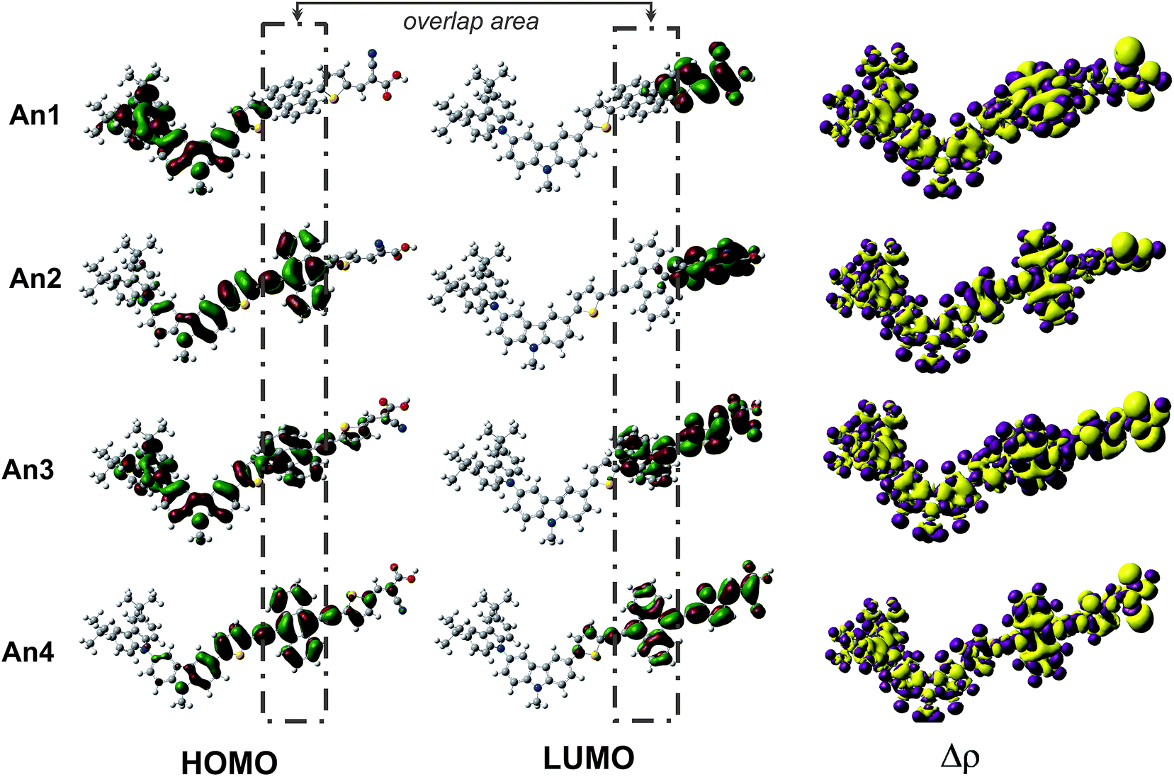 | ||
| Fig. 3 The frontier molecular orbitals of HOMO (left) and LUMO (middle), and the charge density difference between the ground- and excited-state (right) of the studied dyes calculated under TD-CAM-B3LYP/6-31G(d,p). The purple represent where the electrons are decreased and the yellow represents where the electrons are increased. | ||
Furthermore, we perform the Δρ plots revealing electron density differences between the ground- and excited-states to provide further evidence for ICT. The decreased (purple) mainly localized on the donor and linker parts, while the increased (yellow) electron densities localized on the anchoring group. In regards to the electron density delocalized throughout the entire molecular backbone, the ICT as well as the injection mechanism are possible when transition occurs for all dyes. The ICT property was generally accepted that is related to the dipole moment (μ) of the individual dye perpendicular to the surface of semiconductor. It is reasonable that the larger μ of the adsorbed dyes, the larger Voc. Therefore, we performed dipole moment calculation under B3LYP/6-31G(d,p) level at the geometry of isolated dyes. The calculated total dipole moments (μ) are listed in Table 2. The total μ of dyes increases in the order of An1 (6.30) < An2 (7.25) < An3 (7.47) < An4 (9.52) as the planarity changes. The largest vertical dipole moment of An4 dye is considered to provide the great ICT property.
| Dyes | μya (debye) | λabs, nm (eV) | f | LHEb | cE*ox | dΔGinject | Transition compositions |
|---|---|---|---|---|---|---|---|
| a μy is dipole moment in the direction perpendicular to the TiO2 surface.b LHE = 1−10−A = 1−10−f.c E*ox = Eox − λabs.d ΔGinject = E*ox − ECB. | |||||||
| An1 | 6.30 | 374 (3.31) | 0.8596 | 0.86 | 2.01 | −1.99 | (+0.62) H−1 → L+1, (−0.21) H−2 → L+1 |
| An2 | 7.25 | 450 (2.75) | 1.6038 | 0.97 | 2.39 | −1.61 | (+0.63) H → L+1, (+0.22) H−1 → L+1 |
| An3 | 7.47 | 490 (2.53) | 1.6325 | 0.98 | 2.71 | −1.29 | (+0.51) H−1 → L+1, (−0.40) H → L |
| An4 | 9.52 | 562 (2.21) | 2.2861 | 0.99 | 2.92 | −1.08 | (+0.63) H → L, (−0.17) H → L+1 |
3.3 Energy diagram
Fig. 4 shows calculated HOMO and LUMO energy levels for dyes An1–An4. Importantly, the HOMO energy level is required to match with the redox potential of the iodine/triiodide (I−/I3−) electrolyte system for suitable charge recombination back to the oxidized dyes, whereas the LUMO level is required to match with the TiO2 conduction band (CB) edge for efficient injection of excited electrons. For LUMO levels, the criterion for an efficient electron injection process requires that the energy gap between the LUMO and the CB edge of TiO2 is greater than approximately 0.2 eV.17 As shown in Fig. 4, the simulated LUMO levels are −2.89, −3.14, −2.96, and −3.12 eV for An1–An4 respectively, which are greater magnitude than the CB of (TiO2)38 cluster of −4.00 eV in the experiment. The energy gaps between the acceptor LUMO and TiO2 CB calculated to be 0.61, 0.36, 0.54, and 0.38 eV for the An1–An4 dyes, respectively, indicating that injection of excited electrons from the dye excited-state into the TiO2 conduction band edge should be thermodynamically favorable. | ||
| Fig. 4 Computed HOMO-LUMO energy levels for the studied dyes An1–An4 at the TD-CAM-B3LYP/6-31G(d,p), together with the TiO2 conduction band edge and the I−/I3− redox potential. | ||
For HOMO level, HOMO energy levels must lie below the I−/I3− redox couple (−4.80 eV)58,59 for efficient electron regeneration. Fig. 4 shows that the HOMO energies of the studied dyes are −5.31, −5.13, −5.23, and −5.14 eV for An1–An4, respectively. Thus, there is a sufficient driving force for fast and efficient regeneration of the oxidized dye. Relatively large energy gaps between the LUMO energies of these dyes and the semiconductor CB together with the low lying HOMO of the I−/I3− redox couple would be beneficial to photovoltaic conversion.
3.4 Absorption spectra and light harvesting properties
To determine the dye optical absorption characteristics and electronic transitions in CH2Cl2 solvent, we performed TD-DFT calculations using the CAM-B3LYP function under the C-PCM continuum salvation model. The calculated maximum absorption wavelengths (λabs), oscillator strengths (f), electronic transitions, and light harvesting efficiencies (LHE) are listed in Table 2. Simulated absorption spectra for the An1–An4 dyes are shown in Fig. 5. | ||
| Fig. 5 The calculated UV-Vis spectra of An1–An4 dyes using TD-CAM-B3LYP/6-31G(d,p) model in CH2Cl2 solution. | ||
The dyes exhibit two major absorption regions at roughly 292–374 and 450–562 nm. We ascribe the absorption bands below 400 nm to π–π* transitions of the conjugated molecules. Bands in the longer wavelength region greater than 400 nm commonly arise from to ICT transitions, which are an important band for DSSC applications. Fig. 5 shows that An1 exhibits λabs at 374 nm (Table S1†), which is below 400 nm, and thus ICT is probably absent due to the large dihedral angles measured at the position 9 and 10 of anthracene for An1, as discussed in Section 3.1.
It is interesting to compare the optical properties of the An1 dye without TB, and the An2–An4 dyes, which incorporate TB as a π linker. The dye λabs values fall in the order An4 (562 nm) > An3 (490 nm) > An2 (450 nm) > An1 (374 nm). The inclusion of TB in the π-conjugation chain causes red shift of the dye λabs values. Compared to λabs of An1 dye at 374 nm, the red shifts of the λabs are calculated to be 76, 116, and 188 nm for An2, An3, and An4, respectively. These results clearly indicate that TB significantly extends the π-conjugation length, resulting in emergence of strongly favorable ICT. The extension of the linker conjugation length is further confirmed by the L distance, which increases in the order An2 (8.18 Å) < An3 (10.72 Å) < An4 (17.53 Å). An4 exhibits the broadest and most intense absorption spectrum. Therefore, An4 is expected to be the most suitable dye for DSSC applications.
We also calculated light harvesting efficiency (LHE) to determine the extent of light absorption and Jsc values for the dyes.19 The LHE can be approximated by eqn (2).
| LHE = 1 − 10−A = 1 − 10−f | (2) |
| Jsc = ∫LHE(λ)Φinjectηcollectdλ | (3) |
 | ||
| Fig. 6 LHE curves of An1–An4 dyes along with photon flux spectrum at ASTM-G173 AM1.5 G. | ||
3.5 Driving force (ΔGinject) and the electron injection process
For electron injection processes in DSSCs, the free energy change (ΔGinject) is an important parameter for characterizing the rate and efficiency of the reaction. Fig. 7 shows the free energy change (ΔGinject) that occurs as a result of electron injection in a DSSC. The initial state of the reaction is the excited electron of dye adsorbed on a TiO2 surface, and the final state corresponds to the injected electron on TiO2 surface. The ΔGinject can be obtained from eqn (4), representing the energy difference between these initial and final states, where E*ox representing to the photo-induced excited states of the organic dyes and ECB representing to reduction potential of the TiO2 semiconductor. The E*ox can be computed from eqn (5), where Eox is the redox potential of the dye in the ground state and λabs is the absorption energy.| ΔGinject = E*ox − ECB | (4) |
| E*ox = Eox − λabs | (5) |
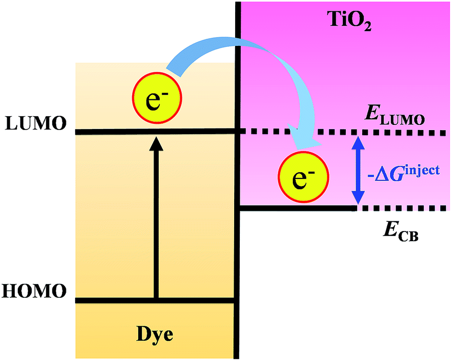 | ||
| Fig. 7 Schematic of free energy change (ΔGinject) producing form the energy difference between ELUMO and ECB. | ||
Taking into account the ΔGinject listed in Table 2, we found that all ΔGinject values are negative with sufficiently high ΔGinject value (>0.2 eV) to obtain a high efficiency of electron injection in DSSCs,60 the electron injection process thermodynamically possible (i.e., ΔGinject < 0), confirming that the LUMO level of the dye must lie above the TiO2 CB edge. Therefore, photo-excitation should be capable of producing sufficiently excited electrons for injection into the TiO2 conduction bands. To enable sufficient driving force for electron injection, a good overlap of the excited states of the dye and the potential of the TiO2 is crucial.61
To further study the structure of the dye sensitizer–semiconductor interface and the process of electron transfer from the dye sensitizer to semiconductor surface, we modeled the An1-, An2-, An3-, and An4–TiO2 adsorption complexes (Dyes–TiO2) using the DMol3 computer program. Fig. 8 shows the optimized structures, and Table 3 lists adsorption energies (Eads). As shown, the optimized adsorbed-dye structures are positioned almost perpendicular to the TiO2 surface, linked by two O–Ti bonds in a bidentate-bridging adsorption mode. The calculated Eads values for Dyes–TiO2 are in the range 19–21 kcal mol−1, indicating strong interactions between the dyes and the TiO2 surface. In addition, to consider dipole moment of the dyes adsorbed onto (TiO2)38 cluster, we made the C2 axis of the carboxylate in the dye parallel to the y-axis, and the semiconductor surface is parallel to the xz plane as shown in Fig. 8. The calculated dipole moments along y-axis (μy) of dyes increased in the order of An1 (21.730) < An2 (24.52) < An3 (25.04) < An4 (26.02), respectively. This calculated result confirms the strong intramolecular charge transfer (ICT) property of TB modified-linker dyes (An2, An3, An4) which expected to perform higher electron injection efficiency than An1 dye without TB.
 | ||
| Fig. 8 Optimized structures of An1-, An2-, An3- and An4–TiO2 adsorption complexes calculated by PBE/DNP in the DMol3. | ||
| Complexes | Eads (kcal mol−1) | Eex, eV (nm) | f | Transition compositions |
|---|---|---|---|---|
| a H = HOMO, H−1 = HOMO−1, H−2 = HOMO−2,…; L = LUMO, L+1 = LUMO+1, L+2 = LUMO+2,… | ||||
| An1–TiO2 | 20.72 | 3.07 (404) | 0.5570 | (+0.90) H → L |
| An2–TiO2 | 19.58 | 3.76 (449) | 1.6644 | (+0.24) H → L+60, (+0.24) H → L+59 |
| An3–TiO2 | 19.88 | 2.50 (495) | 2.0339 | (+0.26) H−1 → L+21, (+0.21) H−1 → L+12 |
| An4–TiO2 | 20.80 | 2.19 (566) | 2.6740 | (+0.26) H → L+9, (+0.26) H → L+20 |
Upon excitation, electronic coupling and electron transfer take place between the LUMO on the dye and the CB on TiO2. Thus, it is important to analyze the frontier molecular orbitals of the Dyes–TiO2 complexes, and for the LUMO in particular. To get more insights into the orbital charge densities for frontier molecular orbitals of the Dyes–TiO2 complexes, the optimized geometries of the Dyes–TiO2 complexes from DMol3 were further calculated the electronic transition energies with TD-DFT calculations using CAM-B3LYP functional with the 3-21G(d) basis as implemented in the GAUSSIAN 09 program. The results are shown in Table 3. Fig. 9 shows selected isosurface frontier molecular orbitals, including HOMO, LUMO, and other interacting orbitals of the Dyes–TiO2 complexes. For the An1–TiO2 adsorption complex (Fig. 9a), the electronic transition corresponds to a HOMO → LUMO interaction. The HOMO electron density localizes on the Cbz–Cbz donor group, while electron density in the LUMO is located on the TiO2 surface. However, this transition does not represent the direction of electron transfer, because there is no electron density located at the cyanoacrylic acid anchoring group for the LUMO of the dye acceptor. This calculated result probably arises because of the twisted anthracene geometry in An1, with dihedral angles at the 9- and 10-positions that are almost perpendicular to the cyanoacrylic acid anchoring plane, and which result in suppression of electron transfer.
 | ||
| Fig. 9 Electronic transitions of (a) An1–TiO2, (b) An2–TiO2, (c) An3–TiO2 and (d) An4–TiO2 adsorption complexes calculated by TD-CAM-B3LYP/3-21G(d). | ||
For the An2–TiO2 adsorption complex (Fig. 9b), the electronic transition corresponds to the linear combination of HOMO → LUMO+59 and HOMO → LUMO+60. The electron distribution of the HOMO mainly localizes on the anthracene moiety and the adjacent carbazole unit. This calculated result is consistent with the incorporation of TB between 9-anthracene and the carbazole donor, which results in a significantly decreased dihedral angle between anthracene and the adjacent carbazole group, and consequently improved electron transfer from the carbazole donor onto anthracene. However, electron density cannot extend past the 10-position because of the large dihedral angle, and consequently, there is no electron density located on the cyanoacrylic acid anchoring group for LUMO+59 or LUMO+60. Thus, this transition also could not represent a route for electron transfer from the dye to the TiO2 surface.
In contrast, An3–TiO2 and An4–TiO2 adsorption complexes (Fig. 9c and d) with TB at positions 10 and 9,10 on anthracene, respectively, have much smaller dihedral angles at the 10-position and are essentially planar. Consequently, electron transfer to the TiO2 surface via the cyanoacrylic-anchoring group can occur. On the other hand, in order to have back electron transfer, the electron from the TiO2 needs to enter the dye via the anchor. Therefore, if the LUMO of the dye is considerably more localized on the anchors and has a small contribution from the chromophoric unit, back electron transfer will be hampered.62 The charge recombination is found to be less probable in DMol3 program and An4 due to large contributions of the anchoring atoms to the LUMO orbital density compared to An1 and An2, see Fig. 9.
In order to understand electron injection mechanism we analyzed the energy level of the An3 and An4 dyes before and after interacting with the (TiO2)38 cluster (Fig. S1†), representing a schematic description of the electronic structure for the free dyes, bare TiO2 and dye@TiO2 system. We found that the LUMO level of the dye@TiO2 complex is lower than that for the free dye, which is above the CB level of the TiO2 indicating the efficient electron transfer from the dye to the semiconductor surface in DSCs. As shown, the HOMO−1 electron distribution for An3–TiO2 and HOMO for An4–TiO2 are mainly localized on the anthracene moiety, with slight delocalization to the anchoring group, while the patterns of LUMO+21 for An3–TiO2 and LUMO+20 for An4–TiO2, show that the electron distribution is delocalized across both the TiO2 surface and the cyanoacrylic-anchoring group. These distributions represent electron transfer from the dye via the anchoring group to the TiO2 surface as a consequence of direct electron injection. The effects of connecting the anchoring group to anthracene at different positions for An3–TiO2 (9-position) and An4–TiO2 (9,10-positions) adsorption complexes are similar. The reason is that electron density can transfer from anthracene to the TiO2 surface through the small dihedral angle between anthracene and thiophene at the 10-position. Thus, the presence of TB plays a key role in electron transfer and in the injection mechanism at the (TiO2)38 surface.
4. Conclusions
In summary, we used computational methods to design and investigate a series of three anthracene-based dyes, An2–An4, with a TB-modified π-conjugated linker and compared these to the An1 dye without TB substitution. Interestingly, all three anthracene-based sensitizers An2–An4 showed significant decreases in the dihedral angle between the anthracene unit and its substituents at the 9,10-positions, resulting in a nearly planar molecular geometry for each dye. The presence of a planar structure greatly affects the absorption spectra, which broadens with increasing coplanarity distance (L). Furthermore, molecular coplanarity of with the π-conjugated linker has a significant effect on electron distribution overlap on anthracene, which facilitates ICT. According to calculated absorption spectra, the An4 dye exhibits a prominent red-shift in its absorption peak, which is beneficial to its light-harvesting efficiency. The calculated electronic transitions for the dye–(TiO2)38 clusters revealed that dyes bearing a TB moiety directly linked between anthracene and the anchoring group, exhibit electron injection from the dye to the TiO2 surface. These results indicate that inclusion of a triple bond-modified π-conjugated linker in these dyes during synthesis is necessary for the construction of high-efficiency organic sensitizers.Acknowledgements
The authors acknowledge and thank the Department of Chemistry at Ubon Ratchathani and Chiang Mai Universities for providing access to their computing resources. Financial support from the Human Resource Development in Science Project (Science Achievement Scholarship of Thailand, SAST), Thailand Research Fund (grant number RSA5780048) and the Center of Excellence for Innovation in Chemistry (PERCH-CIC), the office of the Higher Education Commission, and the Ministry of Education are gratefully acknowledged.References
- B. O'Regan and M. Grätzel, Nature, 1991, 353, 737–740 CrossRef
.
- M. Grätzel, J. Photochem. Photobiol., C, 2003, 4, 145–153 CrossRef
- L. M. Peter, J. Phys. Chem. Lett., 2011, 2, 1861–1867 CrossRef CAS
- K. Srinivas, K. Yesudas, K. Bhanuprakash, V. J. Rao and L. Giribabu, J. Phys. Chem. C, 2009, 113, 20117–20126 CAS
- C. Teng, X. Yang, C. Yang, S. Li, M. Cheng, A. Hagfeldt and L. Sun, J. Phys. Chem. C, 2010, 114, 9101–9110 CAS
- J. Xu, L. Wang, G. Liang, Z. Bai, L. Wang, W. Xu and X. Shen, Spectrochim. Acta, Part A, 2011, 78, 287–293 CrossRef PubMed
- Z. Chen, F. Li and C. Huang, Curr. Org. Chem., 2007, 11, 1241–1258 CrossRef CAS
- M. Grätzel, Inorg. Chem., 2005, 44, 6841–6851 CrossRef PubMed
- H. Zhang, J. Fan, Z. Iqbal, D.-B. Kuang, L. Wang, D. Cao and H. Meier, Dyes Pigm., 2013, 99, 74–81 CrossRef CAS PubMed
- J. Zhang, H.-B. Li, Y. Geng, S.-Z. Wen, R.-L. Zhong, Y. Wu, Q. Fu and Z.-M. Su, Dyes Pigm., 2013, 99, 127–135 CrossRef CAS PubMed
- L.-L. Tan, L.-J. Xie, Y. Shen, J.-M. Liu, L.-M. Xiao, D.-B. Kuang and C.-Y. Su, Dyes Pigm., 2014, 100, 269–277 CrossRef CAS PubMed
- A. Yella, R. Humphry-Baker, B. F. E. Curchod, N. Ashari Astani, J. Teuscher, L. E. Polander, S. Mathew, J.-E. Moser, I. Tavernelli, U. Rothlisberger, M. Grätzel, M. K. Nazeeruddin and J. Frey, Chem. Mater., 2013, 25, 2733–2739 CrossRef CAS
- H. Tian, X. Yang, R. Chen, Y. Pan, L. Li, A. Hagfeldt and L. Sun, Chem. Commun., 2007, 3741–3743 RSC
- C.-J. Yang, Y. J. Chang, M. Watanabe, Y.-S. Hon and T. J. Chow, J. Mater. Chem., 2012, 22, 4040–4049 RSC
- L. Ducasse, F. Castet, R. Méreau, S. Nénon, J. Idé, T. Toupance and C. Olivier, Chem. Phys. Lett., 2013, 556, 151–157 CrossRef CAS PubMed
- A. S. Hart, C. B. Kc, H. B. Gobeze, L. R. Sequeira and F. D'Souza, ACS Appl. Mater. Interfaces, 2013, 5, 5314–5323 CAS
- H. W. Ham and Y. S. Kim, Thin Solid Films, 2010, 518, 6558–6563 CrossRef CAS PubMed
- J. Zhang, Y.-H. Kan, H.-B. Li, Y. Geng, Y. Wu and Z.-M. Su, Dyes Pigm., 2012, 95, 313–321 CrossRef CAS PubMed
- W. Fan, D. Tan and W.-Q. Deng, ChemPhysChem, 2012, 13, 2051–2060 CrossRef CAS PubMed
- C.-Y. Lin, Y.-C. Wang, S.-J. Hsu, C.-F. Lo and E. W.-G. Diau, J. Phys. Chem. C, 2009, 114, 687–693 Search PubMed
- Y.-S. Yen, Y.-C. Chen, H.-H. Chou, S.-T. Huang and J. T. Lin, Polymers, 2012, 4, 1443–1461 CrossRef PubMed
- R. Yeh-Yung Lin, H.-W. Lin, Y.-S. Yen, C.-H. Chang, H.-H. Chou, P.-W. Chen, C.-Y. Hsu, Y.-C. Chen, J. T. Lin and K.-C. Ho, Energy Environ. Sci., 2013, 6, 2477–2486 CAS
- Y.-Z. Lin, C. H. Huang, Y. J. Chang, C.-W. Yeh, T.-M. Chin, K.-M. Chi, P.-T. Chou, M. Watanabe and T. J. Chow, Tetrahedron, 2014, 70, 262–269 CrossRef CAS PubMed
- J. Yang, F. Guo, J. Hua, X. Li, W. Wu, Y. Qu and H. Tian, J. Mater. Chem., 2012, 22, 24356–24365 RSC
- S. J. Kim, D. U. Heo, B. J. Yoo, B. Kim, M. J. Ko, M. J. Cho and D. H. Choi, Bull. Korean Chem. Soc., 2013, 34, 1081–1088 CrossRef
- A. Hagfeldt, G. Boschloo, L. Sun, L. Kloo and H. Pettersson, Chem. Rev., 2010, 110, 6595–6663 CrossRef CAS PubMed
- K. R. Justin Thomas, P. Singh, A. Baheti, Y.-C. Hsu, K.-C. Ho and J. T. s. Lin, Dyes Pigm., 2011, 91, 33–43 CrossRef PubMed
- H. Li, Y. Yang, Y. Hou, R. Tang, T. Duan, J. Chen, H. Wang, H. Han, T. Peng, X. Chen, Q. Li and Z. Li, ACS Sustainable Chem. Eng., 2014, 2, 1776–1784 CrossRef CAS
- C. Yan, W. Ma, Y. Ren, M. Zhang and P. Wang, ACS Appl. Mater. Interfaces, 2015, 7, 801–809 CAS
- L. Yang, Y. Ren, Z. Yao, C. Yan, W. Ma and P. Wang, J. Phys. Chem. C, 2015, 119, 980–988 CAS
- C.-K. Tai, Y.-J. Chen, H.-W. Chang, P.-L. Yeh and B.-C. Wang, Comput. Theor. Chem., 2011, 971, 42–50 CrossRef CAS PubMed
- Z. Cai-Rong, L. Zi-Jiang, C. Yu-Hong, C. Hong-Shan, W. You-Zhi and Y. Li-Hua, J. Mol. Struct.: THEOCHEM, 2009, 899, 86–93 CrossRef PubMed
- C.-R. Zhang, L. Liu, Z.-J. Liu, Y.-L. Shen, Y.-T. Sun, Y.-Z. Wu, Y.-H. Chen, L.-H. Yuan, W. Wang and H.-S. Chen, J. Mol. Graphics Modell., 2012, 38, 419–429 CrossRef CAS PubMed
- S.-L. Chen, L.-N. Yang and Z.-S. Li, J. Power Sources, 2013, 223, 86–93 CrossRef CAS PubMed
- A. Irfan, Mater. Chem. Phys., 2013, 142, 238–247 CrossRef CAS PubMed
- F. Labat, T. Le Bahers, I. Ciofini and C. Adamo, Acc. Chem. Res., 2012, 45, 1268–1277 CrossRef CAS PubMed
- S. Jungsuttiwong, T. Yakhanthip, Y. Surakhot, J. Khunchalee, T. Sudyoadsuk, V. Promarak, N. Kungwan and S. Namuangruk, J. Comput. Chem., 2012, 33, 1517–1523 CrossRef CAS PubMed
- T. Yakhanthip, S. Jungsuttiwong, S. Namuangruk, N. Kungwan, V. Promarak, T. Sudyoadsuk and P. Kochpradist, J. Comput. Chem., 2011, 32, 1568–1576 CrossRef CAS PubMed
- S. Namuangruk, R. Fukuda, M. Ehara, J. Meeprasert, T. Khanasa, S. Morada, T. Kaewin, S. Jungsuttiwong, T. Sudyoadsuk and V. Promarak, J. Phys. Chem. C, 2012, 116, 25653–25663 CAS
- R. Tarsang, V. Promarak, T. Sudyoadsuk, S. Namuangruk and S. Jungsuttiwong, J. Photochem. Photobiol., A, 2014, 273, 8–16 CrossRef CAS PubMed
- N. Kungwan, P. Khongpracha, S. Namuangruk, J. Meeprasert, C. Chitpakdee, S. Jungsuttiwong and V. Promarak, Theor. Chem. Acc., 2014, 133, 1–14 Search PubMed
- M. J. Frisch, G. W. Trucks, H. B. Schlegel, G. E. Scuseria, M. A. Robb, J. R. Cheeseman, G. Scalmani, V. Barone, B. Mennucci, G. A. Petersson, H. Nakatsuji, M. Caricato, X. Li, H. P. Hratchian, A. F. Izmaylov, J. Bloino, G. Zheng, J. L. Sonnenberg, M. Hada, M. Ehara, K. Toyota, R. Fukuda, J. Hasegawa, M. Ishida, T. Nakajima, Y. Honda, O. Kitao, H. Nakai, T. Vreven, J. A. Montgomery Jr, J. E. Peralta, F. Ogliaro, M. Bearpark, J. J. Heyd, E. Brothers, K. N. Kudin, V. N. Staroverov, R. Kobayashi, J. Normand, K. Raghavachari, A. Rendell, J. C. Burant, S. S. Iyengar, J. Tomasi, M. Cossi, N. Rega, J. M. Millam, M. Klene, J. E. Knox, J. B. Cross, V. Bakken, C. Adamo, J. Jaramillo, R. Gomperts, R. E. Stratmann, O. Yazyev, A. J. Austin, R. Cammi, C. Pomelli, J. W. Ochterski, R. L. Martin, K. Morokuma, V. G. Zakrzewski, G. A. Voth, P. Salvador, J. J. Dannenberg, S. Dapprich, A. D. Daniels, Ö. Farkas, J. B. Foresman, J. V. Ortiz, J. Cioslowski and D. J. Fox, Gaussian 09, Revision C.01, Gaussian, Inc., Wallingford CT, 2009 Search PubMed
- A. D. Becke, J. Chem. Phys., 1993, 98, 1372–1377 CrossRef CAS PubMed
- G. A. Petersson, A. Bennett, T. G. Tensfeldt, M. A. Al-Laham, W. A. Shirley and J. Mantzaris, J. Chem. Phys., 1988, 89, 2193–2218 CrossRef CAS PubMed
- M. Pastore, E. Mosconi, F. De Angelis and M. Grätzel, J. Phys. Chem. C, 2010, 114, 7205–7212 CAS
- S. I. Gorelsky and A. B. P. Lever, J. Organomet. Chem., 2001, 635, 187–196 CrossRef CAS
- M. K. Nazeeruddin, F. De Angelis, S. Fantacci, A. Selloni, G. Viscardi, P. Liska, S. Ito, B. Takeru and M. Grätzel, J. Am. Chem. Soc., 2005, 127, 16835–16847 CrossRef CAS PubMed
- B. Delley and D. E. Ellis, J. Chem. Phys., 1982, 76, 1949–1960 CrossRef CAS PubMed
- S. Namuangruk, K. Sirithip, R. Rattanatwan, T. Keawin, N. Kungwan, T. Sudyodsuk, V. Promarak, Y. Surakhot and S. Jungsuttiwong, Dalton Trans., 2014, 9166–9176 RSC
- S. Namuangruk, J. Meeprasert, S. Jungsuttiwong, V. Promarak and N. Kungwan, Theor. Chem. Acc., 2014, 133, 1–15 CrossRef CAS PubMed
- R. Tarsang, V. Promarak, T. Sudyoadsuk, S. Namuangruk, N. Kungwan and S. Jungsuttiwong, ChemPhysChem, 2014, 15, 3809–3818 CrossRef CAS PubMed
- S. Jungsuttiwong, R. Tarsang, T. Sudyoadsuk, V. Promarak, P. Khongpracha and S. Namuangruk, Org. Electron., 2013, 14, 711–722 CrossRef CAS PubMed
- E. Ronca, M. Pastore, L. Belpassi, F. Tarantelli and F. De Angelis, Energy Environ. Sci., 2013, 6, 183–193 CAS
- M. Khoudiakov, A. R. Parise and B. S. Brunschwig, J. Am. Chem. Soc., 2003, 125, 4637–4642 CrossRef CAS PubMed
- Y.-X. Weng, Y.-Q. Wang, J. B. Asbury, H. N. Ghosh and T. Lian, J. Phys. Chem. B, 2000, 104, 93–104 CrossRef CAS
- F. D. Angelis, S. Fantacci and A. Selloni, Nanotechnology, 2008, 19, 424002 CrossRef PubMed
- F. De Angelis, S. Fantacci, E. Mosconi, M. K. Nazeeruddin and M. Grätzel, J. Phys. Chem. C, 2011, 115, 8825–8831 CAS
- D. Cahen, G. Hodes, M. Grätzel, J. F. Guillemoles and I. Riess, J. Phys. Chem. B, 2000, 104, 2053–2059 CrossRef CAS
- W. Sang-aroon, S. Saekow and V. Amornkitbamrung, J. Photochem. Photobiol., A, 2012, 236, 35–40 CrossRef CAS PubMed
- R. Katoh and A. Furube, J. Photochem. Photobiol., C, 2014, 20, 1–16 CrossRef CAS PubMed
- J. Wiberg, T. Marinado, D. P. Hagberg, L. Sun, A. Hagfeldt and B. Albinsson, J. Phys. Chem. B, 2010, 114, 14358–14363 CrossRef CAS PubMed
- S. M. Pratik and A. Datta, Phys. Chem. Chem. Phys., 2013, 15, 18471–18481 RSC
Footnote |
| † Electronic supplementary information (ESI) available. See DOI: 10.1039/c5ra04408a |
| This journal is © The Royal Society of Chemistry 2015 |