DOI:
10.1039/C5RA03297K
(Paper)
RSC Adv., 2015,
5, 44873-44885
Ultrasonic, spectrophotometric and theoretical studies of sigma and PI interactions of iodine with substituted benzene†
Received
22nd February 2015
, Accepted 29th April 2015
First published on 29th April 2015
Abstract
The charge transfer (CT) interaction between three structurally different benzenoid compounds (donors), namely, chlorobenzene (1), phenol (2), anisole (3), and iodine (I2, acceptor) were investigated by experimental methods (ultrasonic and UV-Visible analysis) and theoretical calculations. Notably, strong solute–solute interactions and the existence of a CT type of interaction between 1–3 and I2 is clearly analyzed from the trend in acoustical and excess thermo acoustical parameters with concentration at 303 K in an n-hexane medium. The formation of 1![[thin space (1/6-em)]](https://www.rsc.org/images/entities/char_2009.gif) :1 complexes between iodine and 1–3 was established by the UV-visible spectroscopic method. The structure and stabilization energies of 1–3 and I2 were further calculated by DFT calculations. Among the σ- and π-type interactions, a π-type complex (1a–3a) with an atom-centered orientation is found to be the preferred and stable geometry for all the CT complexes. The stability constant of the CT complexes was calculated by spectroscopic and ultrasonic methods, which show a similar trend with the DFT computed stabilization energies. Furthermore, AIM and NBO analyses were used to quantify the nature of the stabilizing interactions that exist in 1–3 and the I2 CT complexes. Our computed results are in good agreement with the experimental observations.
:1 complexes between iodine and 1–3 was established by the UV-visible spectroscopic method. The structure and stabilization energies of 1–3 and I2 were further calculated by DFT calculations. Among the σ- and π-type interactions, a π-type complex (1a–3a) with an atom-centered orientation is found to be the preferred and stable geometry for all the CT complexes. The stability constant of the CT complexes was calculated by spectroscopic and ultrasonic methods, which show a similar trend with the DFT computed stabilization energies. Furthermore, AIM and NBO analyses were used to quantify the nature of the stabilizing interactions that exist in 1–3 and the I2 CT complexes. Our computed results are in good agreement with the experimental observations.
1 Introduction
The directional non-covalent interactions between donors and acceptors such as halogens are inevitable in the context of frontier research areas, which include crystal engineering, drug design, and protein–ligand complexation.1–3 These complexes have been identified as potential candidates for non-linear optical materials and electrical conductivity.4 In 1863, Guthrie and coworkers first reported the charge transfer (CT) complexes between ammonia and iodine (NH3⋯I2) systems.5 Charge–transfer interactions (CT) are a special type of non-covalent interaction, which are ubiquitous in nature and are of great importance in many biological processes. Over the years, benzene–I2 systems have been considered as a classical case of CT type interactions. Later, Hildebrand6 reported the absorption characteristics of benzene–iodine CT complexes. Furthermore, the formation of CT complexes was investigated by Mülliken who used the resonance model through spectroscopic and dipole moment studies.7,8 Subsequently, a significant number of reports on spectroscopic and theoretical studies revealed the geometry of CT complexes between benzene and electrophilic halogens.9–11 Notably, Fredin12,13 and Ferguson14,15 suggested the existence of the axial structure of benzene–iodine CT complexes in a nitrogen matrix through IR experiments.
In conjunction with experimental measurements, electronic structure calculations16,17 have been performed over the years to determine the most stable geometry conformation of benzene–iodine CT complexes. Both the density functional theory (DFT) based calculations (commonly the B3LYP functional is used) and “ab initio CCSD(T)” calculations by Mebel et al.18 pointed out that the most stable geometry for benzene–iodine CT complexes is the above-bond conformation and not the axial type. Moreover, a photo dissociation dynamics study of benzene–iodine complexes in a benzene solution using CT band resonance Raman spectra combined with DFT calculations showed that the atom-center-oriented geometry was found to be the active geometry in their CT excitation states.19 In addition, the combined UV-PES and ab initio molecular orbital studies of Venuvanalingam and coworkers clearly explained the possibility of the existence of the most stable bond centered oblique structure of benzene–iodine monochloride (ICl) CT complexes.20
Ultrasonic investigations of binary and ternary liquid mixtures are convenient and non-destructive methods and have much significance in assessing the nature of molecular interactions in liquid mixtures.21–24 However, in recent years, the acoustical investigations have been successfully employed in the detection and determination of the stability constants and thermodynamic properties of several CT and hydrogen bonded complexes.25–28 Spectroscopic techniques have been employed extensively by several authors to determine the equilibrium constant and extinction co-efficient (ε) of CT complexes. The effect of substituents on the aromatic moiety on the stability of these complexes has been studied using IR, NMR and UV-visible spectral techniques.29,30 The formation of CT complexes between iodine, as a σ-acceptor, and certain heterocyclic compounds has been investigated using ultrasonic and UV-visible spectral methods in a DMSO medium by Ulagendran et al.31 They found that both UV-visible and ultrasonic methods yielded similar association constant values for CT complexes.
Iodine is a good example as an acceptor species among the halogens for CT interactions with electron rich benzenoid compounds and it has biological applications.32 In order to understand the stability and orientational aspects of CT complexes of I2 with benzenoid compounds, three systems have been chosen. The understanding of the orientation of electrophilic iodine on the aromatic ring with respect to different substituents is comprehensively addressed from the experimental and theoretical viewpoints by considering the phenol⋯I2, anisole⋯I2 and chlorobenzene⋯I2 systems. The notable feature of our study is the application of ultrasonic scanning in the ternary systems for the detection of CT complexes and determination of their stability constants. Thermo-acoustic and excess thermo-acoustical properties are reported to be in support with the formation of these complexes. Often in the acoustical method, the Marwein–Bhatt equation33 is used to calculate the stability constants. However, this method is suitable for relatively strong CT complexes; moreover, the formation constants obtained by this method is concentration dependent. In the present study, Kannappan equation31b was utilized to determine the concentration independent stability constant and thermodynamic properties of weak complexes. Spectral and theoretical methods are used as supportive methods. Interestingly, our present study comprehensively compares the structural, stability, bonding and spectral aspects of classical and halogen bonded complexes of chlorobenzene, phenol and anisole with iodine using the acoustic method along with UV-Visible and theoretical methods (AIM, NBO & TDDFT).
2 Materials and methods
MERCK AR grade iodine, chlorobenzene (1), phenol (2), anisole (3) and n-hexane were purchased from S D fine chemicals, India. Iodine was purified by sublimation and 1–3 were distilled before use in order to achieve higher purity. The density, (ρ), of the pure liquids and their ternary systems were determined accurately using a 10 mL specific gravity bottle. Ultrasonic velocities in pure liquids and their ternary liquid mixtures were measured with an accuracy of 0.1 m s−1 using a single crystal variable path ultrasonic interferometer operating at 2 MHz frequency. Viscosity measurements were made with an Ostwald's viscometer in which the flow time of solutions was measured using a digital stop clock of accuracy ±0.01 s. The temperature of the samples was maintained at 303 K using a digitally controlled thermostatic water bath. Electronic absorption spectra of the samples were recorded on a PERKIN ELMER LAMDA 25 model spectrophotometer, which was provided with thermostatic control at 303 K. The stability constants of the CT complexes of 1–3 with iodine were determined from the slope and intercept of Benesi–Hildebrand (B–H) plots.
2.1 Method of calculation for acoustical parameters
Various acoustical and excess thermo acoustical parameters were calculated from the measured values of ultrasonic velocity (u), density (ρ) and viscosity (η) using the standard formulae.24,31b Isentropic compressibility (κs) can be calculated from ultrasound speed and density for a given solution at a given temperature using eqn (1):
The following eqn (2)–(4) are used to calculate free length (Lf), internal pressure (πi), and specific acoustic impedance (Z):
KT is a temperature dependent constant. Its value is (93.875 + 0.375 T) × 10−8
| | |
πi = bRT(Kη/u)1/2ρ2/3/Meff
| (3) |
In the abovementioned equations, effective molecular weight is calculated from the mole fraction (xi) and molecular weight (Mi) of the pure component ‘i’ using the equation  and b is a constant. Its value is 2; R is the universal gas constant; K is a temperature independent constant, which is equal to 4.28 × 10⁹ for all liquids, u is ultrasonic velocity and ρ is the measured density.
The excess thermoacoustic parameter is defined as the difference between the experimental and ideal mixture values. It is a measure of the non-ideal behaviour of a system as a consequence of associative or other interactions. The excess thermo acoustic property (YE) is obtained using the following general equation:
| |
 | (5) |
where
Y is the experimental thermo acoustic property;
xi is the mole fraction of the
ith component and
yi is the thermo acoustic property of the pure component
i.
Marwein and Bhatt33 proposed an equation to calculate the stability constants of donor–acceptor complexes in binary liquids. Their equation generally gives a concentration dependent formation constant and it can be used only for relatively stable and strong complexes. Recently, Kannappan et al.31b proposed an equation to calculate the formation constant values of charge transfer complexes, which is appreciable especially to weak complexes and in very dilute solutions. The equilibrium constant for a 1:1 stoichiometric reaction is calculated from the ultrasonic velocity using the Kannappan equation41 as follows:
here,
| y = (a − k1/2b)/(k − k1/2) |
where
k =
x/
y,
x is the difference between
ucal and
uobs at lower concentration ‘
a’,
y is the difference between
ucal and
uobs at higher concentration ‘
b’ and
ucal is the ultrasonic velocity of the mixture calculated from the mole fraction of the components using the additive principle.
2.2 Computational details
Quantum chemical calculations were carried out using the Gaussian 09 (ref. 34) and Orca 3.0 (ref. 35) programs. The CT complexes were optimized at the BP86 (ref. 36 and 37) functional level in combination with Grimme's D3 dispersion correction38 using def2-TZVP for carbon and hydrogen and segmented all electron relativistically contracted (SARC) for the iodine atom. Followed by structural optimization, vibrational frequencies were computed to confirm the stationary points as well as to identify the unrealistic saddle points. Relativistic effects are incorporated using ZORA. B3LYP39 with the def2-TZVP basis set (for iodine, all electrons scalar relativistic basis set (SARC)40) used to carry out the single point energy calculation. All interaction energy calculations were corrected for the basis set superposition error (BSSE) utilizing counterpoise correction.41 We found that the computed BSSE (using BP86/def2-TZVP) is less than 3 kJ mol−1, hence the total binding affinity is unaltered. Thus, the computed binding free energies are BSSE uncorrected. In addition to the gas phase calculations, the influence of solvent on the CT complex formation was considered by carrying out the conductor like screening model (COSMO)42 method in n-hexane (ε = 1.89). Time dependent density functional theory (TDDFT43) and natural bond orbital analysis (NBO44,45) calculations were carried out using G09. Herein, ω-B97X-D3 (ref. 46) with the 6-311++G(d,p) basis set for other atoms and SDB-aug-cc-pVQZ47a basis set for the iodine atom was used to carry out the NBO analysis and TD-DFT calculations. Solvent effects on the absorption spectra were evaluated on the gas phase optimized geometries with n-hexane, using the SCRF-PCM method.47b–d First 20 roots were considered in the TD-DFT calculations. Bader's topological analysis was performed using the AIM2000 software.48 The B3LYP/6-311++g(d,p) level was used to generate the necessary wave functions for the topological analysis.
3 Results and discussion
3.1 Acoustical analysis
The ultrasonic velocity (u), density (ρ) and viscosity (η) for the ternary systems (1–3) are summarized in Table 1. The plot of ultrasonic velocity (u) against concentration for 1–3 is presented in Fig. 1. It is clear from the plots in Fig. 1(a) and the data in Table 1 that ultrasonic velocity increases with the increasing concentration of components in all three ternary systems. It is observed that the increase is not perfectly linear with concentration in the three systems. The similar type of variation in ‘u’ in 1 to 3 suggests the existence of the same type of interaction in all three systems. The solute–solvent interaction in these ternary systems is less prominent since the chemically inert and non-polar n-hexane is employed. Hence, the increase in ultrasonic velocity with increasing the concentration is largely associated with the solute–solute interaction of unlike molecules.49 It is well known that phenol is an associated liquid and the association occurs through strong intermolecular hydrogen bonds.50 The increase in ‘u’ is steeper above 0.004 M and this suggests that there is a rupture of hydrogen bonding of like molecules at this concentration, and above this concentration, the specific interaction between the unlike molecules appears to be dominant. A similar trend is also observed for the variation of density in 2.
Table 1 Measured values of ultrasonic velocity (u), density (ρ) and coefficient of viscosity (η) for the ternary systems 1 to 3 with iodine in n-hexane at 303 K
| C (mol dm−3) |
Chlorobenzene–I2 |
Phenol–I2 |
Anisole–I2 |
| u (m s−1) |
ρ (kg m−3) |
η × 10−4 (N s m−2) |
u (m s−1) |
ρ (kg m−3) |
η × 10−4 (N s m−2) |
u (ms−1) |
ρ (kg m−3) |
η × 10−4 (N s m−2) |
| 0.002 |
1066.6 |
645.6 |
4.81 |
1064.5 |
655.2 |
4.17 |
1066.2 |
653.6 |
3.80 |
| 0.004 |
1067.5 |
646.3 |
4.83 |
1065.1 |
657.1 |
4.22 |
1067.1 |
654.0 |
4.02 |
| 0.006 |
1068.2 |
648.0 |
4.83 |
1066.3 |
658.1 |
4.24 |
1067.4 |
655.0 |
4.02 |
| 0.008 |
1068.6 |
648.8 |
4.84 |
1066.8 |
660.6 |
4.24 |
1068.1 |
655.7 |
4.03 |
| 0.01 |
1069.6 |
651.5 |
4.84 |
1067.5 |
663.6 |
4.27 |
1068.4 |
656.0 |
4.04 |
| 0.012 |
1070.3 |
652.6 |
4.86 |
1068.4 |
665.0 |
4.30 |
1069.2 |
657.4 |
4.05 |
| 0.014 |
1071.4 |
653.3 |
4.86 |
1069.8 |
666.8 |
4.31 |
1070.6 |
658.5 |
4.05 |
| 0.016 |
1072.7 |
656.7 |
4.87 |
1070.8 |
667.9 |
4.33 |
1071.7 |
658.7 |
4.09 |
| 0.018 |
1074.0 |
656.9 |
4.88 |
1071.8 |
668.3 |
4.35 |
1072.3 |
659.3 |
4.10 |
| 0.020 |
1075.6 |
658.2 |
4.89 |
1072.4 |
668.8 |
4.66 |
1073.4 |
660.2 |
4.16 |
 |
| | Fig. 1 Plots of (a) ultrasonic velocity versus concentration, (b) isentropic compressibility versus concentration for the three ternary systems of 1–3 with iodine in n-hexane at 303 K. | |
Plots of isentropic compressibility vs. concentration are given in Fig. 1(b). Isentropic compressibility, κs, is found to decrease with the increasing concentration in 1–3, which is the reverse trend as that of ultrasonic velocity (Table 2). The decrease in isentropic compressibility (κs) in liquid mixtures indicates that there is a definite contraction on mixing, and the considerable variation is attributed to strong interactions such as complex formation involving CT complexes.51 Compressibility changes with structure leads to the change in ultrasonic velocity. It is seen that the decrease in κs is significant in 2 above 0.006 M and this also shows that the structure breaking behaviour in 2 is dominant in very dilute solutions (<0.006 M) and the non-covalent CT complex formation is dominant above this concentration. The variation of ultrasonic velocity (u) is predominately determined by another important acoustical parameter, which is the intermolecular free length (Lf). The intermolecular free length (Lf) reflects similar behaviour as isentropic compressibility (κs) in such a way that there is a regular decrease in Lf with an increase in concentration in all the three systems. The decrease in compressibility brings the molecules to close packing, which results in the decrease of intermolecular free length. The decrease in intermolecular free length leads to a positive deviation in sound velocity and negative deviation in compressibility. Lf values are computed for 1–3 at 300 K and are listed in Table 2. It is observed that there is decrease in the Lf value with concentration in the three systems. This clearly indicates the closer proximity of the unlike molecules in the ternary systems. Furthermore, the trend in Lf value with concentration is similar to the trend in κs values in the three systems. It is interesting to note that the Lf value in 2 increases in very dilute solutions and then decreases with an increase in concentration as in the other two systems. This suggests that there is structure breaking of the associated phenol by solvent molecules and then only complex formation occurs.21,52 The combination of structure breaking behaviour and charge transfer complex formation between I2 and 2 is clearly supported by strong solute–solute interactions in the ternary mixtures. This is also supported by the internal pressure (πi) values (Table 2). In 2, the πi value is slightly higher in very dilute solutions, decreases up to 0.006 M and thereafter remains constant. This suggests that the structure breaking property is dominant up to the concentration of 0.006 M. Above this concentration complex formation is significant.53 This type of behaviour is not obtained in the case of 1 and 3. At the same concentration, Lf remains constant in the case of 1 and 3. It may be pointed out that above the 0.006 M concentration, the πi values are in the following order: 3 > 2 > 1. This trend clearly suggests that CT complex formation is significant above this concentration.
Table 2 The values of isentropic compressibility (κ), free length (Lf), internal pressure (πi) and acoustic impedance (Z) along with their excess values including velocity (uE) for the ternary systems 1 to 3 with iodine in n-hexane at 303 K
| C mol dm−3 |
κ × 10−9 (kg−1 ms−2) |
Lf × 10−11 (m) |
πi × 105 (atm) |
Z × 105 (kg m−2 s−1) |
Excess acoustical parameters |
| κE × 10−9 (pa−1) |
LEf × 10−11 (Å) |
ZE × 103 (kg m−2 s−1) |
uE (m s−1) |
| Chlorobenzene–I2 |
| 0.002 |
1.361 |
7.379 |
2.884 |
6.885 |
−0.318 |
0.066 |
−1.433 |
2.0 |
| 0.004 |
1.357 |
7.369 |
2.889 |
6.899 |
−0.656 |
0.062 |
−1.930 |
2.8 |
| 0.006 |
1.352 |
7.355 |
2.891 |
6.921 |
−1.120 |
0.061 |
−1.613 |
3.3 |
| 0.008 |
1.349 |
7.347 |
2.894 |
6.933 |
−1.342 |
0.060 |
−2.349 |
3.6 |
| 0.01 |
1.341 |
7.325 |
2.899 |
6.968 |
−2.090 |
0.057 |
−0.741 |
4.4 |
| 0.012 |
1.337 |
7.314 |
2.905 |
6.984 |
−2.440 |
0.056 |
−0.962 |
5.0 |
| 0.014 |
1.333 |
7.303 |
2.904 |
6.999 |
−2.802 |
0.055 |
−1.355 |
6.0 |
| 0.016 |
1.323 |
7.275 |
2.913 |
7.044 |
−3.763 |
0.052 |
1.240 |
7.1 |
| 0.018 |
1.319 |
7.265 |
2.913 |
7.055 |
−4.066 |
0.051 |
0.437 |
8.3 |
| 0.020 |
1.313 |
7.247 |
2.915 |
7.080 |
−4.677 |
0.049 |
1.040 |
9.7 |
| |
| Phenol–I2 |
| 0.002 |
1.346 |
7.339 |
2.715 |
6.975 |
−1.793 |
−4.799 |
7.440 |
−0.1 |
| 0.004 |
1.341 |
7.324 |
2.734 |
6.999 |
−2.277 |
−6.048 |
7.912 |
0.3 |
| 0.006 |
1.336 |
7.311 |
2.740 |
7.017 |
−2.719 |
−7.185 |
7.778 |
1.3 |
| 0.008 |
1.330 |
7.294 |
2.744 |
7.047 |
−3.279 |
−8.650 |
8.772 |
1.6 |
| 0.01 |
1.322 |
7.272 |
2.760 |
7.084 |
−4.023 |
−10.62 |
10.59 |
2.1 |
| 0.012 |
1.317 |
7.258 |
2.771 |
7.105 |
−4.451 |
−11.73 |
10.71 |
2.7 |
| 0.014 |
1.310 |
7.239 |
2.775 |
7.133 |
−5.090 |
−13.42 |
11.65 |
3.9 |
| 0.016 |
1.305 |
7.227 |
2.782 |
7.151 |
−5.481 |
−14.44 |
11.45 |
4.7 |
| 0.018 |
1.302 |
7.217 |
2.786 |
7.163 |
−5.755 |
−15.13 |
10.69 |
5.5 |
| 0.020 |
1.300 |
7.211 |
2.883 |
7.172 |
−5.942 |
−15.58 |
9.664 |
5.9 |
| |
| Anisole–I2 |
| 0.002 |
1.345 |
7.336 |
2.586 |
6.969 |
−1.907 |
−5.111 |
6.877 |
1.7 |
| 0.004 |
1.342 |
7.328 |
2.658 |
6.979 |
−2.136 |
−5.668 |
5.892 |
2.3 |
| 0.006 |
1.339 |
7.320 |
2.658 |
6.992 |
−2.369 |
−6.236 |
5.280 |
2.4 |
| 0.008 |
1.336 |
7.311 |
2.661 |
7.004 |
−2.639 |
−6.905 |
4.556 |
3.0 |
| 0.01 |
1.335 |
7.308 |
2.662 |
7.008 |
−2.695 |
−6.989 |
3.060 |
3.0 |
| 0.012 |
1.330 |
7.294 |
2.667 |
7.029 |
−3.142 |
−8.149 |
3.276 |
3.7 |
| 0.014 |
1.324 |
7.279 |
2.666 |
7.05 |
−3.645 |
−9.462 |
3.430 |
4.9 |
| 0.016 |
1.321 |
7.270 |
2.677 |
7.059 |
−3.905 |
−10.10 |
2.403 |
5.8 |
| 0.018 |
1.319 |
7.263 |
2.679 |
7.069 |
−4.100 |
−10.57 |
1.493 |
6.2 |
| 0.020 |
1.314 |
7.251 |
2.698 |
7.086 |
−4.497 |
−11.60 |
1.249 |
7.1 |
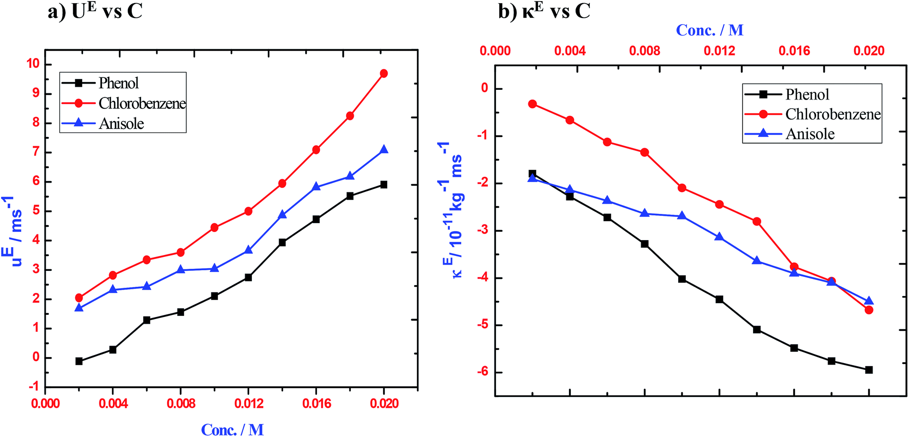
In order to confirm the existence of non-covalent interactions between the donor and acceptor, the excess values of the acoustical parameters, such as κs, Lf and acoustic impedance (Z), were calculated. The sign and magnitude of excess ultrasound speed (uE) play a prominent role in describing the molecular interactions that occur among the molecules of the components in liquid mixtures. Any non-zero value in the excess parameter is a measure of non-linearity and is indicative of the existence of strong non-covalent interactions among the components of the systems.25,26 The negative value of excess adiabatic compressibility indicates that strong attractive interactions are likely to occur between the components, while for mixtures with only weak London type interactions possess a positive value of excess adiabatic compressibility.27,28 It is found that the uE values (Table 2) are positive for 1–3 over the entire range of concentration [Fig. 2(a)]. The positive deviation upon increasing concentration indicates the increasing magnitude of non-covalent interactions between the component molecules of liquid mixtures.54,55 If strong interactions arise among the components of a mixture and lead to the formation of molecular aggregates with more compact structures, then sound will travel faster through the mixture by means of longitudinal waves and hence the positive linear behaviour of ultrasonic speed deviations will be the predominant one in 1–3 with iodine molecules. It is also noted that the excess ultrasonic velocity (uE) value increases significantly with concentration for a given system. This shows that the extent of complex formation or halogen bonding increases with the concentration of iodine and 1–3.
 |
| | Fig. 2 Plots of (a) excess ultrasonic velocity versus concentration, (b) excess isentropic compressibility versus concentration for the three ternary systems of 1–3 with iodine in n-hexane at 303 K. | |
Furthermore, the excess isentropic compressibility value (κE) is taken account in order to understand the structural changes upon the association of molecules through non-covalent interactions. The sign and magnitude of excess isentropic compressibility (κE) play a vital role in assessing compactness due to the molecular interaction in liquid mixtures through hydrogen-bonding, charge–transfer complex formation, dipole–dipole interactions, interstitial accommodation, orientation ordering and even possible chemical effects.31,32,49 According to Pandiyan et al.56 negative excess isentropic compressibility (κE) values are associated with closely packed molecules through which one can account for the existence of strong molecular interactions between unlike molecules, whereas positive excess values may cause dispersion forces between unlike molecules. Plots of κE against concentration of 1–3 with iodine are given in Fig. 2(b). From the data in Table 2, it is observed that the κE values are negative at all concentrations and also κE reaches a large negative value at high concentrations.31,57 This clearly indicates that the charge transfer interaction between the unlike molecules is the predominant one. A similar trend is observed for the excess intermolecular free length (LEf, Table 2) and also the trend in acoustic impedance, which shows a non-linear increasing variation with an increase in the molar concentration of 1–3.24,58 The negative values of both κE and LEf (except 1) also reveal the possibility of interstitial accommodation of iodine species into the void created by the aromatic molecules.59 The positive deviation in ZE and uE and the negative deviation in both κE and LEf in 2 and 3 are found to be solid evidence for the presence of strong non-covalent associations through CT complex formation. In the case of 1, a positive deviation is observed in both the LEf and uE properties. However, there is negative deviation in κE in the investigated concentration range. The ZE values are negative at low concentrations and positive at high concentrations in 1. This indicates that the CT complex formation is found to be weak in 1 when compared to 2 and 3. The relative values of these parameters appear to be greater in 2. This may be due to fact that the CT complex formation is preceded by the breaking of intermolecular hydrogen bonds by solvent molecules. In the other two ternary systems, 3 shows stronger interaction than 1 as indicated by the positive values of LEf in 1. This shows that complex formation may be due to CT interaction. The trend in the acoustical and excess thermo-acoustic properties with concentration in 1–3 clearly suggests the possibility of strong solute–solute interactions and the existence of a charge transfer type of interaction. Structure breaking behaviour is prominent in 2 and this is clearly confirmed from the variation of acoustical properties with concentration. The order of magnitude of CT complex formation is found to be in the following order: 3 > 2 > 1. This is also clearly confirmed through the calculation of the stability constant (K) and free energy of formation (ΔG‡) from the ultrasound velocities at different concentrations using the Kannappan equation.31 These values are listed in Table 3 along with the free energy of formation and relaxation time of the complexes. 3 is found to have higher stability constant (K) and free energy of formation (ΔG‡) values than 1 and 2. The calculated K values and ΔG‡ values, which were computed using the ultrasonic method, suggest that the decreasing order of stability of halogen bonded complexes is 3 > 2 > 1. The relaxation time of the complexes (1–3) is of the order of femto seconds (Table 3) and they are of the same order for the three complexes, which indicates the formation of a similar type of complex in the three systems.
Table 3 Stability constant K, free energy of formation ΔG‡, relaxation time τ (ultrasonic method), wavelength of maximum absorption λmax and molar extinction coefficient ε (spectroscopic method) for CT complexes of with iodine with substituted benzenes in n-hexane at 303 K
| Donor |
Ultrasonic Technique |
Spectrometric Technique |
| K (mol−1) |
ΔG‡ (kJ mol−1) |
τ × 10−14 (s) |
K (mol−1) |
ΔG‡ (kJ mol−1) |
λmax (nm) |
ε, cm−1 M−1 |
| 1 |
56.59 |
−10.168 |
0.5319 |
53.76 |
−10.039 |
260 |
2.1 × 10⁵ |
| 2 |
379.2 |
−14.961 |
0.7830 |
373.5 |
−14.923 |
270 |
2.7 × 10⁵ |
| 3 |
467.0 |
−15.486 |
0.7730 |
463.3 |
−15.466 |
360 |
2.9 × 10⁴ |
3.2 UV-vis absorption measurements
In addition to the acoustical analysis, the spectrophotometric method was employed to study the nature of non-covalent interactions such as CT complexes between 1–3 and the iodine molecule in n-hexane as well as to correlate the stability of the donor–acceptor complexes as evidenced by the acoustical parameters. The UV-visible absorption spectra of I2 with 1–3 in n-hexane medium at 303 K with different concentrations of donors (1–3) and the concentration of iodine kept constant, are shown in Fig. S1(a–c).† It is found that the wavelength (λmax) of maximum absorption for the donor–acceptor interaction of iodine is found to be blue shifted as a function of the donor concentration in all three cases (1–3). A sharp UV band appears at 360 nm, which is due to the charge transfer absorption of 3 after it is mixed with iodine (Fig. S1(c)†). In the case of the phenol–iodine complex (Fig. S1(b)†), the λmax value for the CT absorption band is observed at 270 nm, whereas in the case of 1, the CT absorption band is found to be 260 nm (See Fig. S1(a)†). The B–H plots drawn between the reciprocal of the donor concentration ([D]−1) to the ratio of the acceptor concentration with absorption ([A] Abs−1) are shown in Fig. 3. An excellent linear correlation is obtained with the correlation co-efficient of about 0.99 in all three plots, which reveals the formation of 1:1 complexes in all three systems that were investigated. The maximum absorption values at different concentrations of [D] at λmax, which were determined from the spectra, were used further to determine the association constant (K) and free energy of formation by the Benesi–Hildebrand method (B–H)6 (Fig. 3). The calculated K, and ΔG‡ values using the B–H method along with λmax and ε are listed in Table 3. The stability constant and free energy of formation for 3 are 463.3 mol−1 and −15.5 kJ mol−1, respectively. These values are higher than those for 1 & 2. It may be pointed out that the values obtained from the B–H method excellently agree with the values obtained from the acoustical parameters. It is interesting to note that the decreasing order of stability of these halogen bonded complexes is 3 > 2 > 1, as established by the ultrasonic, UV-Visible and B–H methods.
 |
| | Fig. 3 Benesi–Hildebrand plots for (a) chlorobenzene–I2 (b) anisole–I2 and (c) phenol–I2 system in n-hexane at 303 K. | |
3.3 Theoretical predictions
In order to gain deeper insights on the structural origin of the CT interaction between 1–3 and iodine, DFT calculations were performed. In the case of the CT complexes involving an aromatic system containing heteroatoms, the iodine atom can have two different orientations (Fig. 4), i.e. either through π-bonds (π-complex, a) or localized interaction through the lone pair of heteroatoms of benzene (σ-complex or halogen bonding, b) as reported earlier.60 Both the π- and halogen bonded types of interaction are considered in the present study. The optimized geometries along with the notable structural parameters are given in Fig. 4.
 |
| | Fig. 4 Optimized geometries of 1a–3a and 1b–3b along with stabilization energies and notable structural parameters (bond lengths are in Å and bond angles are in degrees°). | |
The computed interaction energy values indicate that the formation of π-complexes (1a–3a) is found to be energetically more favourable than the formation of halogen bonded complexes through more localized interactions via the heteroatoms of the aromatic ring (1b–3b). The interaction energy differences between the two conformations range from 6.4 to 9.2 kJ mol−1. In both the complexes, 3 is found to have the prominent ability to form CT complexes with the iodine molecule compared to 1 and 2. It is observed that 1a and 3a have the largest energy differences of about 8.3 kJ mol−1 and the least among 2a and 3a (about 4.7 kJ mol−1). In the case of 1a to 3a, the atom-centered structure is found to be the most stable orientation. This is in contrast with the benzene–iodine CT complexes wherein the bond-centered orientation has been shown to be the stable geometry.18 In the present study, it is clearly observed that the orientation of iodine is largely governed by the substituent present in the aromatic ring when forming the CT complex. Thus, in the case of 1a, the iodine molecule forms the CT complex with 1 by the atom centered orientation in the para-position with respect to the chloro substituent but 2a and 3a prefers to form the atom-centered orientation in the ortho position. This is due to the site directing influence of the substituents (–OH, –OCH3 and –Cl) that are present in the aromatic ring.
The relevant structural data for the isolated molecule and the CT complexes (both halogen bonded and π-complex types) are shown in Table 4. During the formation of CT complexes, the geometrical parameters are altered significantly in the I–I bond, incipient O–I bond and C–C bonds of the aromatic ring. The bond length of the native I–I is found to be 2.758 Å. Upon forming the CT complexes with 1–3, the I–I bond is elongated largely in both 3a (0.063 Å) and 3b (0.03 Å) and the elongation of the I–I bond is found to be less in the case of 2a (0.024 Å) and 2b (0.009 Å). In addition, the bond lengths of the incipient C![[double bond, length as m-dash]](https://www.rsc.org/images/entities/char_e001.gif) C bond of the aromatic ring are not altered in 1b–3b and they are much more elongated in 1a–3a. This clearly shows the involvement of the delocalized π-electrons that form the π-complex with iodine. Similarly, the C–I bond length is found to be shorter in 3a (2.979 Å) and 3b (2.790 Å), whereas it is the longest in 1a (3.007 Å) and 1b (3.148 Å). The shorter X–I bond and longer I–I bond in both 3a and 3b clearly indicate that anisole (3) is found to have a greater tendency to form weak complexes with iodine. The variation of the structural parameters is found to be strongly reflected in the computed interaction energies of the CT complexes that are studied in the present work. Our computed interaction energies are in good agreement with the association energies obtained from both the acoustic and spectrophotometric methods.
C bond of the aromatic ring are not altered in 1b–3b and they are much more elongated in 1a–3a. This clearly shows the involvement of the delocalized π-electrons that form the π-complex with iodine. Similarly, the C–I bond length is found to be shorter in 3a (2.979 Å) and 3b (2.790 Å), whereas it is the longest in 1a (3.007 Å) and 1b (3.148 Å). The shorter X–I bond and longer I–I bond in both 3a and 3b clearly indicate that anisole (3) is found to have a greater tendency to form weak complexes with iodine. The variation of the structural parameters is found to be strongly reflected in the computed interaction energies of the CT complexes that are studied in the present work. Our computed interaction energies are in good agreement with the association energies obtained from both the acoustic and spectrophotometric methods.
Table 4 Notable structural parameters, interaction energies (kJ mol−1), amount of charge transferred (qCT), occupancy values in a.u, second order interaction energies (kJ mol−1) and computed TDDFT parameters of 1a–3a and 1b–3b
| Parameter |
I2 |
π-complexes (X = C) |
σ-complexes (X = Cl, OCH3, OH) |
| 1a |
2a |
3a |
1b |
2b |
3b |
| I–I |
2.758 |
2.782 |
2.797 |
2.821 |
2.767 |
2.761 |
2.791 |
| X–I |
— |
3.007 |
2.933 |
2.979 |
3.148 |
2.801 |
2.790 |
| X–I–I |
— |
176.5 |
173.9 |
176.4 |
175.2 |
179.2 |
175.7 |
| ΔEint |
— |
−24.2 |
−28.9 |
−32.5 |
−17.8 |
−19.7 |
−25.1 |
| |
| NBO analysis |
| qCT |
0.000 |
0.131 |
0.142 |
0.146 |
0.010 |
0.110 |
0.083 |
| |
| Occupancy (au) |
| πCC |
|
1.657 |
1.686 |
1.699 |
1.657 |
1.684 |
1.683 |
| |
1.640 |
1.632 |
1.696 |
1.688 |
1.665 |
1.675 |
| |
1.663 |
1.683 |
1.640 |
1.658 |
1.673 |
1.692 |
| σ*(I2) |
|
0.058 |
0.080 |
0.082 |
0.050 |
0.036 |
0.048 |
| |
| ΔE(2) |
| πCC → σ*(I2) |
— |
34.41 |
44.71 |
44.94 |
— |
— |
— |
| nlp → σ*(I2) |
— |
— |
— |
— |
43.04 |
35.33 |
38.51 |
| |
| TDDFT Parameters |
| λmax |
— |
293 |
279 |
364 |
— |
— |
— |
| f |
— |
0.601 |
0.522 |
0.194 |
— |
— |
— |
| ΔE (eV) |
— |
4.22 |
4.44 |
3.40 |
— |
— |
— |
3.4 AIM analysis
To gain further insights into the nature of the non-covalent interactions in these complexes, the Atoms in Molecules (AIM) theory61 was used. It is based on the topological properties of the electron density (ρ) that is estimated at the bond critical point (BCP) between two interacting atoms.62 It is well known that the appearance of (3, −1) BCP along the bond path confirms the presence of bonding/nonbonding interactions.63,64 To characterize the various non-covalent interactions, Bader and co-workers proposed a set of criteria on the computed properties at the bond critical point (BCPs). The strength of the bond is often measured with the help of the electron density ρ(r) at the BCPs, whereas the Laplacian of the electron density provides information about the nature of the bond. The computed topological properties are given in Table 5 and the molecular graphs are given in Fig. 5. From Fig. 5, it is clear that the nonbonding interactions are confirmed by the presence of BCP between iodine and the interacting donor molecule. It is interesting to look into the molecular graphs of 3a and 3b. As discussed in the previous analysis, 3a is found to show two BCPs between the iodine atom and the interacting carbon and the hydrogen of the methyl group. This is the reason why it is well stabilized over 3b, wherein we observe only one BCP. The value of ρ(r) of 3b (0.02768 a.u) is higher than that of 3a (0.02337). However, acoustic and DFT studies show that 3a is found to be more stable. This is due to the additional stabilizing H⋯I interactions along with C⋯I interactions that are observed in 3a (See Molecular Graph). The ρ(r) is found to be 0.00705 a.u for the H⋯I interaction in 3a (Table 5). The value of ρ(r) at the BCP of the H⋯I interaction lies well within hydrogen bonding range (0.002–0.034) with a negative L(r) value, which is in line with earlier reports.61,65 But this additional hydrogen bonding is missing in 3b. This synergy makes 3a more stable than 3b. Another interesting property is the |V|/G ratio, which is a sensitive index to measure the covalency of interactions.66 In the AIM theory, the potential energy density |V| portrays the ability of a system to concentrate electrons at the BCPs. However, the tendency of the electrons to spread out can be estimated by the kinetic energy density G.66b If |V|/G < 1, then the interactions are closed-shell in nature and are considered to indicate a depletion of electrons at the BCPs. The accumulation of electrons at the BCPs will result in |V|/G > 2, which corresponds to a shared-shell interaction, i.e., a covalent bond. Values of |V|/G between 1 and 2 imply that the interactions have partial covalent and partial ionic character.66a Table 5 shows that all the pi-complexes (1a–3a) are found to have higher |V|/G ratio values than the corresponding sigma complexes (1b–3b). The order of covalency follows 3 > 2 > 1 in both the 1a–3a and 1b–3b systems, which is again in excellent agreement with our earlier analysis. It is important to note that 2a is found to show only one interaction (C⋯I), whereas 2b possesses O⋯I & H⋯I interactions. However, the |V|/G ratio of C⋯I in 2a is 1.02989, whereas the same for 2b is 0.93797. This shows that 2a is found to show more covalent character than 2b.
Table 5 Computed AIM topological parameters for 1a–3a and 1b–3b
| System |
BCP |
r(ρ) |
L(r) |
Ellipticity |
V/G |
| 1a |
C⋯I |
0.019 |
−0.01118 |
0.21752 |
0.97835 |
| 2a |
C⋯I |
0.023 |
−0.01166 |
0.12748 |
1.02989 |
| 3a |
C⋯I |
0.024 |
−0.01171 |
0.14604 |
1.03959 |
| H⋯I |
0.007 |
−0.00469 |
0.24790 |
0.81361 |
| 1b |
Cl⋯I |
0.019 |
−0.01351 |
0.08433 |
0.90584 |
| 2b |
O⋯I |
0.021 |
−0.01639 |
0.13228 |
0.93797 |
| H⋯I |
0.007 |
−0.00473 |
0.05837 |
0.79734 |
| 3b |
O⋯I |
0.028 |
−0.01915 |
0.08740 |
1.00257 |
 |
| | Fig. 5 Molecular Graphs of 1a–3a and 1b–3b. | |
Similarly, the least stable 1a and 1b among the three BCPs clearly substantiate the existence of weak interactions between them. Furthermore, to understand these interactions clearly Laplacian of rho graphs were drawn and are shown in Fig. 6. Examination of the Laplacian of rho graph of 3a will give an idea as to how the interacting atoms (carbon and hydrogen) tend to deform its original spherical shape. The figure portrays the two types of interaction that stabilizes 3a; one is the C⋯I interaction and the other is the H⋯I interaction. It clearly brings out the synergy of hydrogen bonding along with the C⋯I interactions. Thus, our AIM topological analysis brings insight into the nature of the interactions and correctly reasons the order of stability as well.
 |
| | Fig. 6 Laplacian and rho graphs of 3a. | |
3.5 TD-DFT analysis
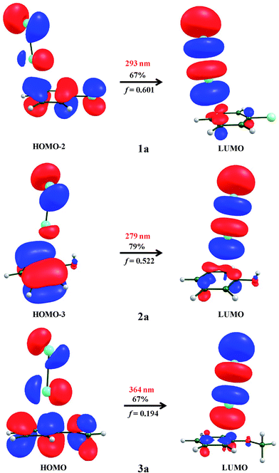
The formation of CT complexes between donor–acceptor molecules are confirmed through absorption parameters such as absorption maxima (λmax in nm). Notably, the absorption maxima (λmax in nm) of CT bands, which involve the transition from the π-orbital of the aromatic ring to the σ* orbital of I–I bond, need to be considered. In this regard, we employed the TD-DFT calculation43 using the ωB97x-D3 functional. The calculated λmax, vertical transition energies (ΔE, eV) and oscillator strengths (f) of both π and σ-type interactions are summarized in Table 4. Only the π-type of interaction (1a–3a) shows the CT transition band that is similar to the experimentally observed CT band with considerable oscillator strengths, while the halogen bonded type (1b–3b) does not show any type of CT absorption band. Therefore, the interaction between iodine and 1–3 is due to the formation of a π-complex type interaction (1a–3a). The computed absorption results show that 3a has an allowed CT band at 364 nm with an oscillator strength of 0.194. The observed experimental absorption band for 3a is at 360 nm. It is also noted that the calculated absorption band for 1a and 2a is 293 nm and 279 nm with the oscillator strength of 0.601 and 0.522, respectively. A detailed inspection of the MOs in Fig. 7 clearly shows that majority of the electronic distribution of the frontier molecular orbitals was found to be the transition from πCC → σ*(I2). Our computed TD-DFT-ωB97x-D3 absorption parameters are in good agreement with the CT band as observed in experiments. Based on our experimental and computed TDDFT-ωB97x-D3 absorption spectra along with the acoustic parameters, the atom-centered orientation is found to be preferred for 1a–3a.
 |
| | Fig. 7 Frontier molecular orbitals of the most prominent absorption of 1a–3a along with computed absorption maxima (λmax) and oscillator strength (f). | |
3.6 NBO analysis
The nature of non-covalent charge transfer interactions is often estimated by understanding the electronic wave functions of the occupied and unoccupied non-Lewis localized orbitals on the NBO basis.45,67,68 The second order perturbation interaction between the donor–acceptor orbital provides useful insights on the stability of charge transfer complexes.69 It is well known that charge transfer interaction is largely associated with the non-zero overlap between the benzene (donor) π-orbital and iodine (acceptor) σ* orbital. The lower electronegativity and larger sigma hole of the iodine molecule show higher stabilization interaction energy in both the σ- and π- type complexes of 1–3. Among the two types of complexes, the π-type complexes (1a–3a) are found to have higher second order interaction energies than the σ-type complexes (1b–3b). In the case of 3a, πCC → σ*(I2) is found to be the prominent interaction that leads to the stabilization energy of 44.94 kJ mol−1, whereas 2a is found to have similar weak interaction energies in the order of 44.71 kJ mol−1. In the case of 1a, πCC → σ*(I2) is found to be the less prominent interaction by 34.01 kJ mol−1 (Table 4). From Fig. 8, it is observed that in 1a–3a, the π-orbital of the substituted benzene ring interacts with the σ* orbital of the highly electrophilic iodine molecule, whereas in the case of the halogen bonded complexes (1b–3b), the interaction between the lone pair of heteroatoms (O atom in 2b and 3b and Cl atom in 1b) and the σ* orbital of the iodine molecule is explained. 1b is found to have a larger interaction energy than 2b and 3b. The order of the stabilizing interaction energies among 1a–3a is found to be: 3a > 2a > 1a. Again this is in excellent agreement with the trend observed in the stability of complex formation, which was observed by the acoustic, spectrophotometric methods and DFT computed interaction energies and supports the more favourable π-type complexes (1a–3a) over the less favourable σ-type complexes (1b–3b).
 |
| | Fig. 8 NBO computed orbital interactions corresponding to 1a–3a and 1b–3b of (a) πCC → σ*(I2) (b) nlp → σ*(I2). Second order interaction energies are presented in kJ mol−1. | |
4 Conclusions
The nature of the interactions that are present in three charge transfer (CT) complexes, namely, chlorobenzene–iodine (1), phenol–iodine (2) and anisole–iodine (3) have been investigated using ultrasonic, UV-Visible spectral and quantum chemical studies. Our results show the strong solute–solute interactions and charge transfer interactions that are present in these CT complexes. The decrease in the intermolecular free length (Lf) leads to a positive deviation in sound velocity (u) and negative deviation in isentropic compressibility (κs) in 1–3. Among the three CT complexes, the structure-breaking property of intermolecular hydrogen bonded phenol is predominant in 2 prior to the CT complex formation with iodine. This has been confirmed by the negative deviation in the speed of sound in a very dilute solution. Ultrasonic studies reveal that the order of magnitude of CT complex formation is 3 > 2 > 1 and this trend is confirmed by the stability constant (K) and free energy of formation (ΔG‡). which were calculated from the Benesi–Hildebrand method. DFT studies portray that the π-type complex is found to be energetically more favourable than the halogen bonded complex and the atom-centered orientation is found to be the preferred geometry. AIM and NBO analysis corroborate the predicted DFT results, which in turn well agree with the experimental findings. TDDFT results show that π → σ* transitions are responsible for the charge transfer nature of these CT complexes. In summary, it is established that the acoustic method can be employed as a simple and non-destructive tool to characterize the charge transfer non-covalent interactions that are present in CT complexes. The computed results are in good agreement with the experimental observations. Furthermore, the orientation of the iodine molecule depends on the substituent present in the aromatic ring. A further study on the influence of different types of substituents in the aromatic ring on the orientation of the iodine molecule is underway in our laboratory.
Acknowledgements
MJ thanks the Department of Science and Technology, New Delhi, India, for financial support through the DST Inspire Faculty Fellowship (Ref. no. IFA-13-CH-100) and FAST TRACK Young Scientist Award (DST SERB Ref. no. CS-353/2013 dated December 11, 2013). RK thanks the University Grants Commission (UGC), New Delhi, India, for financial assistance in the form of Minor Research Project (Ref. no. F.MRP-4418/13). Dr RVS & Dr MJ sincerely thanks Prof. P. Venuvanalingam, School of Chemistry, Bharathidasan University, Tiruchirappalli, India for the AIM analysis.
References
- D. S. Reddy, D. C. Craig and G. R. Desiraju, J. Am. Chem. Soc., 1996, 118, 4090–4093 CrossRef CAS.
-
(a) Y. X. Lu, Y. Wang and W. L. Zhu, Phys. Chem. Chem. Phys., 2010, 12, 4543–4545 RSC;
(b) K. S. Yeung, Drug Discovery Today, 2011, 15, 158 CrossRef PubMed.
- F. Yakuphanoglu and M. Arslan, Phys. B, 2007, 393, 304–309 CrossRef CAS PubMed.
- F. Yakuphanoglu and M. Arslan, Solid State Commun., 2004, 132, 229–234 CrossRef CAS PubMed.
- F. Guthrie XXVIII, J. Chem. Soc., 1863, 16, 239–244 RSC.
- H. A. Benesi and J. H. Hildebrand, J. Am. Chem. Soc., 1949, 71, 2703–2707 CrossRef CAS.
- R. S. Mulliken and W. B. Pearson, Molecular Complexes, Wiley Publishers, New York, 1969 Search PubMed.
- R. S. Mulliken, J. Am. Chem. Soc., 1950, 72, 600 CrossRef CAS.
- J. Collin and L. D'Or, J. Chem. Phys., 1955, 23, 397 CAS.
- H. Bai and B. S. Ault, J. Phys. Chem., 1990, 94, 199 CrossRef CAS.
- O. Hassel and K. Strømme, Acta Chem. Scand., 1958, 12, 1146 CrossRef CAS PubMed.
- L. Fredin and B. Nelander, J. Am. Chem. Soc., 1974, 96, 1672–1673 CrossRef CAS.
- L. Fredin and B. Nelander, Mol. Phys., 1974, 77, 885–898 CrossRef PubMed.
- E. E. Ferguson, J. Chem. Phys., 1956, 25, 577–578 CrossRef CAS PubMed.
- E. E. Ferguson, Spectrochim. Acta, 1957, 10, 123–124 CrossRef.
- J. C. Shug and M. C. Dyson, J. Chem. Phys., 1973, 58, 297 CrossRef PubMed.
- R. E. Bruns, J. Mol. Struct., 1977, 36, 121–126 CrossRef CAS.
- A. M. Mebel, H. L. Lin and S. H. Lin, Int. J. Quantum Chem., 1999, 72, 307–318 CrossRef CAS.
- K. Weng, Y. Shi, X. Zheng and D. L. Phillips, J. Phys. Chem. A, 2006, 110, 851–860 CrossRef CAS PubMed.
- S. S. C. Ammal, S. P. Ananthavel, P. Venuvanalingam and M. S. Hegde, J. Phys. Chem. A, 1998, 102, 532–536 CrossRef CAS.
- A. K. Nain, J. Chem. Thermodyn., 2013, 59, 49–64 CrossRef CAS PubMed.
- T. Zhao, J. Zhang, L. Li, B. Guo, L. Gao and X. Wei, J. Mol. Liq., 2014, 198, 21–29 CrossRef CAS PubMed.
- D. L. Cunha, J. A. P. Coutinho, J. L. Daridon, R. A. Reis and M. L. L. Paredes, J. Chem. Eng. Data, 2013, 58, 2925–2931 CrossRef CAS.
- A. Ali, A. K. Nain, V. K. Sharma and S. Ahmad, Phys. Chem. Liq., 2004, 42, 375–383 CrossRef CAS PubMed.
- R. Kumar, S. Jayakumar and V. Kannappan, Fluid Phase Equilib., 2013, 360, 309–319 CrossRef CAS PubMed.
- R. Kumar, G. Padmanabhan, V. Ulagendran, V. Kannappan and S. Jayakumar, J. Mol. Liq., 2011, 162, 141–147 CrossRef CAS PubMed.
- R. Kumar, A. Justin Adaikala Baskar, V. Kannappan and D. Roop Singh, J. Mol. Liq., 2014, 196, 404–410 CrossRef CAS PubMed.
- R. Kumar, S. Jayakumar and V. Kannappan, Thermochim. Acta, 2012, 536, 15–23 CrossRef CAS PubMed.
- S. R. Salman, S. J. Titinchi, H. S. Abbo and A. A. Saeed, Spectrosc. Lett., 1990, 23, 447–457 CrossRef CAS PubMed.
- E. Y. Frag and G. G. Mohamed, J. Mol. Struct., 2010, 979, 46–55 CrossRef CAS PubMed.
-
(a) V. Ulagendran, R. Kumar, S. Jayakumar and V. Kannappan, J. Mol. Liq., 2009, 148, 67–72 CrossRef CAS PubMed;
(b) V. Kannappan and N. Indra Gandhi, Phys. Chem. Liq., 2008, 46, 510–515 CrossRef CAS PubMed.
- F. C. Küpper and P. M. H. Kroneck, Iodine Bioinorganic Chemistry, ed. T. Kaiho, John Wiley & Sons Interscience, 2015, ch. 32, pp. 555–589 Search PubMed.
- B. L. Marwein and S. N. Bhatt, Thermochim. Acta, 1987, 118, 277–285 CrossRef CAS.
- M. J. Frisch, G. W. Trucks, H. B. Schlegel, G. E. Scuseria, M. A. Robb, J. R. Cheeseman, G. Scalmani, V. Barone, B. Mennucci, G. A. Petersson and H. Nakatsuji, et al., Gaussian 09, Revision B.01, Gaussian, Inc., Wallingford, CT, 2009 Search PubMed.
- F. Neese, Density Functional and Semi Empirical Program Package, version 2.8, University of Bonn, Bonn, Germany, 2009 Search PubMed.
- J. P. Perdew and W. Yue, Phys. Rev. B: Condens. Matter Mater. Phys., 1986, 33, 8800–8802 CrossRef.
- D. Becke, Phys. Rev., 1988, 3098–3100 Search PubMed.
- S. Grimme, J. Antony, S. Ehrlich and H. Krieg, J. Chem. Phys., 2010, 132, 15104 CrossRef PubMed.
-
(a) C. Lee, W. Yang and R. G. Parr, Phys. Rev. B: Condens. Matter Mater. Phys., 1988, 37, 785–789 CrossRef CAS;
(b) D. Becke, J. Chem. Phys., 1993, 98, 5648–5652 CrossRef PubMed.
- D. A. Pantazis and F. Neese, Theor. Chem. Acc., 2012, 131, 1292 CrossRef.
- S. F. Boys and F. Bernardi, Mol. Phys., 1970, 19, 553–557 CrossRef CAS PubMed.
- A. Klamt and G. J. Schüürmann, J. Chem. Soc., Perkin Trans. 2, 1993, 799–805 RSC.
- A. Dreuw and M. Head-Gordon, Chem. Rev., 2005, 105, 4009–4037 CrossRef CAS PubMed.
- E. Glendening, A. Reed, J. Carpenter and F. Weinhold, NBO, University of Wisconsin, Madison, WI, 1998 Search PubMed.
- A. E. Reed, L. A. Curtiss and F. Weinhold, Chem. Rev., 1988, 88, 899–926 CrossRef CAS.
- J.-D. Chai and M. Head-Gordon, Phys. Chem. Chem. Phys., 2008, 10, 6615–6620 RSC.
-
(a) J. M. L. Martin and A. Sundermann, J. Chem. Phys., 2001, 114, 3408–3420 CrossRef CAS PubMed;
(b) J. Tomasi and M. Persico, Chem. Rev., 2027, 1994, 94 Search PubMed;
(c) J. Tomasi and R. Cammi, J. Comput. Chem., 1995, 16, 1449 CrossRef PubMed;
(d) M. Cossi, V. Barone, R. Cammi and J. Tomasi, Chem. Phys. Lett., 1996, 255, 327 CrossRef CAS.
- F. Biegler-König, J. Schönbohm and D. Bayles, AIM2000, J. Comput. Chem., 2001, 22, 545–559 CrossRef.
- A. Awasthi, M. Rastogi, M. Gupta and J. P. Shukla, J. Mol. Liq., 1999, 80, 77 CrossRef CAS.
- B. D. Nageshvara Rao, P. V. Venkatesawaralu, A. S. N. Murthy and C. N. R. Rao, Can. J. Chem., 1962, 40, 963–965 CrossRef.
- L. Palaniappan, Phys. B, 2008, 403, 3887–3891 CrossRef PubMed.
- S. L. Oswal, V. Pandiyan, B. Krishnakumar and P. Vasantharani, Thermochim. Acta, 2010, 27, 507–508 Search PubMed.
- R. Thiyagarajan, M. S. Jaafar and L. Palaniappan, J. Phys. Sci., 2007, 18, 81–88 CAS.
- B. Dalai, S. K. Dash and S. K. Singh, Indian J. Pure Appl. Phys., 2014, 52, 24–29 CAS.
- Y. Reddy, P. S. Naidu and K. Ravindra Prasad, Indian J. Pure Appl. Phys., 1994, 32, 958–963 Search PubMed.
- V. Pandiyan, S. L. Oswal and P. Vasantharani, Thermochim. Acta, 2011, 516, 64–73 CrossRef CAS PubMed.
- R. J. Fort and M. W. R. Moore, Trans. Faraday Soc., 1965, 61, 2102–2111 RSC.
- R. R. Naik and S. V. Bawankar, African Journal of Science and Research, 2014, 3, 1–3 Search PubMed.
- A. Ali and A. K. Nain, Bull. Chem. Soc. Jpn., 2002, 75, 681–687 CrossRef CAS.
- C. Wang, D. Danovich, Y. Mo and S. Shaik, J. Chem. Theory Comput., 2014, 10, 3726–3737 CrossRef CAS.
- R. F. W. Bader, Chem. Rev., 1991, 91, 893–928 CrossRef CAS.
- R. F. Bader, J. Phys. Chem. A, 2009, 113, 10391–10396 CrossRef CAS PubMed.
- R. Vijay Solomon, S. A. Vedha and P. Venuvanalingam, Phys. Chem. Chem. Phys., 2014, 16, 7430–7440 RSC.
- M. Sundararajan, R. Vijay Solomon, S. K. Ghosh and P. Venuvanalingam, RSC Adv., 2011, 1, 1333–1341 RSC.
- A. Mohajeri and F. F. Nobandegani, J. Phys. Chem. A, 2008, 112, 281–295 CrossRef CAS PubMed.
-
(a) E. Espinosa, I. Alkorta, J. Elguero and E. Molins, J. Chem. Phys., 2002, 117, 5529–5542 CrossRef CAS PubMed;
(b) E. Espinosa, E. Molins and C. Lecomte, Chem. Phys. Lett., 1998, 285, 170–173 CrossRef CAS.
- A. E. Reed and F. Weinhold, J. Chem. Phys., 1985, 83, 1736–1741 CrossRef CAS PubMed.
- W. Wang, N. B. Wong, W. Zheng and A. Tian, J. Phys. Chem. A, 2004, 108, 1799–1805 CrossRef CAS.
- R. Vijay Solomon, P. Veerapandian, S. Angeline Vedha and P. Venuvanalingam, J. Phys. Chem. A, 2012, 116, 4667–4677 CrossRef PubMed.
Footnote |
| † Electronic supplementary information (ESI) available: The corresponding UV-Visible spectrum for 1–3 with I2 and optimized geometries of all of the molecules along with their XYZ coordinates. See DOI: 10.1039/c5ra03297k |
|
| This journal is © The Royal Society of Chemistry 2015 |
Click here to see how this site uses Cookies. View our privacy policy here. 
 and b is a constant. Its value is 2; R is the universal gas constant; K is a temperature independent constant, which is equal to 4.28 × 10⁹ for all liquids, u is ultrasonic velocity and ρ is the measured density.