Thermochemical recovery technology for improved modern engine fuel economy – part 1: analysis of a prototype exhaust gas fuel reformer

D. Fennella, J. Herrerosa, A. Tsolakis*a, K. Cockleb, J. Pignonb and P. Millingtonb
aSchool of Mechanical Engineering, University of Birmingham, Edgbaston, Birmingham, B15 2TT, UK. E-mail: a.tsolakis@bham.ac.uk; Tel: +44 (0)121 414 4170
bJohnson Matthey Technology Centre, Blount's Court, Sonning Common, Reading, RG4 9NH, UK

Received 18th February 2015 , Accepted 7th April 2015

First published on 7th April 2015


Abstract

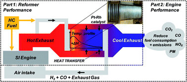
Exhaust gas fuel reforming has the potential to improve the thermal efficiency of internal combustion engines, as well as simultaneously reduce gaseous and particulate emissions. This thermochemical energy recovery technique aims to reclaim exhaust energy from the high temperature engine exhaust stream to drive catalytic endothermic fuel reforming reactions; these convert hydrocarbon fuel to hydrogen-rich reformate. The reformate is recycled back to the engine as Reformed Exhaust Gas Recirculation (REGR), which provides a source of hydrogen to enhance the engine combustion process and enable high levels of charge dilution; this process is especially promising for modern gasoline direct injection (GDI) engines. This paper presents a full-scale prototype gasoline reformer integrated with a multi-cylinder GDI engine. Performance is assessed in terms of the reformate composition, the temperature distribution across the catalyst, the reforming process (fuel conversion) efficiency and the amount of exhaust heat recovery achieved.

1. Introduction

Exhaust gas fuel reforming is a technique with potential to achieve energy recovery from the exhaust stream of internal combustion engines in order to raise the engine thermal efficiency and reduce fuel consumption, as well as reduce exhaust emissions.1–3 The feasibility of this thermochemical energy recovery process relies on ensuring that the overall process is endothermic and energy is captured from the exhaust stream. The major reforming reactions are listed in Table 1. The two primary chemical reactions, steam reforming (1) and dry reforming (2) are endothermic and reform hydrocarbon (HC) fuel into hydrogen and carbon monoxide with a net gain in fuel enthalpy. Carbon dioxide and steam are supplied as reactants by the engine exhaust gas, and the hydrogen-rich product gases are re-circulated to the intake system for in-cylinder combustion, completing the reformed exhaust gas recirculation (REGR) system.
Table 1 General formulae for the key reforming reactions in hydrocarbon fuel reforming
Reaction General chemical formula Enthalpy of reactiona, MJ kmol−1
a When calculating enthalpy of reaction it was assumed that: HC fuel is n-octane; reactions go to completion; products and reactants are at 25 °C and 1 atm; and water is in the gaseous state. Thermodynamic data from ref. 5.
Steam reforming image file: c5ra03111g-t1.tif ΔhR = (+1259) (1)
Dry reforming image file: c5ra03111g-t2.tif ΔhR = (+1588) (2)
Combustion image file: c5ra03111g-t3.tif ΔhR = (−5116) (3)
Partial oxidation image file: c5ra03111g-t4.tif ΔhR = (−676) (4)
Water-gas shift CO + H2O ⇌ CO2 + H2 ΔhR = (−283) (5)


If oxygen is present in the exhaust gas then some fuel will be consumed by highly exothermic oxidation reactions. Previous exhaust gas fuel reforming studies4 have revealed that the combustion reaction (3) prevails but some partial oxidation (4) is also possible. In some applications the oxidation reactions are used to increase the catalyst temperature in order to improve the hydrogen yield, for instance by partial oxidation reformers and autothermal reformers. The less exothermic water-gas shift (WGS) reaction (5) also increases the hydrogen concentration by reacting CO, which has already been produced by the other reforming reactions, with steam. The process efficiency is reduced to some degree by these exothermic reactions.

Other classifications of reformer have been researched for on-board hydrogen generation in the past. Partial oxidation reformers5–7 react air and HC fuel to produce reformate, which, when coupled with a gasoline engine, can extend the (air or EGR) dilution limit and improve engine efficiency and emissions. These systems can be useful for cold engine starts operating partially or solely on reformate in order to reduce emissions during warm-up.6,7 However, the engine-reformer system efficiency ultimately suffers due to energy lost in the exothermic partial oxidation reforming process. A plasma reformer8,9 instead uses electrical power to convert HC fuels to reformate. Again, the overall engine-reformer system efficiency is reduced due to the electrical power required for the reforming process. None of these systems aim to achieve exhaust heat recovery.

Ethanol reformers designed to achieve heat recovery from ethanol-fuelled10 and gasoline-fuelled11 SI engines have been developed more recently. Ethanol can be reformed more easily than the longer chain and more complex (e.g. aromatic) HC components of gasoline and so it is possible at lower temperature, typically between 300 and 350 °C.10 This makes ethanol reforming feasible over most of the operating range of a SI engine.

The gasoline reformer has potential for more widespread use than ethanol and E85 but greater technical barriers to overcome, most notably with respect to achieving effective performance at sufficiently low temperature to be feasible with the gasoline engine exhaust stream. Because reformer performance is heavily dependent upon catalyst temperature, reformer design should be focussed to ensure efficient heat transfer from the exhaust stream and minimise heat loses.4,12

Exhaust gas fuel reforming has great potential for improving engine efficiency and reducing exhaust emissions. A review article by Golunski13 discussed the application of exhaust gas fuel reforming for improving the thermal efficiency of IC engines through enhanced combustion and novel after-treatment solutions. Thermodynamic and experimental studies of the REGR reactions have shown that precious metal catalysts, e.g. rhodium on zirconia,14,15 exhibit high activity with yields close to equilibrium at temperatures typical of the gasoline engine exhaust. A recent experimental study1 using hydrogen and CO addition to conventional EGR highlights the potential benefits that REGR can offer to the GDI engine, with simultaneous reductions in NOx, PM and CO, only slightly increased HCs, and increased engine and total system thermal efficiency.

This paper furthers the research in the field of exhaust gas fuel reforming as, for the first time, a full-scale gasoline reformer integrated with a modern production multi-cylinder GDI engine was studied. The results discussed in this paper are focussed on the prototype reformer performance; this includes examination of the reformer temperature profiles, analysis of the reformate composition including HC speciation, and calculation of the reformer fuel conversion efficiency. Devices designed to achieve exhaust heat recovery may be subjected to exergy analysis, and this has been applied here to establish the influence of exhaust gas fuel reforming on the exergy, or ‘available energy’, of the exhaust stream. The efficiency and emissions performance of the GDI engine utilising exhaust gas fuel reforming will be presented in a follow-up paper.

2. Experimental setup and test conditions

The reformer and catalyst were designed by Johnson Matthey and it consists of a stack of five metallic catalyst plates (8.8 in3 each) coated with 3.6 g in−3 of ceramic support (ceria–zirconia–alumina) loaded with 3.3% platinum – 1.7% rhodium. Rhodium offers very good sulphur tolerance, excellent thermal stability and resistance to coking, and stable catalyst performance was experienced throughout the 6 month test program. Each catalyst plate is mounted between two finned stainless steel plates used to seal it from the exhaust stream. The reformer plate assembly was designed to ensure high heat transfer from the hot exhaust gas to the catalyst, using fins on the stainless steel surround for increased surface area and a narrow catalyst construction only four cells thick. The exhaust stream flows over the reformer plate stack, which is positioned after the TWC. The reformer feed gas is extracted from the exhaust stream before the TWC, mixed with gasoline, and routed around the outer skin of the TWC to assist with fuel vaporisation and feed gas pre-heating. The required flow rate of gasoline was injected into the reformer feed gas by varying the pulse-width of a solenoid fuel injector, typically used in port injection engines, operating at a fixed frequency of 30 Hz. The injector was mounted to the reformer with a manifold cooled by engine water to protect the injector from high exhaust system temperatures. 11 thermocouples were distributed over the middle reformer plate according to schematic Fig. 1, with additional thermocouples in the feed gas, product gas, and exhaust stream before and after passing over the reformer assembly.
image file: c5ra03111g-f1.tif
Fig. 1 Reformer schematic indicating thermocouples (TC) locations on the central reformer plate and in the exhaust stream.

Reformer installation

The reformer was installed with a turbocharged 2L GDI engine, positioned in the exhaust stream after the TWC. The REGR system installation used a ‘high pressure’ recirculation configuration, inducting reformate directly into the intake manifold. The system consisted of an integrated DC motor controlled EGR valve and cooler, and an additional cooler, all supplied with engine coolant to maintain acceptable gas and component temperatures.

Reformate analysis

A MKS Instruments Multigas 2030 Fourier Transform Infra-Red (FTIR) spectrometer was used to analyse the reformate stream for multiple species, including CO2, CO, H2O, NH3 and a selection of hydrocarbons compounds including methane. A HP 5890 Series 2 gas chromatograph with thermal conductivity detector (GC-TCD) and HP 3395 integrator was used to measure the hydrogen concentration in the reformate stream. Argon at 40 psi acted as the carrier gas to the sample fed at 10 psi, resulting in the hydrogen peak occurring at 2.4 s retention time. The detector was calibrated with 10% and 30% hydrogen in nitrogen. Another HP 5890 Series 2 gas chromatograph with flame ionisation detector (GC-FID) gave in-depth speciation of the HC components of the reformate. The GC-FID was calibrated with 15 common HCs ranging from C1 to C7 (Table 2).
Table 2 Hydrocarbon species included in GC-FID calibration
HC species Formula HC species Formula HC species Formula
Methane CH4 1-Butane C4H10 n-Pentane C5H12
Ethylene C2H4 1,3-Butadiene C4H6 n-Hexane C6H14
Propylene C3H6 n-Butane C4H10 Benzene C6H6
Propane C3H8 3-Methyl-1-butene C5H8 n-Heptane C7H16
Iso-butane C4H10 Iso-pentane C5H12 Toluene C7H8


A Horiba MEXA-7100DEGR measured the intake manifold and exhaust stream CO2 concentration in order to calculate the charge dilution rate according to eqn (6). The FID component of the Horiba analyser was also useful for providing a measurement of the total HC content of the reformate, which was not possible with the FTIR analyser.

 
image file: c5ra03111g-t5.tif(6)

Test conditions

Three engine conditions were selected in order to generate a suitable range of reformer temperature and flow conditions; these were 35 Nm/3 bar IMEP at 2100 rpm, 50 Nm/4 bar IMEP at 3000 rpm, and 105 Nm/7.2 bar IMEP at 2100 rpm. The first two conditions are key steady state conditions used on the new European drive cycle for a mid-size/large family vehicle with a 2 litre engine, and the third condition is typical of a higher load transient condition. At each condition the engine was operated with the maximum achievable charge dilution rate, and also a lower dilution rate to investigate the effect of reformer mass flow rate, or gas hourly space velocity (GHSV). Gasoline was injected into the reformer feed gas such that the molar concentration was 0.5% and 1% (fuel composition assumed to be octane) to test the influence of fuel concentration on reformer performance. Excess fuel can result in a reversible catalyst deactivation by coke lay down. The fuel addition was optimised to avoid this fouling while maintaining good H2 production and the test procedure involved periodically operating with EGR to expose the catalyst to steam and oxygen in order to reverse any coking that may have occurred.

The engine-out exhaust gas composition (Table 3) varied little across the range of conditions tested because the engine uses a homogeneous, stoichiometric combustion strategy. This can also be considered the reformer feed gas composition (prior to gasoline injection). The slight variations of the primary exhaust gas species at each engine condition are due to the use of different charge dilution rates which influenced the combustion. This also results in larger percentage variation of NOx and THCs due to the effects of REGR on the combustion process. The oxygen content of the exhaust stream varies only between 0.5 to 0.7%, which is of particular relevance to the reformer process efficiency as the oxygen concentration is directly proportional to the amount of fuel that is oxidised in the reformer and the resulting increase in temperature.

Table 3 Exhaust gas temperature (EGT) and composition at each engine condition
Engine condition EGT, °C (pre-reformer) CO2, % O2, % CO, % aH2O, % NOx, ppm THC, ppm
a Calculated.
35 Nm/2100 rpm 595–605 14.8–15.0 0.60–0.70 0.50–0.60 14.3–14.4 100–1200 1900–3000
50 Nm/3000 rpm 655–680 14.8–14.9 0.50–0.65 0.50–0.55 14.3–14.4 200–600 1500–1900
105 Nm/2100 rpm 685–720 14.8–15.0 0.60–0.65 0.55–0.70 14.4–14.5 900–2300 1300–1600


3. Results and discussion

3.1 Reformate characteristics

Temperature distribution. The temperature distribution across the middle reformer plate varies with engine condition, REGR flow rate, fuel concentration, and the resulting reforming activity (Fig. 2). In these plots the reformer feed gas flows from top to bottom and the engine exhaust stream flows over the plate from right to left. The temperatures were generally higher along the right edge due to the exhaust stream heating. The baseline plots clearly show that the reformer plates are more effectively heated as the exhaust stream temperature increases with engine load.
image file: c5ra03111g-f2.tif
Fig. 2 Temperature (°C) distribution across the middle reformer plate at (a) 35 Nm, (b) 50 Nm and (c) 105 Nm engine conditions, for a range of REGR concentrations (vol) in the intake charge with either 0.5% or 1% (vol) gasoline in the reformer feed gas.

At the lowest temperature condition (35 Nm/2100 rpm) the plate temperatures drop as the REGR flow is increased up to 20% due to reforming activity. There is also a slight cooling effect just by flowing gas through the reformer (i.e. with EGR), analogous to a forced-convection cooling process. At the highest REGR flow rate there is a slight increase in reformer temperature with a more even distribution. This is the result of multiple effects associated with increasing the flow rate: more oxygen is available for fuel oxidation which increases the gas temperature in the front of the reformer; the high flow rate moves the high temperature gas along the reformer more quickly resulting in the more even distribution; and reforming activity tends to be lower as the flow rate increases.

At the two higher engine load conditions the reformer is heated to significantly higher temperature when there is no REGR flow (baseline condition). Increasing either the REGR flow or the fuel concentration lowers the reformer temperature. Both of these changes increase the availability of fuel while, importantly, at sufficiently high temperature for the endothermic reforming reactions to be feasible. Again, increasing the REGR flow rate results in a more even temperature distribution.

Linear reformer temperature profiles. Fig. 3 compares the linear reformer temperature profiles while reforming with two different mass flows, 4.5 and 14.5 kg h−1 – this equates to 10% and 25% REGR in terms of the dilution rate at the 35 Nm/2100 rpm engine condition. Temperature profiles are included for 0.5% and 1% fuel in the reformer feed gas. At low reactant mass flow rate in the reformer, there was very little heating due to exothermic reactions in the front of the catalyst. There was no indication of endothermic reforming cooling the reformer. It appears that a small amount of reforming occurred in the first 75 mm of the reformer as the temperature remains approximately constant. After this the temperature increased due to heating by the main engine exhaust stream. At the higher reactant flow rate there was a greater quantity of fuel and oxygen passing through the reformer which led to a larger temperature increase at the front face. The combination of higher temperature and more fuel being available for reforming meant that there was a clear drop in temperature along the length of the reformer due to endothermic reforming reactions.
image file: c5ra03111g-f3.tif
Fig. 3 Linear reformer temperature profile at the low temperature (35 Nm/2100 rpm) condition.

Increasing the fuel concentration in the feed gas (for a given reactant flow rate) results in a reasonably uniform reduction of the temperature along the reformer. The feed gas temperature (−30 mm from leading edge) was slightly lower for the higher fuel flow conditions due to greater cooling by fuel vaporisation, and the gradient of the rise in temperature between the feed gas (−30 mm) and the leading edge (0 mm) was similar when comparing each fuel concentration condition. The amount of oxygen available for oxidation is dependent on the reactant flow rate and determines the amount of heating at leading edge. The slight reduction of heating with increasing fuel concentration is likely due to the higher rate of endothermic reforming (decrease in the oxygen/carbon ratio) and slightly higher specific heat capacity of the feed gas.

The effect of reactant mass flow rate in the reformer on the linear temperature profile is shown in Fig. 4 for two engine loads with 1% feed gas fuel concentration in each case. This shows the location of endothermic reforming moving further along the reformer with increasing flow rate. The initial drop in temperature is greater for the lower flow condition at each load.


image file: c5ra03111g-f4.tif
Fig. 4 Linear reformer plate temperature profiles for high and low REGR flows at two engine conditions (1% feed gas fuel concentration in each case).

When the reformer flow is low and the reformer plate temperature is relatively high at the inlet, 650 °C at the 105 Nm condition, most of the reforming occurs in the first section of the reformer and is followed by re-heating. This implies that the reformer is able to process more fuel than is being supplied at the low flow condition.

Comparing the two curves for the high temperature condition (105 Nm) there is a large temperature difference in the final 100 mm of the reformer. The conditions in this section can be used to give an insight into the equilibrium position of the WGS reaction. The reformer temperature is reduced for the higher REGR rate which increases the WGS reaction equilibrium constant, resulting in an equilibrium shift towards higher H2 and CO2 concentration by consuming CO and H2O. For this reason, increasing the REGR rate generally results in a greater hydrogen/CO ratio (providing conditions are reasonable for reforming) this can be seen by comparing the hydrogen and CO data in Fig. 5, particularly for the 1% feed gas fuel concentration conditions.


image file: c5ra03111g-f5.tif
Fig. 5 Reformate species concentrations at various engine conditions (a) 35 Nm, (b) 50 Nm and (c) 105 Nm.

It should be emphasised that the linear profiles offer a 1-dimensional view of the reformer operating temperature. This information disregards the temperature distribution across each reformer plate and any difference between the five individual plates.

Reformate speciation. Maximum hydrogen production was observed when the consumption of steam was greatest, which indicates successful promotion of the steam reforming reaction (Fig. 5). This occurred at the 50 Nm/3000 rpm engine condition, when there was 11% hydrogen produced and 6% un-reacted steam measured in the reformate, and there was a combination of high temperature and intermediate reactant flow rate. Some CO2 can be expected to be produced by oxidation and WGS reactions, and may be consumed by the dry reforming reaction. The CO2 concentration in the reformate was relatively consistent at most test points but was reduced slightly for low REGR mass flow rates. It should be noted that for a given engine load, at lower REGR mass flows the reformer plate temperatures are higher. This means the reversible WGS reaction has a smaller equilibrium constant, is therefore less favourable towards the reaction products, and so less hydrogen and CO2 are produced by this reaction.
Hydrocarbon speciation. The proportion of HCs that breakthrough the reformer increases with REGR flow rate; therefore at 17 kg h−1 REGR (Fig. 6a) there is a lower total HC (THC) concentration. The calibration gas used contains many of the major components (Table 2) of gasoline and there were no significant peaks in the chromatogram spectrum unaccounted for.
image file: c5ra03111g-f6.tif
Fig. 6 Proportion of HC species of the total HCs in reformate as measured by GC-FID at 50 Nm/3000 rpm with REGR (1% fuel): 17 kg h−1 (a) and 24 kg h−1 (b).

Methane made up a greater proportion of the HCs in the reformate at lower REGR flow, partly because the total breakthrough HC quantity was lower, but also due to higher methane production by the ‘methanation’ reforming side reactions; these consume hydrogen in reactions with CO, CO2 or HCs to produce methane, but tend to be relatively unfavoured under REGR conditions.14 The higher concentration of H2 and CO produced by the primary reforming reactions at lower REGR flow will lead to the methanation reactions being increasingly favoured.

The molar composition of the gasoline was 12.6% paraffins, 33.4% isoparaffins, 14.6% olefins, 5.1% naphthenes, 28.9% aromatics and 4.9% oxygenates. The measured aromatic fraction (benzene + toluene) was higher in each case at 37% and 51%. This supports the idea that the aromatic fraction of the gasoline is not being reformed as readily as the less complex HCs such as the paraffins, which constitute nearly half of the gasoline mixture and appear in significantly lower quantity in the reformate. There is also a smaller toluene/benzene ratio at low reactant flow which implies toluene is reformed more readily than benzene. It may be that some toluene is partially reformed to the more stable/less reactive benzene.

3.2 Reformer process efficiency

The effectiveness of the reformer can be analysed by calculating the reformer process efficiency using eqn (7). In this equation the HCs and CO contained in the engine exhaust gas which is fed in the reformer are not included in the calculation of the reformer efficiency. However, they are supplied to the reformer as products of incomplete in-cylinder combustion, and would usually be considered wasted energy as the exhaust heat, being both uncombusted species and exhaust heat being used in the reformer. Therefore eqn (7) calculates reformer process efficiency without including those species as an input energy, contributing in the increase of the reforming process efficiency (Fig. 7). ‘Dry’ measurements were converted to ‘wet’ molar fractions (using knowledge of the steam concentration in the feed gas/reformate) before calculating the mass flow rate of individual species.
 
image file: c5ra03111g-t6.tif(7)

image file: c5ra03111g-f7.tif
Fig. 7 Reformer process efficiency (a & b) and fuel enthalpy increase (c & d) plotted against REGR mass flow (a & c) and exhaust temperature at the reformer inlet (b & d).

At the two highest engine load conditions, when exhaust temperature is above 650 °C, the reformer process efficiency is greater than one (Fig. 7a and b). This means that the overall reforming reaction is an endothermic process leading in the increase of the total fuel enthalpy (Fig. 7c and d). The reformer process efficiency is similar when comparing fuel concentration at each test point; increasing the fuel concentration to 1% improves further the fuel enthalpy. At the low temperature condition the reformer process efficiency is less than 1, meaning some energy is lost during the gasoline reforming process.

3.3 Exhaust energy recovery

First law analysis – exhaust stream energy. Under normal engine operating conditions, i.e. when there is no reforming, the exhaust stream temperature drops (by some amount ΔT) as it passes across the reformer due to heat loss to the atmosphere. This is perhaps an obvious statement; however it is necessary to consider this heat loss when estimating the amount of exhaust energy recovery achieved by the reformer. When operating with EGR or REGR at a given engine load and recirculation rate, the exhaust stream mass flow, composition, and temperature at the reformer inlet are very similar; therefore it may be assumed that the heat loss to atmosphere is the same under each condition.

When the reformer is switched on there will be a greater exhaust stream temperature differential (ΔTREGR) if energy is extracted by the overall endothermic reforming process. This means that the exhaust stream temperature drop due to reforming, ΔTRef can be estimated for each condition using ΔTRef = ΔTREGR − ΔTEGR. The rate of exhaust heat recovery is then approximately equal to the change in enthalpy of the exhaust gases as they drop in temperature by ΔTRef, and is calculated using eqn (8). The specific heat capacity of the exhaust stream, cexh, was calculated for the mixture of nitrogen, CO2 and steam (post-TWC composition) at the average of the pre- and post-reformer exhaust stream temperature.

 
Exhaust heat recovery, [Q with combining dot above] = = exh[c with combining macron]p,exhΔTRef (kW) (8)

The rate of exhaust stream heat recovery achieved by fuel reforming at each engine condition is plotted in Fig. 8. The highest rate of heat recovery was achieved at the 105 Nm engine condition when the reformer temperature was highest. This engine condition uses intermediate REGR mass flow rates and so the reformer's ability to recover exhaust energy is not compromised by high GHSV. At the 50 Nm engine condition, increasing the REGR flow to the highest rate reduces heat recovery due to the combined effects of increased GHSV and lower exhaust stream temperature (increased charge dilution causes lower combustion and exhaust temperatures). In general, increasing the reformer fuel flow increases the amount of exhaust heat recovery.


image file: c5ra03111g-f8.tif
Fig. 8 Rate of exhaust stream heat recovery with fuel reforming.

While considering the heat recovery in absolute terms is interesting, it is also important to put these values into perspective; Fig. 9 presents the heat recovery as a fraction of the total fuel energy, engine effective work and pre-reformer exhaust stream energy. When working close to optimally at the 50 Nm and 105 Nm conditions, the reformer is able to extract energy from the exhaust stream to recover around 1% of the total fuel energy supplied to the engine and reformer, which equates to between 3-4% of the effective engine work.


image file: c5ra03111g-f9.tif
Fig. 9 Exhaust stream heat recovery as a fraction of total fuel energy, engine effective work and pre-reformer exhaust energy.
Second law analysis – exhaust stream exergy. According to the second law of thermodynamics, exergy represents the maximum amount of energy that can be extracted by bringing a system at temperature T to the ambient temperature T0. The exergy of a fluid stream can be evaluated using eqn (9).16 This considers the exergy of the enthalpy, kinetic energy and potential energy of the fluid stream. This analysis was applied to the exhaust stream, which contains multiple gas species, using eqn (10) to calculate the ‘energy availability’ of the pre- and post-reformer exhaust gas, where exh is the molar flow of the exhaust stream (kmol s−1) and ni is the molar fraction of gas species i. In this case, T0 was taken as 298 K.
 
image file: c5ra03111g-t7.tif(9)
 
ψexh = ∑exhni[(hihi,0) − T0(sisi,0)] (kW) (10)

There were various assumptions made during the calculation of exhaust exergy. These included: the exhaust stream is a mixture of ideal gases; specific heat values are taken at the average process temperature, and were calculated using 3rd order polynomial relationships from;16 the TWC catalyst converts the exhaust stream to a mixture of inert gases (nitrogen, carbon dioxide and steam) with 100% efficiency and therefore the exhaust contains no species with chemical potential energy; the exergy of the kinetic and gravitational potential energy components of the exhaust stream are negligible.

As the reformer is designed to recover energy from the exhaust stream, there should be a reduction in exergy, or available energy, across the reformer. A more efficient overall engine-reformer system should also result in a reduction of the exhaust stream exergy (for a given load) at the reformer inlet. This accounts for the influence of REGR on the engine and combustion efficiency, which directly influences the exhaust exergy.

Fig. 10 plots the pre- and post-reformer exhaust stream exergy, as a percentage of the engine brake power, for each test condition at each engine load. These plots show the general trend for reducing exhaust stream exergy with increasing dilution rate and reformed fuel fraction. In each case the baseline condition exhaust exergy is highest; both EGR and REGR reduce the exhaust exergy. The 50 Nm engine condition represents the highest ‘relative’ exergy with 60% of the brake power available for recovery; the highest absolute exergy was at the 105 Nm condition.


image file: c5ra03111g-f10.tif
Fig. 10 Comparing pre- and post-reformer exhaust stream exergy for a variety of engine conditions (a) 35 Nm, (b) 50 Nm and (c) 105 Nm.

4. Conclusions

A full-scale prototype exhaust gas fuel reformer has been coupled with a multi-cylinder GDI engine, and demonstrates that gasoline reforming is feasible as a thermochemical energy recovery technique at typical GDI engine exhaust temperature.

At higher exhaust temperatures, the reformer is capable of converting gasoline to hydrogen-rich gas in an overall endothermic process while recovering some exhaust energy. Performance is borderline effective at lower exhaust temperature (for engine conditions representing low vehicle speed); this means that some reforming is possible which produces hydrogen that is beneficial to engine operation, but a small amount of fuel energy is lost in the reforming process.

Speciation of reformate produced by the reformer at a range of engine conditions indicates a large variation in reformate quality, with a strong dependence on process temperature and reactant composition.

The outlook for fuel reforming may be improved should the trend for engine downsizing continue. By placing a higher demand on the engine by downsizing, there is a shift to higher engine IMEPs for a given road load and the mean exhaust temperature will be increased as a result. It can be concluded from this study is that sustained (medium) engine loads, as used for motorway/highway driving, generate conditions that favour fuel reforming; ultimately this means that exhaust energy recovery can be achieved. The bias of many drive cycles to low engine speed/load conditions, and a high proportion of warm-up time, mean that the fuel reformer is not likely show its full potential ‘on cycle’ but should offer greater benefits for higher load and sustained driving conditions.

Abbreviations

TDCTop dead centre
COCarbon monoxide
EGRExhaust gas recirculation
EGTExhaust gas temperature
FTIRFourier transform infra-red detector
GC-FIDGas chromatograph with flame ionisation detector
GC-TCDGas chromatograph with thermal conductivity detector
GDIGasoline direct injection
GHSVGas hourly space velocity
HCHydrocarbon
IMEPIndicated mean effective pressure
LHVLower heating value
NOxOxides of nitrogen
PMParticulate matter
REGRReformed exhaust gas recirculation
TWCThree way catalyst
WGSWater-gas shift reaction

Acknowledgements

The work was funded by an industry-academia collaboration project, CO2 reduction through Emissions Optimisation (CREO: ref. 400176/149), which is co-funded by the Innovate UK (Technology Strategy Board). Daniel Fennell also received a postgraduate scholarship from this project. The reformer was designed by Johnson Matthey PLC and developed in collaboration with the University of Birmingham and Cambustion Ltd. Ford Motor Company is acknowledged for supplying the base engine and associated parts. Internally, Carl Hingley and his team of technicians are acknowledged for their assistance during the test cell construction.

References

  1. D. Fennell, J. M. Herreros and A. Tsolakis, Int. J. Hydrogen Energy, 2014, 39, 5153–5162 CrossRef CAS.
  2. P. Leung, A. Tsolakis, J. Rodriguez-Fernandez and S. Golunski, Energy Environ. Sci., 2010, 3, 780–788 CAS.
  3. Y. Jamal, T. Wagner and M. L. Wyszynski, Int. J. Hydrogen Energy, 1996, 21, 507–519 CrossRef CAS.
  4. S. Peucheret, M. Feaviour and S. Golunski, Appl. Catal., B, 2006, 65, 201–206 CrossRef CAS.
  5. A. A. Quader, J. E. Kirwan and M. J. Grieve, SAE Paper, 2003, 2003-01-1356.
  6. K. D. Isherwood, J. R. Linna and P. J. Loftus, SAE Paper, 1998, 980939.
  7. J. E. Kirwan, A. A. Quader and M. J. Grieve, SAE Paper, 2002, 2002-01-1011.
  8. J. B. Green Jr, N. Domingo, J. M. E. Storey, R. M. Wagner, J. S. Armfield, L. Bromberg, D. R. Cohn, A. Rabinovich and N. Alexeev, SAE Paper, 2000, 2000-01-2206.
  9. E. J. Tully and J. B. Heywood, SAE Paper, 2003, 2003-01-0630.
  10. E. D. Sall, D. A. Morgenstern, J. P. Fornango, J. W. Taylor, N. Chomic and J. Wheeler, Energy Fuels, 2013, 27, 5579–5588 CrossRef CAS.
  11. C. Ji, X. Dai, B. Ju, S. Wang, B. Zhang, C. Liang and X. Liu, Int. J. Hydrogen Energy, 2012, 37, 7860–7868 CrossRef CAS.
  12. C. H. Bartholomew, Appl. Catal., A, 2001, 212, 17–60 CrossRef CAS.
  13. S. Golunski, Energy Environ. Sci., 2010, 3, 1918–1923 CAS.
  14. S. R. Gomes, N. Bion, G. Blanchard, S. Rousseau, V. Bellière-Baca, V. Harlé, D. Duprez and F. Epron, Appl. Catal., B, 2011, 102, 44–53 CrossRef CAS.
  15. S. R. Gomes, N. Bion, G. Blanchard, S. Rousseau, D. Duprez and F. Epron, RSC Adv., 2011, 1, 109–116 RSC.
  16. Y. A. Cengel and M. A. Boles, Thermodynamics: An Engineering Approach, Mcgraw-Hill, 1998 Search PubMed.

This journal is © The Royal Society of Chemistry 2015
Click here to see how this site uses Cookies. View our privacy policy here.