Large-scale synthesis and characterization of super-bundle single-walled carbon nanotubes by water-assisted chemical vapor deposition

Yu Zhaoa, Jihoon Choib, Paul Kimb, Weidong Feic and Cheol Jin Lee*ab
aDepartment of Micro/Nano Systems, Korea University, Anam-Dong, Seongbuk-Gu, Seoul 136-713, Korea. E-mail: cjlee@korea.ac.kr; Tel: +82-2-3290-3216
bSchool of Electrical Engineering, Korea University, Anam-Dong, Seongbuk-Gu, Seoul 136-713, Korea
cSchool of Materials Science and Engineering, Harbin Institute of Technology, Harbin 150001, PR China

Received 16th February 2015 , Accepted 24th March 2015

First published on 24th March 2015


Abstract

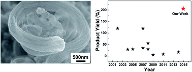
A large-scale synthesis of water-assisted single-walled carbon nanotubes (SWCNTs) was investigated over Fe–Mo/MgO catalysts by catalytic chemical vapor deposition of ethylene. Introduction of water vapor into a reactor induced super-bundle SWCNTs (SB-SWCNTs) and dramatically improved the product yield of SWCNTs from 40 to 206 wt%. By adding water vapor, the average diameter of the SB-SWCNTs was increased from 1.5 to 3.0 nm and distribution of the diameter became wider. The Raman peak intensity ratio (IG/ID) of the SWCNTs, which indicates the crystallinity and defect degree of SWCNTs, showed an almost constant value of 8 regardless of water vapor concentration. The possible growth mechanism of SB-SWCNTs was discussed.


Introduction

Carbon nanotubes (CNTs) have been extensively explored owing to their unique properties for various applications. Because of excellent electrical properties, large mechanical strength, and a high aspect ratio,1–3 single-walled CNTs (SWCNTs) have been considered an attractive material for various applications such as carbon nanotube fibers,4–6 flexible transparent films,7,8 nanoscale transistors,9 field electron emitters,10 super capacitors,11 and sensors.12

In the past two decades, the synthesis of SWCNTs has been studied using various techniques such as arc discharge,13 laser ablation,14 high-pressure CO disproportionation process,15 aerosol technique,16 thermal chemical vapor deposition (CVD),17 and catalytic CVD (CCVD).18–20 For various applications of SWCNTs, the large-scale synthesis of high-quality SWCNTs is inevitably necessary, and the price of SWCNTs has been a bottle neck for several applications. Therefore, it is still very challenging to synthesize large-scale and high-quality SWCNTs with cheap cost. In the last decade, extensive efforts have been made to increase the product yield of SWCNTs using diverse methods. Among them, introductions of water vapor or O2 gas during synthesis has been considered as an important method for the large-scale synthesis of SWCNTs.21–25 Hata et al. reported the large-scale synthesis of SWCNTs on substrates using thermal CVD.21 They claimed that adding a certain amount of water vapor greatly enhances the growth rate of vertically aligned SWCNTs. Wen et al. also showed a relatively high product yield of SWCNTs with a narrow diameter distribution by introducing a small amount of O2 gas using CCVD.24 It is well known that among various synthesis methods for SWCNTs, the CCVD method has attracted much attention because it promises a comparatively large-scale, high-purity, controllable, and cost-effective growth as compared to other methods. Therefore, the water-assisted CCVD or oxygen-assisted CCVD became a significant candidate to synthesize large-scale and low-cost SWCNTs. Nevertheless, only a few groups have reported the water-assisted CCVD method or the oxygen-assisted CCVD method for realizing the large-scale synthesis of SWCNTs.23,24 Moreover, the product yield of SWCNTs using the water-assisted CCVD or oxygen-assisted CCVD did not show significant results less than several tens percent.25 Therefore, the further study is still needed to fully understand a water-assisted growth mechanism of SWCNTs in order to realize a high product yield of SWCNTs.

Here, we demonstrate a large-scale synthesis of super-bundle SWCNTs (SB-SWCNTs) with a high yield over Fe–Mo/MgO catalysts using water-assisted CCVD. The formation and a high product yield of SB-SWCNTs are studied as a function of water vapor concentration. In addition, the possible growth mechanism of SB-SWCNTs is discussed.

Experimental

Fabrication of catalysts

The catalysts were prepared by a conventional impregnation process.20,26–28 Fe(NO3)3·9H2O (Aldrich, 99.99%) and a Mo solution (Aldrich, ICP/DCP standard solution, 9.8 mg mL−1 of Mo in H2O) were mixed with MgO powder (Kanto Chemical, BET 42 mg2 g−1) in ethanol and dried by evaporation. A molar ratio of Fe/Mo/MgO of 1[thin space (1/6-em)]:[thin space (1/6-em)]0.1[thin space (1/6-em)]:[thin space (1/6-em)]12 was used to fabricate a catalyst precursor. Then, the catalyst precursor was calcined in a tube furnace at 700 °C for 7 h in ambient air.

Synthesis of SWCNTs

Fig. 1 shows a schematic diagram of the CCVD equipment with a water vapor supplying system. For water vapor introduction, Ar gas (the carrier gas, flow rate of 50–130 sccm) was supplied to a water bubbler that was kept at room temperature. The front side of an alumina boat was opened to effectively introduce water vapor to the catalyst. The water vapor concentration was measured by a water sensor (Illinois Instrument, Model 410) that was directly connected to the exhaust line of a quartz tube reactor. The synthesis of SWCNTs was carried out in the quartz tube reactor (inner diameter: 24 mm, length: 500 mm) mounted in a tube furnace. The Fe–Mo/MgO catalyst was put into the alumina boat at the center of the reactor tube. The quartz tube reactor was purged by Ar gas while the quartz tube reactor was heated up to 750 °C. When the temperature of the quartz tube reactor reached 750 °C, water vapor and a mixture gas (total flow rate of 1000 sccm), which consisted of Ar gas, H2 gas (flow rate of 50 sccm), and C2H4 (flow rate of 35 sccm), were separately introduced into the reactor for 10 min. After finishing the SWCNT growth, the quartz tube reactor was cooled to room temperature in an Ar gas atmosphere.
image file: c5ra03000e-f1.tif
Fig. 1 Schematic diagram of CCVD equipment with a water vapor supplying system.

Characterization of SWCNTs

Scanning electron microscopy (SEM, Hitachi, S4800) and transmission electron microscopy (TEM, JEOL, JEM-2011) were used to characterize the morphology, structure, and diameter of the SWCNTs. Micro-Raman spectroscopy (Horiba, HR-800) was used to characterize the diameter, defect degree, and crystallinity of the SWCNTs. Thermogravimetric analysis (TGA, TA Instrument, Q50) was performed to understand the purity and thermal stability of the SWCNTs.

Results and discussion

Fig. 2a shows a typical SEM image of the as-grown SWCNTs without water vapor. Many entangled and randomly oriented SWCNTs are observed. Fig. 2g shows a magnified SEM image of the as-grown SWCNTs shown in Fig. 2a. The density of the SWCNTs is low and most of the SWCNTs are entangled and laid down on the support materials.20,26–28 Fig. 2b–f show SEM images of the as-grown SB-SWCNTs with water vapor concentrations of 1300–2300 ppm. The images show long and large-diameter super bundles. The diameters of the bundles are in the range of 500 nm to 2 μm, and the length is more than several hundred micrometers. Super bundles of SWCNTs are not observed when the water vapor concentration is less than 1200 ppm. Fig. 2h shows a magnified SEM image of SB-SWCNTs with a water vapor concentration of 1600 ppm. The diameters of the SB-SWCNTs are uniform and most SWCNTs are quasi-aligned along the bundle axis. It is considered that an appropriate amount of water vapor can activate the catalysts by removing amorphous carbon through oxidization. As a result, many catalysts can contribute to the growth of SWCNTs and also have a long lifetime, resulting in super growth of SWCNTs. On the other hand, without water vapor, most of the catalysts may be poisoned due to the accumulation of amorphous carbon coating.29
image file: c5ra03000e-f2.tif
Fig. 2 (a) SEM image of SWCNTs without water vapor. (b–f) SEM images of SB-SWCNTs with water vapor concentrations of 1300, 1600, 1800, 2100, and 2300 ppm, respectively. (g) High-magnification SEM image of SWCNTs without water vapor. (h) High-magnification SEM image of SB-SWCNTs with a water vapor concentration of 1600 ppm.

Raman spectra were used to analyze the diameter, crystallinity, and defect degree of CNTs. Fig. 3a shows the Raman spectra of the as-grown SB-SWCNTs according to the water vapor concentration. The Raman spectra are characterized by three main peaks, the G-band (related to C–C stretching within the graphene plane, ∼1590 cm−1), the D-band (originating from the disordered lattice at the graphene sheets, ∼1300–1350 cm−1), and the radial breathing mode (RBM). All as-grown CNT samples show clear peaks in the RBM range and in the second-order D band, which provides clear evidence of SWCNTs. The peak intensity ratio (IG/ID) is generally used to evaluate the quality of CNTs. The IG/ID ratio of the as-grown SB-SWCNTs shows a constant value of ∼8 regardless of water vapor concentration, as shown in Fig. 3b. This means that the water vapor mainly doesn't affect the crystallinity or the defect degree of the SB-SWCNTs.


image file: c5ra03000e-f3.tif
Fig. 3 (a) Raman spectra of as-grown SB-SWCNTs according to the water vapor concentration. (b) IG/ID ratios of as-grown SB-SWCNTs as a function of the water vapor concentration.

We investigated RBM peaks of SB-SWCNTs in order to calculate diameters of individual SWCNTs. Raman analysis for RBM peaks was performed using excitation laser wavelengths of 488 and 514.5 nm. Fig. 4 shows details of RBM peaks of SWCNTs without water vapor and with a water vapor concentration of 1600 ppm.


image file: c5ra03000e-f4.tif
Fig. 4 RBM peaks of SWCNT samples obtained using two excitation laser wavelengths (λex): (a) 488 and (b) 514.5 nm.

It is well known that the frequency range at the RBM is strongly dependent on the diameters of SWCNTs, and the smaller wavenumber of a peak means a larger diameter of SWCNTs. In general, the expression, d (nm) = 248/w (cm−1), can be used to calculate the diameters of SWCNTs, where d is the diameter of SWCNTs and w is the wavenumber of peaks.30 Fig. 4 shows RBM peaks at 92.78, 198.16, 221.83 cm−1 using λex = 488 nm, and at 116.28, 177.38, 201.38 cm−1 using λex = 514.5 nm. The peaks are correspondent to diameters of 2.67, 1.25, 1.10, 2.13, 1.40 and 1.23 nm, respectively. The SB-SWCNTs show that the intensity of RBM peaks are increased regardless of excitation laser wavelength at a low-frequency range below 150 cm−1, whereas RBM peaks are diminished or disappeared at a high-frequency range between 150 and 300 cm−1. This means that the diameters of the SB-SWCNTs increased with increasing water vapor concentration during the reaction.

TGA and derivative thermogravimetry (DTG) were carried out in order to investigate the purity and thermal stability of the as-grown SWCNTs. Fig. 5 shows the TGA and DTG curves of the as-grown SB-SWCNTs according to the water vapor concentration. As shown in Fig. 5a, the carbon content of the SWCNTs without water vapor was approximately 30 wt%, but the carbon content of the SB-SWCNTs increased dramatically, reaching 75 wt% at the water vapor concentration of 1600 ppm. This value is approximately 2.5 times higher than that of SWCNTs without water vapor. However, once the water vapor concentration exceeded 1600 ppm, the carbon content decreased due to the enhanced oxidation effect. The maximum carbon content of SB-SWCNTs was much higher than that reported in previous works, in which the carbon content increased from 15 to 21 wt% by adding water vapor23 and from 24 to 28.6 wt% by adding O2 gas.24 Fig. 5b shows that the DTG peaks of SB-SWCNTs with water vapor have a slight shift towards higher temperatures. The high-intensity peaks with narrow width indicate that the SB-SWCNTs had high purity and high thermal stability, and the product yield of SB-SWCNTs was the highest at the water vapor concentration of 1600 ppm. The DTG curves show that the SWCNTs without water vapor decomposed at a temperature of 550 °C, whereas the SB-SWCNTs had a maximum decomposition temperature of 600 °C. It is well known that small-diameter SWCNTs are more easily oxidized at lower temperatures than large-diameter SWCNTs.31 Based on the Raman spectra results, the crystallinities of SWCNTs and SB-SWCNTs are similar regardless water vapor concentration. Therefore, the DGT result indicates that the diameters of the SB-SWCNTs were larger than those of SWCNTs without water vapor.


image file: c5ra03000e-f5.tif
Fig. 5 (a) TGA and (b) DTG curves of as-grown SB-SWCNTs according to the water vapor concentration.

TEM observation was conducted in order to evaluate the morphology, structure, and diameter of the SWCNTs. Fig. 6a and b show typical TEM images of the as-grown SWCNTs without water vapor, which mainly consisted of small bundles with diameters in the range of 5–20 nm. Occasionally, a few isolated SWCNTs were observed, as shown in Fig. 6b. The isolated SWCNTs normally exhibited larger diameters (1.8–2.5 nm) than the SWCNTs within the small bundles (1.0–1.5 nm). Fig. 6c and d show TEM images of SB-SWCNTs with a water vapor concentration of 1600 ppm, indicating an individual super bundle with highly densely packed SWCNTs. The diameter of the super bundle is in the range of several hundred nanometers. Fig. 6e and f show high-magnification TEM images of SB-SWCNTs that have large diameters in the range of 2.2–4.0 nm. All SWCNTs within the super bundle show a clean surface without amorphous carbon material.


image file: c5ra03000e-f6.tif
Fig. 6 (a) TEM image of SWCNTs without water vapor. (b) High-magnification TEM image of SWCNTs without water vapor. (c and d) TEM images of SB-SWCNTs with a water vapor concentration of 1600 ppm. (e and f) High-magnification TEM images of SB-SWCNTs with a water vapor concentration of 1600 ppm.

Fig. 7 shows a histogram of the diameter distributions of SWCNTs according to the water vapor concentration. The diameters were obtained from TEM images using 52 individual SWCNTs. A Gaussian curve was used for determination of the distributions of average diameter, standard deviation (SD), and full-width at half-maximum (FWHM). By adding water vapor, the diameters shifted towards large sizes with wider distributions. The average diameter increased from 1.5 to 3.0 nm, the SD increased from 0.19 to 0.41, and the FWHM increased from 0.45 to 0.97. It is thus confirmed that the TEM observation of the diameters of the SWCNTs agree with the Raman RBM results.


image file: c5ra03000e-f7.tif
Fig. 7 Diameter distribution of as-grown SWCNTs according to the water vapor concentration.

In this work, we evaluated the product yield (ratio of the mass of carbon nanotubes to the mass of catalyst) using the following formula:

 
image file: c5ra03000e-t1.tif(1)
where Massproduct is the weight of the final product, including catalysts and carbon, and Masscatalyst is the weight of the catalysts. Fig. 8a shows the product yield of the as-grown SWCNTs as a function of the water vapor concentration. The product yield of SWCNTs without water vapor was 40 wt%. It dramatically increased to 206 wt% at the water vapor concentration of 1600 ppm, a value that is five times larger than that of SWCNTs without water vapor. Interestingly, the product yield gradually decreased with water vapor concentrations over 1600 ppm. This result indicates that higher water vapor concentration may induce the active oxidation of catalysts resulting in increasing the poisoning effect of catalysts. Fig. 8b compares the product yields of the SWCNTs. The product yield of our SB-SWCNTs was much higher than that of SWCNTs previously reported.23,25,27,32–38 The high product yield of SB-SWCNTs may be attributed to the high density of catalyst nanoparticles with a suitable size and also the long lifetime of catalyst nanoparticles with water vapor.


image file: c5ra03000e-f8.tif
Fig. 8 (a) Product yield of as-grown SB-SWCNTs as a function of the water vapor concentration. (b) Comparison of the product yield of SWCNTs.23,25,27,32–38

Fig. 9 presents a schematic diagram of the possible growth mechanism of SB-SWCNTs using water-assisted CCVD.39 During calcination at 700 °C for 7 h in ambient air, O2 molecules adsorbed on catalyst nanoparticles diffuse into the nanoparticles, which then oxidize the catalyst nanoparticles on the MgO support material. Consequently, during the growth process, the oxidized catalyst nanoparticles are reduced in the H2-rich environment, and some of them are agglomerated into larger particles on the MgO support material, which is known as the “Ostwald ripening” phenomenon.40 As a result, both the average diameter and the diameter distributions of the catalyst nanoparticles increase, whereas the density of the catalyst nanoparticles decreases. Some ripened catalyst nanoparticles lose their catalyst activity due to encapsulation by an amorphous carbon coating, so-called catalyst poisoning, resulting in unsuccessful CNT growth. Therefore, only a few catalyst nanoparticles with small diameters are available to grow SWCNTs. On the other hand, by adding water vapor, the surface of the catalyst nanoparticles can be kept active because amorphous carbons are easily removed from the catalyst nanoparticles, extending the lifetime of catalyst nanoparticles during growth of SWCNTs. The water vapor can also react with the MgO support materials and induce the formation of hydroxyl-terminated groups on the surface of the MgO support materials.40,41 Surface-bound hydroxyl groups retard the effect of Ostwald ripening and induce a uniform size of catalyst nanoparticles with high density. Therefore, the density of active catalyst nanoparticles is significantly increased by adding water vapor. For the synthesis of SB-SWCNTs, high density of active catalyst nanoparticle with a suitable size is inevitably necessary, and also the active catalyst nanoparticles have to keep a long lifetime.


image file: c5ra03000e-f9.tif
Fig. 9 Schematic diagram of the growth mechanism of SB-SWCNTs using water-assisted CCVD.

Fig. 10a and b show bright-field (BF) and dark-field (DF) TEM images, respectively, of catalyst nanoparticles after thermal annealing in H2/Ar gas for 90 s without water vapor. The sizes of the catalyst nanoparticles are non-uniform, and most of them have large diameters over 8 nm, which are too large to initiate the nucleation of SWCNTs. Only a few catalyst nanoparticles have relatively small diameters of less than 5 nm. This result means that most of catalyst nanoparticles are agglomerated during thermal annealing without water vapor, so called ripening behavior.40 Fig. 10c and d show BF and DF TEM images, respectively, of catalyst nanoparticles after thermal annealing in H2/Ar gas for 90 s with a water vapor concentration of 1600 ppm. The uniform-sized catalyst nanoparticles (4–6 nm) are well distributed on the surface of the MgO support material. It is difficult to find agglomeration of catalyst nanoparticles.


image file: c5ra03000e-f10.tif
Fig. 10 (a) Bright-field and (b) dark-field TEM images of catalyst nanoparticles on the MgO support material after thermal annealing in H2/Ar gas for 90 s without water vapor. (c) Bright-field and (d) dark-field TEM images of catalyst nanoparticles on the MgO support material after thermal annealing in H2/Ar gas for 90 s with a water vapor concentration of 1600 ppm.

Fig. 11a shows an SEM image of SB-SWCNTs grown on the plate-shaped MgO support material (white arrow), evidence of bi-directional growth (black arrows). Fig. 11b shows a TEM image of SB-SWCNTs grown on the plate-shaped MgO support material. The black plate is the MgO support material (white arrow). In this work, the Fe–Mo/MgO catalysts were fabricated by an impregnation method, in which the support materials were not spherical but rather plate-shaped. Therefore, catalyst nanoparticles can be formed on both sides of the plate-shaped MgO support materials. As a result, we were able to produce a high density of SB-SWCNTs with bi-directional growth on the surface of MgO support materials.


image file: c5ra03000e-f11.tif
Fig. 11 (a) SEM image of SB-SWCNTs grown on the plate-shaped MgO support material (white arrow), indicating bi-directional growth (black arrows). (b) TEM image of SB-SWCNTs grown on the plate-shaped MgO support material. The black plate is the MgO support material (white arrow).

Conclusion

We demonstrated the synthesis of SB-SWCNTs using water-assisted CCVD of ethylene over Fe–Mo/MgO catalysts. By introducing water vapor into the reactor, it was possible to enhance catalyst activity and also to prevent the coalescence of catalytic particles. The synthesis of SB-SWCNTs is mainly attributed to high density and long lifetime of active catalysts due to the water vapor effect. By adding water vapor, the product yield of SB-SWCNTs was dramatically improved (206 wt%) as compared to that of SWCNTs without water vapor (40 wt%). The average diameter of the SB-SWCNTs increased from 1.5 to 3.0 nm and the distribution of diameters was wider. The IG/ID ratio of SWCNTs, which indicates the crystallinity and defect degree of SWCNTs, showed an almost constant value of 8 regardless of the water vapor concentration. The SB-SWCNTs follow a base growth mechanism and indicate bi-directional growth at several micrometer plate-shaped support materials.

Acknowledgements

This work was supported by World Class University (WCU, R32-2008-000-10082-0) Project and International Cooperation of Science &Technology (KICOS, 2009-00299) Project through the National Research Foundation of Korea funded by the Ministry of Education, Science and Technology. It was also supported by the Korea Basic Science Institute.

Notes and references

  1. S. Iijima and T. Ichihashi, Nature, 1993, 363, 603–605 CrossRef CAS.
  2. M. M. J. Treacy, T. W. Ebbesen and J. M. Gibson, Nature, 1996, 381, 678–680 CrossRef CAS.
  3. T. W. Ebbesen, H. J. Lezec, H. Hiura, J. W. Bennett, H. F. Ghaemi and T. Thio, Nature, 1996, 382, 54–56 CrossRef CAS.
  4. N. Behabtu, C. C. Young, D. E. Tsentalovich, O. Kleinerman, X. Wang, A. W. K. Ma, E. A. Bengio, R. F. ter Waarbeek, J. J. de Jong, R. E. Hoogerwerf, S. B. Fairchild, J. B. Ferguson, B. Maruyama, J. Kono, Y. Talmon, Y. Cohen, M. J. Otto and M. Pasquali, Science, 2013, 339, 182–186 CrossRef CAS PubMed.
  5. C. Jiang, A. Saha, C. Xiang, C. C. Young, J. M. Tour, M. Pasquali and A. A. Martí, ACS Nano, 2013, 7, 4503–4510 CrossRef CAS PubMed.
  6. C. Jiang, A. Saha, C. C. Young, D. P. Hashim, C. E. Ramirez, P. M. Ajayan, M. Pasquali and A. A. Martí, ACS Nano, 2014, 8, 9107–9112 CrossRef CAS PubMed.
  7. A. Saha, S. Ghosh, R. B. Weisman and A. A. Martí, ACS Nano, 2012, 6, 5727–5734 CrossRef CAS PubMed.
  8. A. Saha, C. Jiang and A. A. Martí, Carbon, 2014, 79, 1–18 CrossRef CAS PubMed.
  9. K. Yang, L. Huang, Y. Liu, C. Xu, Y. Bai, S. Huang, Z. Yang, Z. Xu and H. Wang, RSC Adv., 2013, 3, 23658–23663 RSC.
  10. Y. Saito and S. Uemura, Carbon, 2000, 38, 169–182 CrossRef CAS.
  11. C. G. Liu, M. Liu, F. Li and H. M. Cheng, Appl. Phys. Lett., 2008, 92, 143108 CrossRef PubMed.
  12. A. Modi, N. Koratkar, E. Lass, B. Q. Wei and P. M. Ajayan, Nature, 2003, 424, 171–174 CrossRef CAS PubMed.
  13. C. Journet, W. K. Maser, P. Bernier, A. Loiseau, M. L. delaChapelle, S. Lefrant, P. Deniard, R. Lee and J. E. Fischer, Nature, 1997, 388, 756–758 CrossRef CAS PubMed.
  14. A. Thess, R. Lee, P. Nikolaev, H. J. Dai, P. Petit, J. Robert, C. H. Xu, Y. H. Lee, S. G. Kim, A. G. Rinzler, D. T. Colbert, G. E. Scuseria, D. Tomanek, J. E. Fischer and R. E. Smalley, Science, 1996, 273, 483–487 CAS.
  15. P. Nikolaev, M. J. Bronikowski, R. K. Bradley, F. Rohmund, D. T. Colbert, K. A. Smith and R. E. Smalley, Chem. Phys. Lett., 1999, 313, 91–97 CrossRef CAS.
  16. A. G. Nasibulin, A. Moisala, D. P. Brown, H. Jiang and E. I. Kauppinen, Chem. Phys. Lett., 2005, 402, 227–232 CrossRef CAS PubMed.
  17. J. Kong, H. T. Soh, A. M. Cassell, C. F. Quate and H. J. Dai, Nature, 1998, 395, 878–881 CrossRef CAS PubMed.
  18. K. Mukhopadhyay, A. Koshio, T. Sugai, N. Tanaka, H. Shinohara, Z. Konya and J. B. Nagy, Chem. Phys. Lett., 1999, 303, 117–124 CrossRef CAS.
  19. S. Maruyama, R. Kojima, Y. Miyauchi, S. Chiashi and M. Kohno, Chem. Phys. Lett., 2002, 360, 229–234 CrossRef CAS.
  20. S. C. Lyu, B. C. Liu, S. H. Lee, C. Y. Park, H. K. Kang, C. W. Yang and C. J. Lee, J. Phys. Chem. B, 2004, 108, 1613–1616 CrossRef CAS.
  21. K. Hata, D. N. Futaba, K. Mizuno, T. Namai, M. Yumura and S. Iijima, Science, 2004, 306, 1362–1364 CrossRef CAS PubMed.
  22. H. Ago, N. Uehara, N. Yoshihara, M. Tsuji, M. Yumura, N. Tomonaga and T. Setoguchi, Carbon, 2006, 44, 2912–2918 CrossRef CAS PubMed.
  23. N. Yoshihara, H. Ago and M. Tsuji, J. Phys. Chem. C, 2007, 111, 11577–11582 CAS.
  24. Q. Wen, W. Z. Qian, F. Wei and G. Q. Ning, Nanotechnology, 2007, 18, 215610 CrossRef.
  25. F. Ren, S. A. Kanaan, M. M. Majewska, G. D. Keskar, S. Azoz, H. Wang, X. Wang, G. L. Haller, Y. Chen and L. D. Pfefferle, J. Catal., 2014, 309, 419–427 CrossRef CAS PubMed.
  26. B. C. Liu, S. C. Lyu, T. J. Lee, S. K. Choi, S. J. Eum, C. W. Yang, C. Y. Park and C. J. Lee, Chem. Phys. Lett., 2003, 373, 475–479 CrossRef CAS.
  27. B. C. Liu, S. C. Lyu, S. I. Jung, H. K. Kang, C. W. Yang, J. W. Park, C. Y. Park and C. J. Lee, Chem. Phys. Lett., 2004, 383, 104–108 CrossRef CAS PubMed.
  28. H. Zhang, D. H. Shin, H. S. Lee and C. J. Lee, J. Phys. Chem. C, 2007, 111, 12954–12959 CAS.
  29. T. Yamada, A. Maigne, M. Yudasaka, K. Mizuno, D. N. Futaba, M. Yumura, S. Iijima and K. Hata, Nano Lett., 2008, 8, 4288–4292 CrossRef CAS PubMed.
  30. A. Jorio, R. Saito, J. H. Hafner, C. M. Lieber, M. Hunter, T. McClure, G. Dresselhaus and M. S. Dresselhaus, Phys. Rev. Lett., 2001, 86, 1118–1121 CrossRef CAS.
  31. S. Nagasawa, M. Yudasaka, K. Hirahara, T. Ichihashi and S. Iijima, Chem. Phys. Lett., 2000, 328, 374–380 CrossRef CAS.
  32. Q. W. Li, H. Yan, Y. Cheng, J. Zhang and Z. F. Liu, J. Mater. Chem., 2002, 12, 1179–1183 RSC.
  33. M. Kumar and Y. Ando, Carbon, 2005, 43, 533–540 CrossRef CAS PubMed.
  34. Z. Q. Niu and Y. Fang, Superlattices Microstruct., 2007, 41, 62–70 CrossRef CAS PubMed.
  35. A. R. Biris, Z. R. Li, E. Dervishi, L. P. Dan, Y. Xu, V. Saini, F. Watanabe and A. S. Biris, Phys. Lett. A, 2008, 372, 3051–3057 CrossRef CAS PubMed.
  36. Y. Xu, Z. R. Li, E. Dervishi, V. Saini, J. B. Cui, A. R. Biris, D. Lupu and A. S. Biris, J. Mater. Chem., 2008, 18, 5738–5745 RSC.
  37. J. Q. Nie, W. Z. Qian, Q. Zhang, Q. Wen and F. Wei, J. Phys. Chem. C, 2009, 113, 20178–20183 CAS.
  38. J. Q. Nie, Q. Zhang, M. Q. Zhao, J. Q. Huang, Q. A. Wen, Y. Cui, W. Z. Qian and F. Wei, Carbon, 2011, 49, 1568–1580 CrossRef CAS PubMed.
  39. G. Q. Ning, F. Wei, Q. Wen, G. H. Luo, Y. Wang and Y. Jin, J. Phys. Chem. B, 2006, 110, 1201–1205 CrossRef CAS PubMed.
  40. P. B. Amama, C. L. Pint, L. McJilton, S. M. Kim, E. A. Stach, P. T. Murray, R. H. Hauge and B. Maruyama, Nano Lett., 2009, 9, 44–49 CrossRef CAS PubMed.
  41. C. L. Pint, S. T. Pheasant, A. N. G. Parra-Vasquez, C. Horton, Y. Q. Xu and R. H. Hauge, J. Phys. Chem. C, 2009, 113, 4125–4133 CAS.

This journal is © The Royal Society of Chemistry 2015
Click here to see how this site uses Cookies. View our privacy policy here.