
AB2 Y-shaped miktoarm star conductive polyaniline-modified poly(ethylene glycol) and its electrospun nanofiber blend with poly(ε-caprolactone)
Bakhshali Massoumia,
Somayeh Davtalaba,
Mehdi Jaymand*b and
Ali Akbar Entezamic
aDepartment of Chemistry, Payame Noor University, P.O. BOX: 19395-3697, Tehran, Islamic Republic of Iran
bResearch Center for Pharmaceutical Nanotechnology, Tabriz University of Medical Sciences, P.O. Box: 51656-65811, Tabriz, Islamic Republic of Iran. E-mail: m_jaymand@yahoo.com; m.jaymand@gmail.com; jaymandm@tbzmed.ac.ir; Fax: +98-41-33367929; Tel: +98-41-33367914
cLaboratory of Polymer, Faculty of Chemistry, Tabriz University, P.O. BOX: 51666-16471, Tabriz, Islamic Republic of Iran
First published on 15th April 2015
Abstract
This paper describes the synthesis and characterization of novel type AB2 Y-shaped miktoarm star conductive polyaniline-modified poly(ethylene glycol) [PEG-b-(PANI)2], and preparation of its electrospun nanofiber blend with poly(ε-caprolactone) [PEG-b-(PANI)2/PCL]. The chemical structures of all samples as representatives were characterized by means of Fourier transform infrared (FTIR), and 1H nuclear magnetic resonance (NMR) spectroscopies. The molecular weights of PANI segment(s), and miktoarm star conductive PEG-b-(PANI)2 were found to be 3720, and 5847, respectively, from 1H NMR spectroscopy. Moreover, electrical conductivities, electroactivities, thermal behaviors, morphologies, and compositions of the synthesized samples were studied. The conductivity and electroactivity measurements showed that PEG-b-(PANI)2 and PEG-b-(PANI)2/PCL electrospun blend nanofibers have lower electrical conductivity and electroactivity than those of the pure PANI. However, the lower electrical conductivity and electroactivity levels in these materials can be improved at the price of solubility, processability, and biocompatibility. Field emission scanning electron microscopy (FE-SEM) images showed that the PEG-b-(PANI)2/PCL electrospun nanofibers have a single phase, indicating good interactions between the blend components. The average diameters of these fibers were in the size range of 70 ± 10 nm, and there was no formation of beaded structures in comparison with electrospun fibers of pure PCL. As results, we predicted the synthesized PEG-b-(PANI)2 and PEG-b-(PANI)2/PCL can be used in the biomedical fields such as in conductive scaffolds to promote neurite outgrowth, and nerve regeneration.
1. Introduction
Since the discovery of doped polyacetylene as a conductive polymer (CP) in 1977, these types of polymers have stimulated a great deal of research effort on the basis of their importance in basic scientific research and potential industrial applications, due to their unique semiconducting and optoelectronic properties.1–5 The most commonly used conductive polymers are polythiophene (PTh), polypyrrole (PPy), polyaniline (PANI), and their derivatives. Among them PANI has many attractive properties such as low-cost synthesis (via electrochemical or chemical oxidation polymerization), chemical and electronic properties, tunable electroactivity, environmental and thermal stability, and many more.1,6–9 Moreover, PANI has a wide range of commercial and technological applications, such as secondary batteries,10 solar cells,11 bio/chemical sensors,12 corrosion devices,13 organic light emitting diodes (OLEDs),14 electro-magnetic interference (EMI) shielding,15 biomedical applications,16 and many more.However, similar to other π-conjugated polymers the main drawback of polyaniline is the lack of solubility, which explains its limited processability, in part due to its rigid backbone. Thus, modification of polyaniline is necessary to expand its applications, and has been the subject of much investigation.17–20 In order to overcome these major deficiencies, well established techniques are: (1) doping of PANI with functionalized protonic organic acids (e.g., dodecylbenzene sulfonic acid, and camphorsulfonic acid);21 (2) preparation of PANI composites with thermoplastic polymers;22 (3) monomer modification (e.g., rings and N-substituted anilines);23 and (4) incorporation of polar functional groups, polymeric chains or long and flexible alkyl chains in the PANI backbone.24
In addition, a relatively novel achievement with PANI and its derivatives is their tissue engineering performance, in part due to its conductivity, reversible oxidation, redox stability, biocompatibility, hydrophobicity (40–70° water contact angle promotes cell adhesion), three-dimensional geometry, and surface topography.25 PANI in purified form exhibits relatively good biocompatibility, which is further enhanced by blending with other polymers.26 In this respect, poly(ethylene oxide) (PEO),27 poly(ethylene glycol) (PEG),28 chitosan,29 gelatin,30 and poly(ε-caprolactone) (PCL)31 can be used for enhanced biocompatibility of the PANI. An efficient and versatile strategy to prepare biocompatible nanofiber blends of PANI is electrospinning with biocompatible polymers.32–35 For example, the preparation of electrospun conductive nanofibers consisting PCL and PANI or its copolymers has been extensively studied by the Entezami group.36,37 They concluded that the prepared nanofibers could be potential candidates for tissue engineering due to their electroactivity, and biocompatibility.
We report here our preliminary investigations on the synthesis, and characterization of AB2 Y-shaped miktoarm star conductive polyaniline-modified poly(ethylene glycol), and its electrospun nanofibers blend with poly(ε-caprolactone). For this purpose, the poly(ethylene glycol) end-caped diol was functionalized with p-antranilic acid to produce phenylamine-functionalized poly(ethylene glycol) AB2 macromonomer (PhAPEGM). Afterwards, PANI was grafted onto functionalized poly(ethylene glycol) via a chemical oxidation polymerization method. The solutions of synthesized AB2 Y-shaped miktoarm star PEG-b-(PANI)2 copolymer, and poly(ε-caprolactone) was electrospun to produce uniform, conductive, and biocompatible nanofibers.
2. Experimental
2.1. Materials
Poly(ethylene glycol) monomethylether (Mn = 2000), and poly(ε-caprolactone) (Mn = 70![[thin space (1/6-em)]](https://www.rsc.org/images/entities/char_2009.gif) 000–90000), sodium hydroxide, p-toluene sulfonic acid (p-TSA), camphorsulfonic acid (CSA), p-antranilic acid (4-aminobenzoic acid), and sodium hydride (NaH) were purchased from Merck (Darmstadt, Germany), and were used as received. Epichlorohydrin (Merck) was dried by calcium hydride (CaH2), and distilled twice under reduced pressure before use. Toluene and xylene (Merck) were dried by refluxing over sodium, and distilled under argon prior to use. Aniline monomer (Merck) was distilled twice under reduced pressure before use. Ammonium peroxydisulfate (APS) from Merck was re-crystallized at room temperature from ethanol–water. All other reagents were purchased from Merck and purified according to the standard methods.
000–90000), sodium hydroxide, p-toluene sulfonic acid (p-TSA), camphorsulfonic acid (CSA), p-antranilic acid (4-aminobenzoic acid), and sodium hydride (NaH) were purchased from Merck (Darmstadt, Germany), and were used as received. Epichlorohydrin (Merck) was dried by calcium hydride (CaH2), and distilled twice under reduced pressure before use. Toluene and xylene (Merck) were dried by refluxing over sodium, and distilled under argon prior to use. Aniline monomer (Merck) was distilled twice under reduced pressure before use. Ammonium peroxydisulfate (APS) from Merck was re-crystallized at room temperature from ethanol–water. All other reagents were purchased from Merck and purified according to the standard methods.
2.2. Synthesis of α-methoxy-ω-epoxy-poly(ethylene glycol)
In a three-neck round-bottom flask equipped with a condenser, dropping funnel, gas inlet/outlet, and a magnetic stirrer, 8 g (4 mmol) of poly(ethylene glycol) monomethylether was dissolved in anhydrous toluene (50 ml), and added under argon atmosphere to 144 mg (6 mmol) of hexane-washed NaH (from 60% suspension in oil). The mixture was stirred for about 1 hour at room temperature, and 0.6 ml (7.2 mmol) of dried epichlorohydrin was then added under an argon atmosphere, and refluxed for about 6 hours at 40 °C. The reaction was terminated by pouring the contents of the flask into a large amount of diethyl ether. The product was filtered, and dried in vacuum at room temperature to afford ω-epoxy terminated poly(ethylene glycol) methylether.2.3. Synthesis of poly(ethylene glycol) end-caped diol (PEG-diol)
In a round-bottom flask equipped with a condenser, and a magnetic stirrer, α-methoxy-ω-epoxy-poly(ethylene glycol) (6.44 g, 3.1 mmol) was dissolved in sodium hydroxide solution (50 ml; 1 M), and the solution was stirred for about 20 hours at 60 °C. At the end of this period, the mixture was frozen and lyophilized. The crude product was purified by dialyzing in distilled water (one liter) using 1000 molecular weight cut-off dialyzed bag. The product was filtered, and dried in vacuum at room temperature.2.4. Synthesis of phenylamine-functionalized poly(ethylene glycol) AB2 macromonomer (PhAPEGM)
In a three-neck round-bottom flask equipped with a dean-stark trap, gas inlet/outlet, and a magnetic stirrer, PEG-diol (4.7 g, 2.26 mmol), and p-antranilic acid (1 g, 7.2 mmol) were dissolved in anhydrous xylene (60 ml). A catalytic amount of p-TSA (0.1 g, 0.55 mmol) was added to the reaction mixture, and the mixture was de-aerated by bubbling highly pure argon for 10 minutes. At the end of this period, the reaction mixture was heated up to 140 °C for about 5 hours. The water of reaction was removed as an azeotrope until no more water was formed. It could mean that the reaction had gone to completion. Then, the reaction flask was rapidly cooled to room temperature by ice water bath. The product was precipitated by adding diethyl ether. The crude product was extracted with chloroform for three times, in order to remove un-reacted p-antranilic acid. It is important to note that the p-antranilic acid is not soluble in chloroform, while phenylamine-functionalized poly(ethylene glycol) is soluble in this solvent. The polymer solution was filtered, precipitated into large amount of diethyl ether, and dried in vacuum at room temperature.2.5. Synthesis of Y-shaped miktoarm star poly(ethylene glycol)-b-(polyaniline)2 [PEG-b-(PANI)2] copolymer
A 250 ml round-bottom flask containing distilled water (50 ml), and phenylamine-functionalized poly(ethylene glycol) AB2 macromonomer (0.3 g) was equipped with a mechanical stirrer. After stirring for about 1 hour, 1 g (10.7 mmol) of aniline, and camphorsulfonic acid (4.65 g, 20 mmol) were added to the solution. The mixture was vigorously stirred for another 1 hour, and temperature was reduced to 0 °C. In a separate container, (2.28 g, 10 mmol) of APS was dissolved in distilled water (30 ml). The oxidant solution was slowly added at a rate of 5 ml min−1 to the above mentioned mixture. The reaction mixture was stirred for about 8 hours at 0 °C, and at the end of this period the reaction was terminated by pouring the content of the flask into a large amount of diethyl ether. The resultant product was filtered, and dried in vacuum at room temperature. The crude product was extracted with tetrahydrofuran (THF) in a Soxhlet apparatus for 24 hours, in order to remove any homo-polyaniline chains. The synthesized poly(ethylene glycol)-b-(polyaniline)2 is soluble in THF (Table 2), while homo-polyaniline is not soluble in THF. The polymer solution was filtered, precipitated into excess diethyl ether, and dried in vacuum at room temperature.2.6. Synthesis of homo-polyaniline
The homo-polyaniline was synthesized by a chemical oxidation polymerization method as follows. A 250 ml round-bottom flask was charged with distilled water (50 ml), aniline (1 g, 10.7 mmol), and camphorsulfonic acid (4.65 g, 20 mmol). The mixture was vigorously stirred and temperature was reduced to 0 °C. In a separate container, (2.28 g, 10 mmol) of oxidant (APS) was dissolved in distilled water (30 ml). The oxidant solution was slowly added at a rate of 5 ml min−1 to the reaction mixture. The mixture was stirred for about 8 hours at 0 °C, and then the reaction was terminated by pouring the content of the flask into a large amount of methanol. The resultant product was filtered, washed with methanol several times, and dried in vacuum at room temperature.2.7. Electrospinning of poly(ethylene glycol)-b-(polyaniline)2/poly(ε-caprolactone), and pure poly(ε-caprolactone)
The poly(ethylene glycol)-b-(polyaniline)2/poly(ε-caprolactone), and pure poly(ε-caprolactone) nanofibers were prepared by a electrospinning apparatus was equipped with a high voltage power supply (Gamma High Voltage Research E8-50P, Ormond Beach, FL, USA). Immediately before electrospinning, emeraldine base form of poly(ethylene glycol)-b-(polyaniline)2 (0.2 g), and camforsulfonic acid (0.1 g) were dissolved in 2-chloroethanol (10 ml) with stirring at room temperature for about 1 hour, followed by filtering through a regular qualitative filter paper (Whatman). In a separate container, 0.2 g of poly(ε-caprolactone) was dissolved in mixture of chloroform/2-chloroethanol (2/1; v/v) (10 ml) with stirring at room temperature for about 1 hour. Thus, the concentration of the CSA-doped poly(ethylene glycol)-b-(polyaniline)2 solution was 3% (w/v), and pure poly(ε-caprolactone) solution was 2% (w/v). Samples for electrospinning were then prepared by mixing two solutions at volume ratios of CSA-doped poly(ethylene glycol)-b-(polyaniline)2 to poly(ε-caprolactone) at 30:70. The polymers solutions were added to a 10 ml syringe with a 23G hypodermic needle used as the nozzle. The flow rate of the polymer solution was controlled with a precision pump (JZB 1800D double channel syringe pump, China) to maintain a steady flow from the capillary outlet. The solution was injected at the rate of 0.5 ml h−1, and the applied voltage was set to 20 kV. The static collector was wrapped with aluminum foil, and located at a fixed working distance of 15 cm from the needle tip. After fiber deposition, the fiber mats was dried in vacuum at room temperature. The pure poly(ε-caprolactone) nanofibers was prepared in the same condition.
2.8. Electrochemical system
The electrochemical measurements were carried out using Auto-Lab equipment (ECO Chemie, Utrecht, The Netherlands) equipped with a three-electrode cell assembly. The system was run on a PC using NOVA 1.8 and FRA software. A glassy carbon microelectrode (with a surface area of 0.03 cm2), a platinum rod, and Ag/AgCl (3 M in KCl) were used as working, counter, and reference electrodes, respectively (all electrodes from metrohm). All potentials applied between working and counter electrodes, so the final current measured between working and reference electrodes. The surface of the working electrode was polished with emery paper followed by 0.5 μm alumina, and then washed with acetone. The working electrode coated with the synthesized sample was prepared by casting. The electrochemical measurements were accomplished in the camphorsulfonic acid (0.5 mol l−1) by applying a sequential linear potential scan rate of 25–225 mV s−1 between −0.2 and 1.0 V versus the Ag/AgCl electrode. All experimental solutions were de-aerated by bubbling highly pure argon for 10 minutes, and an argon atmosphere was kept over the solutions during the measurements.2.9. Characterization
Fourier transform infrared (FTIR) spectra of the samples were recorded on a Shimadzu 8101M FTIR (Shimadzu, Kyoto, Japan). The samples were prepared by grinding the dry powders with potassium bromide (KBr), and compressing the mixture into disks. The spectra were recorded at room temperature. 1H nuclear magnetic resonance (NMR) spectra were recorded at 25 °C using an FT-NMR (400 MHz) Bruker spectrometer (Bruker, Ettlingen, Germany). The sample for NMR spectroscopy was prepared by dissolving about 10 mg of samples in 1 ml of deuterated chloroform (CDCl3), and chemical shifts were reported in ppm units with tetramethylsilane as internal standard. Thermal properties of the samples were examined by thermogravimetric analyzer (TGA-PL STA 1640 equipment (Polymer Laboratories, Shropshire, UK)). The TGA experiments were conducted under nitrogen atmosphere in a temperature range of 25–750 °C with heating rate of 10 °C min−1. The field emission scanning electron microscope (FE-SEM) type 1430 VP (LEO Electron Microscopy Ltd, Cambridge, UK) was applied to determine the morphologies of the synthesized samples. Electrochemical experiments were conducted using Auto-Lab PGSTA T302N. The electrochemical cell contained five openings: three of them were used for the electrodes, and two for argon bubbling in the solutions during all experiments. The four-probe technique (Azar Electrode, Urmia, Iran) was used to measure the conductivity of the synthesized samples at room temperature.3. Results and discussion
In recent years a great deal of research effort has focused on the development of biocompatible conductive polymers for biomedical applications. Nevertheless, this field is still growing and many issues remain to be answered.38,39 As illustrated in Scheme 1, this study aim is synthesis of a AB2 Y-shaped miktoarm star conductive polyaniline-modified poly(ethylene glycol), and preparation of its electrospun nanofibers blend with poly(ε-caprolactone). It would be expected that the prepared nanofibers could find applications in biological fields such as tissue engineering, in part due to its biocompatibility, and conductivity.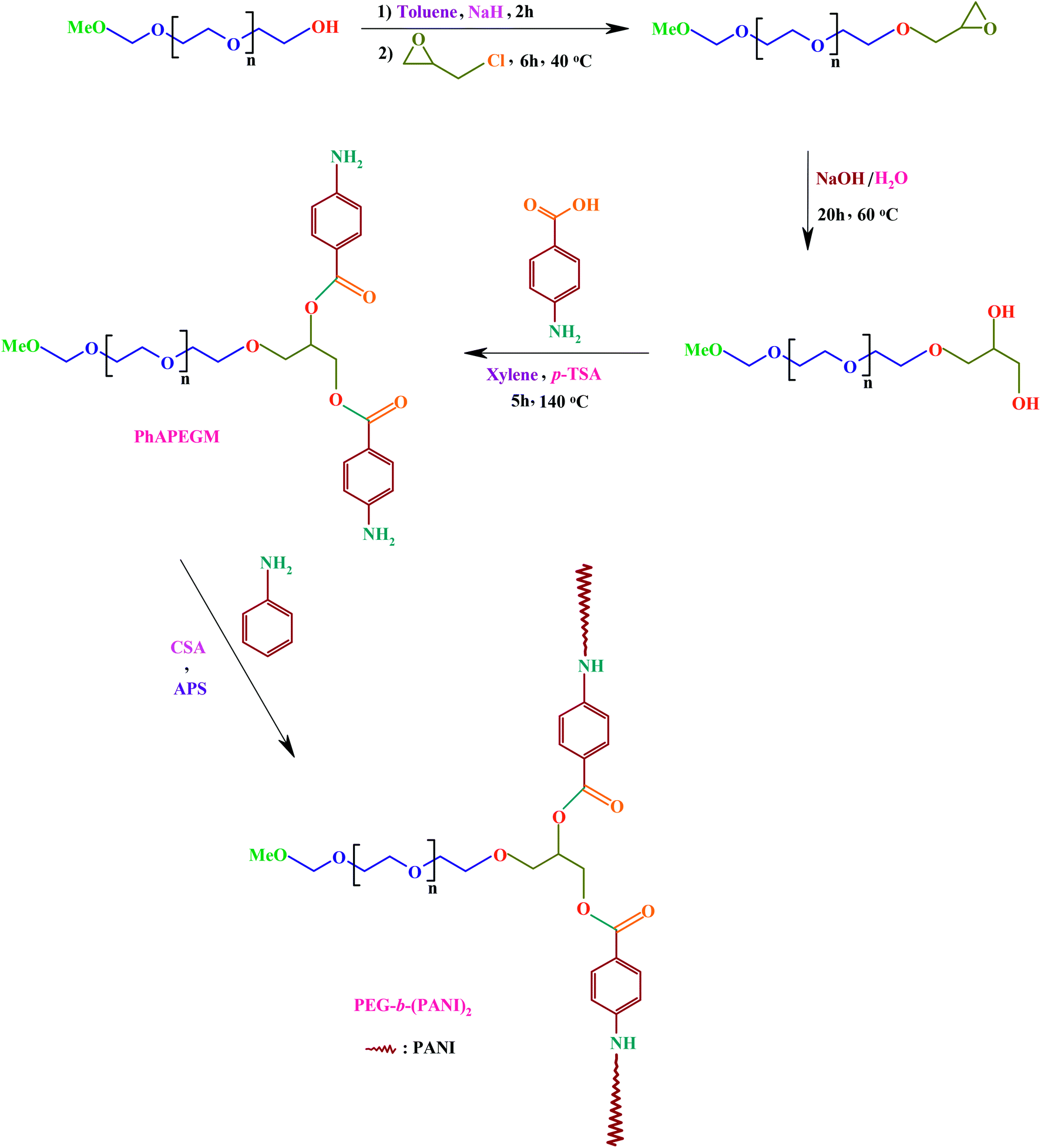 | ||
| Scheme 1 Synthetic route of the AB2 Y-shaped miktoarm star conductive polyaniline-modified poly(ethylene glycol). | ||
3.1. Synthesis of poly(ethylene glycol) end-caped epoxy
The FTIR spectra of the poly(ethylene glycol) monomethylether (a), and poly(ethylene glycol) end-caped epoxy (b) are shown in Fig. 1. The FTIR spectrum of the poly(ethylene glycol) monomethylether shows the characteristic absorption bands due to the stretching vibrations of aliphatic C–H (2950–2800 cm−1), hydroxyl stretching vibration (3480 cm−1), –CHx bending vibrations (1470 and 1372 cm−1), and C–O stretching vibration at 1126 cm−1. The FTIR spectrum of the poly(ethylene glycol) end-caped epoxy shows similar bands with minor differences. The most distinctive feature of the poly(ethylene glycol) end-caped epoxy in comparison with poly(ethylene glycol) monomethylether, in the FTIR spectra is decreasing intensity of hydroxyl stretching vibration at 3480 cm−1. It is verify that the most of the hydroxyl groups were converted to the epoxy groups.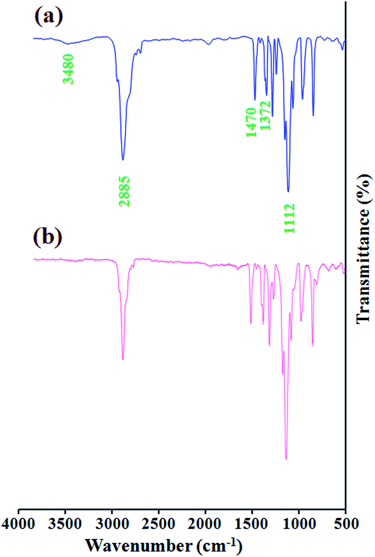 | ||
| Fig. 1 The FTIR spectra of the poly(ethylene glycol) monomethylether (a), and poly(ethylene glycol) end-caped epoxy (b). | ||
The 1H nuclear magnetic resonance (NMR) spectrum of the poly(ethylene glycol) end-caped epoxy is shown in Fig. 2. As shown in this Figure the peaks at 3.07–3.13 (c), 2.71–2.74 (d), and 2.53–2.55 (e) ppm are related to the epoxy end-caped group. In addition, the chemical shift at 2.44 ppm indicates that some of the hydroxyl group's does not converted to the epoxy group. According to 1H NMR spectrum results the degree of conversion calculated to be 77% by mol. These FTIR and 1H NMR spectra assignments verify that the poly(ethylene glycol) end-caped epoxy was successfully synthesized.
 | ||
| Fig. 2 The 1H nuclear magnetic resonance (NMR) spectrum of the poly(ethylene glycol) end-caped epoxy. | ||
3.2. Synthesis of phenylamine-functionalized poly(ethylene glycol) AB2 macromonomer (PhAPEGM)
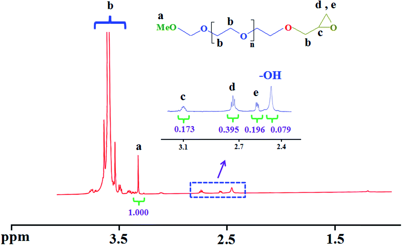
Macromonomers are usually referred to as reactive oligomers or polymers in which a polymerizable functional group(s) is incorporated into the chain end(s) or polymer backbone. Macromonomers can be synthesized using various methods such as anionic, cationic, and radical polymerization, as well as the chemical modification of polymer ends or backbone.40,41 The development of new polymeric materials usually requires the use of highly selective and efficient functionalization reactions. In this respect, nucleophilic substitution reaction has been proposed as one of the most powerful tool for functionalization of polymeric materials, in part due to its easy experimental setup, applicability to various functional groups, and tolerance to many solvents, and additives.The FTIR spectra of the poly(ethylene glycol) end-caped diol (a), and phenylamine-functionalized poly(ethylene glycol) AB2 macromonomer (PhAPEGM) (b) are shown in Fig. 3. The FTIR spectrum of the poly(ethylene glycol) end-caped diol shows the characteristic absorption bands due to the stretching vibrations of C–H (2950–2800 cm−1), hydroxyl stretching vibration (3446 cm−1), –CHx bending vibrations (1469 and 1374 cm−1), and C–O stretching vibration at 1108 cm−1.
 | ||
| Fig. 3 The FTIR spectra of the poly(ethylene glycol) end-caped diol (a), and phenylamine-functionalized poly(ethylene glycol) AB2 macromonomer (PhAPEGM) (b). | ||
The FTIR spectrum of the PhAPEGM macromonomer shows similar bands with minor differences. The most distinctive features of PhAPEGM in comparison with poly(ethylene glycol) end-caped diol, in the FTIR spectra are the appearance of new stretching vibration bands for C![[double bond, length as m-dash]](https://www.rsc.org/images/entities/char_e001.gif) C (1602 and 1482 cm−1), carbonyl (1692 cm−1), and amine groups (–NH2) (3394 and 3367 cm−1).
C (1602 and 1482 cm−1), carbonyl (1692 cm−1), and amine groups (–NH2) (3394 and 3367 cm−1).
Additional evidence for the synthesis of the phenylamine-functionalized poly(ethylene glycol) AB2 macromonomer (PhAPEGM) was also obtained from 1H nuclear magnetic resonance (NMR) spectroscopy. Fig. 4 shows the 1H NMR spectra of the poly(ethylene glycol) end-caped diol, and phenylamine-functionalized poly(ethylene glycol) AB2 macromonomer (PhAPEGM). In the 1H NMR spectrum of the poly(ethylene glycol) end-caped diol the chemical shift at 2.44 ppm is related to the hydroxyl end-caped groups. As can be seen in the 1H NMR spectrum of the PhAPEGM, after introducing of phenylamine groups to the poly(ethylene glycol) end-caped diol, two new peaks at 6.36–6.57 and 7.86–7.88 ppm corresponding to aromatic protons of phenylamine groups were appeared. In addition, the 1H NMR spectrum of the PhAPEGM indicates that all of the hydroxyl groups in the poly(ethylene glycol) end-caped diol, were converted to phenylamine groups, because the chemical shift of hydroxyl groups at 2.44 ppm is completely disappears.
 | ||
| Fig. 4 The 1H nuclear magnetic resonance (NMR) spectra of the poly(ethylene glycol) end-caped diol, and phenylamine-functionalized poly(ethylene glycol) AB2 macromonomer (PhAPEGM). | ||
3.3. Synthesis of AB2 Y-shaped miktoarm star conductive poly(ethylene glycol)-b-(polyaniline)2 copolymer
As a decisive fact, it should be pointed out that, copolymers in general exhibit physical and mechanical properties far different from those of blend of the same corresponding homopolymers. In the case of conductive polymers, an efficient and versatile approach for exploiting these polymers and overcoming their deficiencies is synthesis of their copolymers.2,3Two kinds of cation radicals initiate aniline polymerization after addition of oxidant. One is oxidized phenylamine groups coupled to the poly(ethylene glycol); the other is oxidized aniline cation radicals. With increasing reaction time, more aniline monomers join in the polymerization. Some are entrapped into the polymer chains initiated by oxidized phenylamine groups coupled to the poly(ethylene glycol) chains; others incorporate the polymer chains initiated by oxidized aniline cation radicals. These polyaniline chains could not be linked chemically to the poly(ethylene glycol). To remove the pure polyaniline, the crude product was purified as given in the Experimental section. The FTIR spectra of the PEG-b-(PANI)2 and pure PANI are shown in Fig. 5. The FTIR spectrum of the pure PANI (Fig. 5b) shows the characteristic absorption bands due to stretching vibration of the CN in the benzenoid units at 1502 cm−1, Caromatic–N stretching at 1315 cm−1, the stretching vibrations of aromatic C–H (3050–2900 cm−1), γ(C–H) in the aromatic ring (807 and 729 cm−1), and the N–H stretches at 3442 cm−1.
 | ||
| Fig. 5 The FTIR spectra of PEG-b-(PANI)2 (a), and pure PANI (b). | ||
The FTIR spectrum of the PEG-b-(PANI)2 (Fig. 5a) shows the characteristic absorption bands due to stretching vibration of the carbonyl (1720 cm−1), C–O stretching vibration at 1108 cm−1, –CHx bending vibrations (1486 and 1394 cm−1), aliphatic and aromatic stretching vibrations of C–H (3050–2800 cm−1), and the N–H stretches at 3442 cm−1.
Additional evidence for the synthesis of the miktoarm star conductive PEG-b-(PANI)2 was also obtained from 1H NMR data (Fig. 6). The 1H NMR spectrum of the PEG-b-(PANI)2 in D2O shows the chemical shifts at 7.27–7.39 ppm corresponding to the aromatic protons of polyaniline.
 | ||
| Fig. 6 The 1H nuclear magnetic resonance (NMR) spectrum of the PEG-b-(PANI)2 miktoarm star copolymer. | ||
The sharp peak at 4.70 ppm is related to the solvent (D2O). In addition, according to 1H NMR spectrum of PEG-b-(PANI)2 the number of attached aniline monomers onto functionalized PEG is calculated to be 40. Thus, the molecular weights of PANI segment(s), and the miktoarm star conductive PEG-b-(PANI)2 are 3720, and 5847, respectively. These FTIR and 1H NMR spectra assignments verify that the aniline has grown onto functionalized poly(ethylene glycol), and then the PEG-b-(PANI)2 was successfully synthesized.
3.4. Morphology and elemental composition
The field emission scanning electron microscopy (FE-SEM) image of PEG-b-(PANI)2 before electrospinning, and its energy dispersive X-ray (EDX) analysis are shown in Fig. 7. FE-SEM image shows the presence of two phase in the PEG-b-(PANI)2 copolymer. The light regions represent the poly(ethylene glycol) segments, and dark regions indicate polyaniline chains. As can be seen in FE-SEM image, the PEG has a globular morphology, which adhering to the surface. | ||
| Fig. 7 The FE-SEM image and EDX spectrum of the synthesized PEG-b-(PANI)2. | ||
Electrospinning is an efficient approach to fiber-forming process aided by the application of electrostatic forces to control the production of fibers. This technique is attractive due to the simplicity, cost-effectively, ability to effectively control the process, and potential for production scale-up.42 It is an unquestionable fact that electrospinning has stimulated great interest in the fabrication of scaffolds for repair and regeneration of human tissues, in part due to ultra-thin continuous fibers, high porosity, high surface-to-volume ratio, and adjustable pore size distribution.30,39,42
The FE-SEM images and EDX analysis's of the electrospun PCL (a–c), and PEG-b-(PANI)2/PCL (d–f) are shown in Fig. 8. The PCL electrospun nanofibers (Fig. 8a and b) shows high amounts of beads with diameters higher than 100 nm, which could be related to various parameters. These parameters have been extensively discussed elsewhere.43
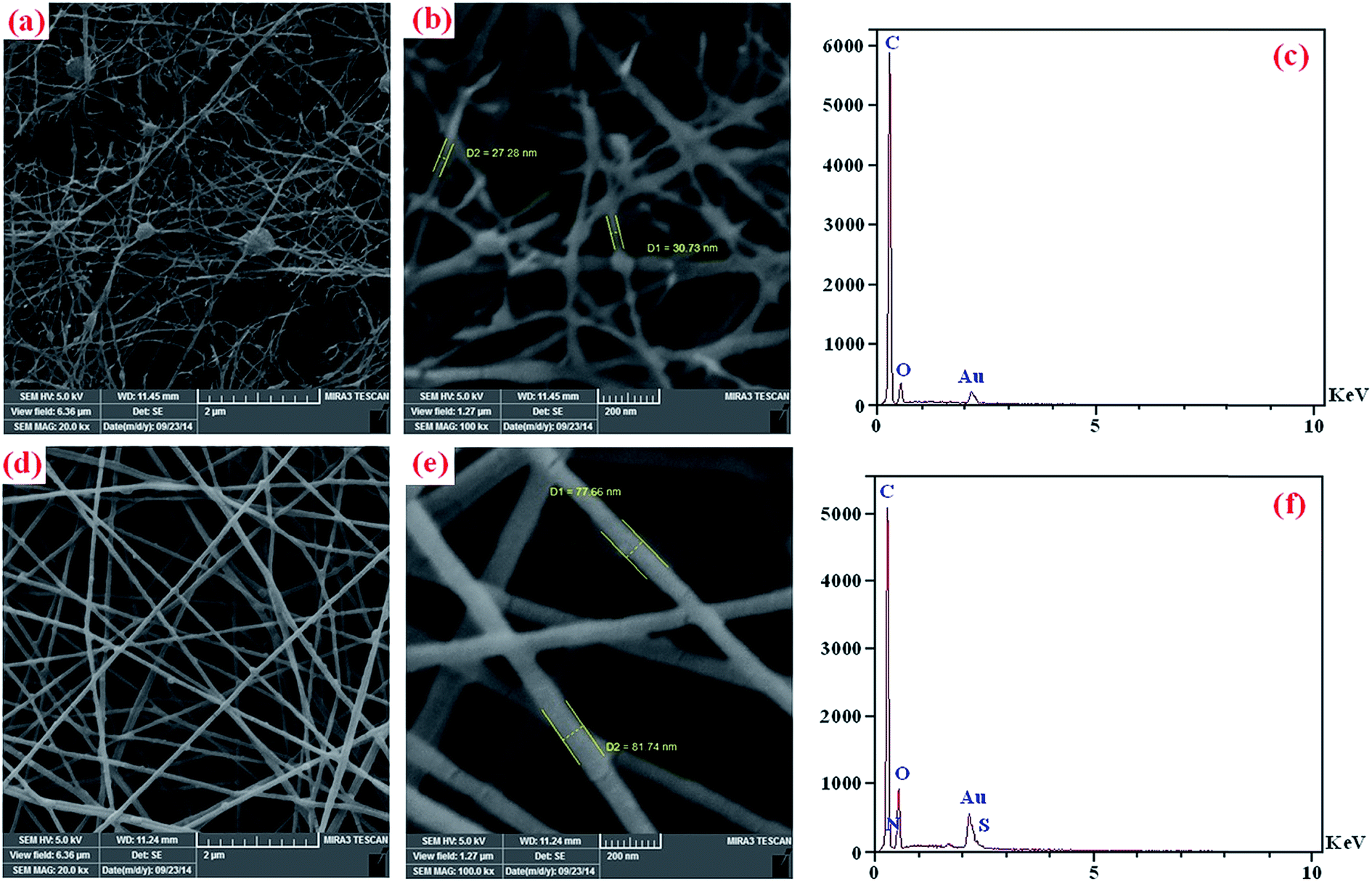 | ||
| Fig. 8 The FE-SEM images and EDX spectra of the electrospun PCL (a–c), and PEG-b-(PANI)2/PCL (d–f). | ||
As seen in Fig. 8d and e the formed beads in pure PCL could be influenced by the presence of synthesized PEG-b-(PANI)2. The electrospun nanofibers of PEG-b-(PANI)2/PCL presented a single phase indicating good interactions between the blend components. The average diameters of these fibers are in the size range of 70 ± 10 nm, and there were no formation of beaded structures in comparison with electrospun fibers of pure PCL. In addition, the results obtained from EDX analysis are summarized in Table 1.
| Sample | C (wt%) | O (wt%) | N (wt%) | S (wt%) |
|---|---|---|---|---|
| PEG-b-(PANI)2 | 42.07 | 27.77 | 14.80 | 15.36 |
| PCL | 83.03 | 16.97 | — | — |
| PEG-b-(PANI)2/PCL | 67.89 | 24.40 | 5.19 | 5.52 |
3.5. Solubility tests
The solubility of the PEG-b-(PANI)2 miktoarm star copolymer and pure PANI in common organic solvents are summarized in Table 2. Poly(ethylene glycol) has excellent solubility in polar organic solvents. As seen in this Table the solubility of PEG-b-(PANI)2 in common organic solvents improved compared to pure PANI, because aniline has grown onto poly(ethylene glycol).| Solvent | NMP | DMSO | DMF | THF | Acetonitrile | CHCl3 | 2-Chloroethanol | Xylene |
|---|---|---|---|---|---|---|---|---|
| a +++: soluble; ++: sparingly soluble; +: slightly soluble; -: insoluble; the concentration used in the solubility test was 10 mg of each polymer in 1 ml of solvents (NMP, N-methylpyrrolidone; DMSO, dimethylsulfoxide; DMF, dimethylformamide; THF, tetrahydrofuran). | ||||||||
| PANI | ++ | ++ | + | - | - | - | - | - |
| PEG-b-(PANI)2 | +++ | +++ | +++ | +++ | +++ | ++ | ++ | - |
3.6. Electrical conductivity and electroactivity measurements
Unlike to other type of polymers, π-conjugated polymers exhibit conducting and/or semiconducting behaviors and thus serve as potential candidates for technological and biomedical applications. It is well established that the use of π-conjugated polymers as tissue-engineering scaffold materials allows the conduction of natural electrical impulses, thus preventing effective cell–cell communication.16The electrical conductivities of all synthesized samples were measured at room temperature using the four-point probe technique. The experimental determination was repeated 5 times for each sample to evaluate the sample accuracy. Using the values of current (I), voltage (V), and thicknesses (d) of the samples, the volume specific resistivity (ρ; Ω cm), and subsequently, the electrical conductivity (σ; S cm−1) was calculated using the following formula.
| ρ = (V/I)(π/ln2)d |
| σ = 1/ρ |
The results obtained are summarized in Table 3. It is important to note that the conductivities were preserved for at least 100 hours post fabrication.
Among the electrochemical analysis methods, the cyclic voltammetry (CV) has become an important and widely used electroanalytical technique in many areas of chemistry. It is widely applied to investigate a variety of redox processes. The effect of the potential scanning rate (V) on the peak currents for the synthesized samples modified electrodes were studied in the range of 25–225 mV s−1 scan rate, in a aqueous solution of camphorsulfonic acid (0.5 mol l−1) (Fig. 9). The cyclic voltammograms (CVs) of the pure PANI (Fig. 9a) shows two typical redox couples with anodic peaks at approximately 0.18 and 0.56 V versus Ag/AgCl electrode. In contrast, for PEG-b-(PANI)2 the only one anodic peak at approximately 0.51 V versus Ag/AgCl electrode is observed (Fig. 9b). In addition, the anodic peaks current are linearly increased with increasing of scan rate. The cyclic voltammograms of the PEG-b-(PANI)2 indicated that the grafted PANI onto poly(ethylene glycol); still remained a good redox activity, and the resulting AB2 Y-shaped miktoarm star conductive polyaniline-modified poly(ethylene glycol) was highly stable.
 | ||
| Fig. 9 Cyclic voltammetry curves of pure PANI (a), PEG-b-(PANI)2 (b), electrochemically growth of PANI onto PEG-b-(PANI)2 at a scan rate of 100 mV s−1 (c), and [PEG-b-(PANI)2]-co-PANI (d). | ||
In additional experimental step, polyaniline was electrochemically polymerized onto PEG-b-(PANI)2 by applying sequential linear potential sweeps with a scan rate of 100 mV s−1 between −0.2 and +1.0 V versus silver (Ag)/silver chloride (AgCl) electrode (Fig. 9c). The PANI was deposited onto PEG-b-(PANI)2 through 10 cycles in the supporting electrolyte ([PEG-b-(PANI)2]-co-PANI). After electropolymerization of aniline onto PEG-b-(PANI)2 the effect of the potential scanning rate on the peak currents were studied. As shown in Fig. 9d, this sample shows two typical redox couples with anodic peaks at approximately 0.18 and 0.38 V versus Ag/AgCl electrode. Moreover, the anodic peaks shifts in the direction of positive potential with increasing scan rate, which indicates the electrochemical oxidation/reduction (doping/dedoping) was chemically reversible. To evaluate the electroactivity further the relationship between the peak current sizes versus scan rate was determined. Fig. 10 shows linear relationships between the current and scan rate between 25–225 mV s−1 for pure PANI, PEG-b-(PANI)2 and [PEG-b-(PANI)2]-co-PANI. This linear relationship is typical of redox-active polymers attached to the electrodes and also exemplifies the stability of the synthesized samples toward doping/dedoping.
 | ||
| Fig. 10 Linear relationship between current and scan rate in the PEG-b-(PANI)2, [PEG-b-(PANI)2]-co-PANI, and pure PANI (the currents in PANI and [PEG-b-(PANI)2]-co-PANI are related to the second anodic peaks). | ||
Fig. 11 shows the effect of the potential scanning rate (V) on the peak currents for the PEG-b-(PANI)2/PCL electrospun blend nanofibers modified electrode in the range of 25–225 mV s−1 scan rate, in a aqueous solution of camphorsulfonic acid (0.5 mol l−1). The cyclic voltammograms of this sample shows only one anodic peak at approximately 0.47 V versus Ag/AgCl electrode. As seen in this Figure the current density corresponding to the cathodic, and anodic peaks are gradually increased with increasing scan rate, which indicates the electrochemical oxidation/reduction (doping/de-doping) of the casted sample was chemically reversible. However, as seen in Fig. 11 similar to electrical conductivity (Table 3) the electroactivity of the PEG-b-(PANI)2/PCL was significantly decreased in comparison with electroactivity of the PEG-b-(PANI)2 miktoarm star copolymer, in part due to the presence of insulating poly(ε-caprolactone).
 | ||
| Fig. 11 Cyclic voltammetry curves of the PEG-b-(PANI)2/PCL. | ||
3.7. Thermal property study
The thermal behaviors of the obtained polymers upon heating under nitrogen atmosphere were investigated by means of thermogravimetric analysis (TGA). Characteristic TGA curves of the poly(ε-caprolactone), poly(ethylene glycol) monomethylether, PEG-b-(PANI)2/PCL, PEG-b-(PANI)2, and pure PANI are shown in Fig. 12. It is evident that the major decompositions of the poly(ε-caprolactone), poly(ethylene glycol) monomethylether, and polyaniline were occurring in one step around 250–390, 240–375, and 380–480 °C, respectively, and after which the loss rates slows down in these samples.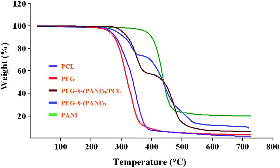 | ||
| Fig. 12 Thermogravimetric analysis of the pure poly(ε-caprolactone), poly(ethylene glycol) monomethylether, PEG-b-(PANI)2/PCL, PEG-b-(PANI)2, and pure PANI. | ||
However, the PEG-b-(PANI)2 miktoarm star copolymer undergoes a two-step decomposition; the first step corresponds to the decomposition of the poly(ethylene glycol) chain (260–380 °C), whereas the second step is associated with PANI chain scission (390–520 °C), after which the loss rate slows down. In similar, the PEG-b-(PANI)2/PCL undergoes a two-step decomposition; the first step corresponds to the decompositions of the poly(ethylene glycol), and poly(ε-caprolactone) chains (260–390 °C), whereas the second step is associated with PANI chain scission (400–520 °C), after which the loss rate slows down. According to the Fig. 12 we can draw the conclusion that the final weight residue at 750 °C, for the poly(ε-caprolactone), poly(ethylene glycol) monomethylether, PEG-b-(PANI)2/PCL, PEG-b-(PANI)2, and pure PANI were 2, 3, 8, 10, and 20 wt%, respectively.
4. Conclusion
This work has shown an efficient and novel approach for the synthesis of AB2 Y-shaped miktoarm star conductive polyaniline-modified poly(ethylene glycol) [PEG-b-(PANI)2]. The synthesis of PhAPEGM macromonomer, and PEG-b-(PANI)2 copolymer were confirmed by means of FTIR and 1H NMR spectroscopies. The growth of aniline onto functionalized poly(ethylene glycol) enhanced its solubility, and processability compared with pure polyaniline. The cyclic voltammograms (CVs) of the PEG-b-(PANI)2 exhibited some qualitative similarities with those of pure PANI. The CVs of PEG-b-(PANI)2 indicated that the grafted polyaniline onto PEG chains still remained a good redox activity in the resulting miktoarm star copolymer, and the synthesized copolymer was found to be highly stable. The conductivity and electroactivity measurements exhibited the PEG-b-(PANI)2 and PEG-b-(PANI)2/PCL electrospun blend nanofibers have lower electrical conductivity and electroactivity than those of the pure PANI. However, the lower electrical conductivity and electroactivity levels in these materials can be improved at the price of solubility, processability, and biocompatibility. Because of unique physicochemical properties, π-conjugated polymers have a wide range of applications from photovoltaic and electronic devices to nerve regeneration. Due to influences of electrical stimulation on the nerve regeneration, we predicted the conductive and biocompatible PEG-b-(PANI)2/PCL electrospun blend nanofibers can be used for the fabrication of conductive scaffolds to promote neurite outgrowth and nerve regeneration.Acknowledgements
We express our gratitude to the Payame Noor University, and Research Center for Pharmaceutical Nanotechnology, Tabriz University of Medical Sciences for supporting this project.References
- H. Shirakawa, E. J. Louis, A. G. MacDiarmid, C. K. Chiang and A. J. Heeger, Chem. Commun., 1977, 578–580 RSC
.
- M. Jaymand, Prog. Polym. Sci., 2013, 38, 1287–1306 CrossRef CAS PubMed
- M. Jaymand, M. Hatmazadeh and Y. Omidi, Prog. Polym. Sci., DOI:10.1016/j.progpolymsci.2014.11.004.
- M. Hatmazadeh, R. Mohammad-Rezaei and M. Jaymand, Mater. Sci. Semicond. Process., 2015, 31, 463–470 CrossRef PubMed
- F. Gu, X. Yin, H. Yu, P. Wang and L. Tong, Opt. Express, 2009, 17, 11230–11235 CrossRef CAS
- Y. Wang, H. D. Tran, L. Liao, X. Duan and R. B. Kaner, J. Am. Chem. Soc., 2010, 132, 10365–10373 CrossRef CAS PubMed
- F. Gu, L. Zhang, X. Yin and L. Tong, Nano Lett., 2008, 8, 2757–2761 CrossRef CAS PubMed
- M. Hatamzadeh and M. Jaymand, RSC Adv., 2014, 4, 28653–28663 RSC
- M. Hatamzadeh, A. Mahyar and M. Jaymand, J. Braz. Chem. Soc., 2012, 23, 1008–1017 CrossRef CAS PubMed
- H. Zhao, Z. Wang, P. Lu, M. Jiang, F. Shi, X. Song, Z. Zheng, X. Zhou, Y. Fu, G. Abdelbast, X. Xiao, Z. Liu, V. S. Battaglia, K. Zaghib and G. Liu, Nano Lett., 2014, 14, 6704–6710 CrossRef CAS PubMed
- J. Yang, R. Zhu, Z. Hong, Y. He, A. Kumar, Y. Li and Y. Yang, Adv. Mater., 2011, 23, 3465–3470 CrossRef CAS PubMed
- M. Jaymand, RSC Adv., 2014, 4, 33935–33954 RSC
- H. Gomez, M. K. Ram, F. Alvi, E. Stefanakos and A. Kumar, J. Phys. Chem. C, 2010, 114, 18797–18804 CAS
- M. R. Choi, T. H. Han, K. G. Lim, S. H. Woo, D. H. Huh and T. W. Lee, Angew. Chem., Int. Ed., 2011, 50, 6274–6277 CrossRef CAS PubMed
- S. Bhadra, N. K. Singha and D. Khastgir, Polym. Eng. Sci., 2008, 48, 995–1006 CAS
- T. H. Qazi, R. Rai, D. Dippold, J. E. Roether, D. W. Schubert, E. Rosellini, N. Barbani and A. R. Boccaccini, Acta Biomater., 2014, 10, 2434–2445 CrossRef CAS PubMed
- Y. Liao, V. Strong, W. Chian, X. Wang, X. G. Li and R. B. Kaner, Macromolecules, 2012, 45, 1570–1579 CrossRef CAS
- W. Serrano, A. Meléndez, I. Ramos and N. J. Pinto, Polymer, 2014, 55, 5727–5733 CrossRef CAS PubMed
- Y. K. Han, M. Y. Chang, K. S. Ho, T. H. Hsieh, J. L. Tsai and P. C. Huang, Sol. Energy Mater. Sol. Cells, 2014, 128, 198–203 CrossRef CAS PubMed
- B. Massoumi, Z. Mozaffari and R. Mohammadi, Int. J. Polym. Mater., 2014, 63, 800–807 CrossRef CAS
- H. Farrokhzad, M. R. Moghbeli, T. Van Gerven and B. Van der Bruggen, React. Funct. Polym., 2015, 86, 161–167 CrossRef CAS PubMed
- T. Homma, M. Kondo, T. Kuwahara and M. Shimomura, Eur. Polym. J., 2015, 62, 139–144 CrossRef CAS PubMed
- M. A. Corona-Rivera, V. M. Ovando-Medina and H. Martínez-Gutiérrez, Colloid Polym. Sci., 2015, 293, 605–615 CAS
- H. Wang, T. Ni, G. Li and Y. Li, Synth. Met., 2013, 177, 52–59 CrossRef CAS PubMed
- N. K. Guimard, N. Gomez and C. E. Schmidt, Prog. Polym. Sci., 2007, 32, 876–921 CrossRef CAS PubMed
- R. Ravichandran, S. Sundarrajan, J. R. Venugopal, S. Mukherjee and S. Ramakrishna, J. R. Soc., Interface, 2010, 79, 559–579 CrossRef PubMed
- Z. Yang, Z. Xue, Y. Liao, X. Zhou, J. Zhou, J. Zhu and X. Xie, Langmuir, 2013, 29, 3757–3764 CrossRef CAS PubMed
- P. Wang, K. L. Tan, F. Zhang, E. T. Kang and K. G. Neoh, Chem. Mater., 2001, 13, 581–587 CrossRef CAS
- F. F. Azhar, A. Olad and R. Salehi, Des. Monomers Polym., 2014, 17, 654–667 CrossRef
- M. Li, Y. Guo, Y. Wei, A. G. MacDiarmid and P. I. Lelkes, Biomaterials, 2006, 27, 2705–2715 CrossRef CAS PubMed
- J. C. C. Wu, S. Ray, M. U. B. Gizdavic-Nikolaidis, S. Swift, J. Jin and R. P. Cooney, Synth. Met., 2014, 198, 41–50 CrossRef CAS PubMed
- I. Rajzer, M. Rom, E. Menaszek and P. Pasier, Mater. Lett., 2015, 138, 60–63 CrossRef CAS PubMed
- E. I. Yslas, P. Cavallo, D. F. Acevedo, C. A. Barbero and V. A. Rivarola, Mater. Sci. Eng., C, 2015, 51, 51–56 CrossRef CAS PubMed
- H. Baniasadi, A. Ramazani and S. Mashayekhan, Int. J. Biol. Macromol., 2015, 74, 360–366 CrossRef CAS PubMed
- J. Zhang, K. Qiu, B. Sun, J. Fang, K. Zhang, H. EI-Hamshary, S. S. Al-Deyab and X. Mo, J. Mater. Chem. B, 2014, 2, 7945–7954 RSC
- L. Shadi, M. Karimi, A. A. Entezami and K. Dindar-Safa, Polym. Bull., 2013, 70, 3529–3545 CrossRef CAS PubMed
- R. Alizadeh, M. Karimi, R. Teimuri-Mofrad and A. A. Entezami, J. Polym. Res., 2014, 21, 521 CrossRef
- H. Ahmad, M. Rashid, M. M. Rahman, M. A. Jalil-Miah, K. Tauerb and M. A. Gafur, Polym. Int., 2014, 63, 667–673 CrossRef CAS PubMed
- R. Balint, N. J. Cassidy and S. H. Cartmell, Acta Biomater., 2014, 10, 2341–2353 CrossRef CAS PubMed
- M. Jaymand, Polym. Chem., 2014, 5, 2663–2690 RSC
- J. Tan, G. Zhao, Y. Lu, Z. Zeng and M. A. Winnik, Macromolecules, 2014, 47, 6856–6866 CrossRef CAS
- T. Jiang, E. J. Carbone, K. W. H. Lo and C. T. Laurencin, Prog. Polym. Sci., DOI:10.1016/j.progpolymsci.2014.12.001.
- J. M. Deitzel, J. Kleinmeyer, D. Harris and N. C. B. Tan, Polymer, 2001, 42, 261–272 CrossRef CAS
| This journal is © The Royal Society of Chemistry 2015 |