Photoreduction of natural redox proteins by CdTe quantum dots is size-tunable and conjugation-independent

Joanna Grzyb*a, Ewelina Kalwarczykb and Remigiusz Worcha
aInstitute of Physics PAS, al. Lotników 32/46, 02-668 Warsaw, Poland. E-mail: jgrzyb@ifpan.edu.pl
bInstitute of Physical Chemistry PAS, Kasprzaka 44/52, 01-224 Warsaw, Poland

Received 14th February 2015 , Accepted 13th July 2015

First published on 13th July 2015


Abstract

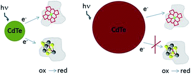
Colloidal CdTe quantum dots (QD) were able to reduce both heme and iron–sulfur cluster containing proteins. Reduction was depended on quantum dots size. CdTe nanocrystals emitting light with maximum at 550 nm (QD-550, r ∼ 1.5 nm) reduced both ferredoxin (Fd) and cytochrome c (Cyt c). The process was followed by UV/Vis absorption spectroscopy and steady state fluorescence spectroscopy. For CdTe emitting longer wavelength (QD-610 and QD-670) reduction of Fd was less efficient. QD emitting light with maximum at 750 nm (QD-750, r ∼ 3.3 nm) reduced only Cyt c. Reduction of proteins by QDs was photo-dependent and did not demand oxygen presence. As shown by gel filtration and fluorescence correlation spectroscopy, Fd formed complexes with QD while Cyt c did not bound steadily. The stable complex was not necessary for photoreduction, although might influence its kinetics. Time-resolved fluorescence studies showed than electron transfer rate depends on QD size and also is higher for QD–Cyt c when compared to QD–Fd. The mechanism of process was additionally explored by detailed analysis of QD–protein complex formation and by measurements of cyclic voltamperometry and zeta potential. These results open new possibilities in controlling of natural redox processes.


Introduction

Quantum dots (QDs), being nanometer-scale crystals of semiconductor materials, are widely used as luminescent probes in several fields of life science.1 Redox reactions, occurring close to the nanocrystal surface, may modify QDs fluorescence, which is used in sensors development.2–6 It is known that QDs incorporated into biomimicking systems may conduct electrons.7 There is a strong evidence of fluorescence energy transfer between QDs and coupled luminophores, but there is no direct proof of photoinduced electron transfer from QD to biomolecules, such as proteins with redox centers. Such a transfer is crucial for QDs applications in biological studies, both in vivo and in vitro (for recent review see ref. 8). The only available recent report showed that myoglobin, bound to CdTe surface by covalent attachment of heme, was photoreduced.9 There are no studies comparing photoreduction mediated by QDs of different diameter, while it is known that nanocrystal size may be important factor influencing conjugates behaviour. For example, in our work about ferredoxin–NADP+ oxidoreductase covalently attached to CdSe/ZnS nanoparticles we observed different behaviour of enzyme in dependence of QD size, suggesting that electron properties of surface may depend of surface/volume ratio.10

Here we demonstrate that CdTe quantum dots can be used as electron donor for biological electron carriers, bovine heart cytochrome c (Cyt c) and spinach ferredoxin (Fd), without the necessity of covalent conjugation. As reduction of biological molecule depends on its midpoint potential (Em), it is possible to tune reduction level by choosing QDs of different size. This opens a new possibility in powering and controlling of biological reactions.

Experimentals

Quantum dots and proteins

CdTe quantum dots, with 3-mercaptopropionic acid shell (QD) and maximum emission of 550 nm (QD-550), 610 nm (QD-610), 670 nm (QD-670) and 750 nm (QD-750) were obtained from PlasmaChem Gmbh (Germany). Stock solutions were prepared by dissolving 1–3 mg of dry powder in MQ water, and stored at 4 °C in darkness. Molar concentrations were calculated based on experimental extinction coefficients.11 For 10 mg ml−1 stock solutions it was respectively 318 μM QD-550, 116 μM QD-610, 78 μM QD-670 and 46 μM QD-750. The values did not differ significantly from values obtained by using molar coefficient provided by QDs manufacturer (Plasmachem Gmbh, Germany).

Ferredoxin was isolated from commercially available spinach leaves by procedure described in ref. 12 with modification. Soluble protein fraction obtained after hydration of acetone powder was dialyzed against 50 mM Tris/HCl pH 8.0 and loaded on HiTrap Q column (GE Healthcare). Proteins were eluted by linear gradient of NaCl and fractions of 1 ml were collected. If necessary, ferredoxin was additionally purified by gel filtration on Superdex 75 10/300 (GE Healthcare). Fractions containing pure ferredoxin were collected, dialysed against 25 mM phosphate buffer pH 8.0 and stored frozen until further use. Concentration of ferredoxin was calculated according to ε420 = 9.8 mM−1 cm−1.12

Cytochrome c from bovine heart was obtained from Sigma-Aldrich Co. Concentration of oxidized protein was calculated according to ε410 = 140 mM−1 cm−1.

Illumination experiments

Protein–QD mixture was prepared from deoxygenated buffer (bubbled with nitrogen for at least 30 min), concentrated proteins (30–50 μM) and QDs stocks (5–10 μM). All preparations and mixing were done in dim white light (<10 μE). Final concentrations for most experiments were 0.1 μM QD and 4 μM Fd or 1 μM Cyt c. Fd concentration was optimized for convenient reduction determination from spectral changes. Basically, absorption of 4 μM Fd at 415 nm is about 0.04. After complete reduction, it is reduced by about 50% (0.02 absorption unit). Lower Fd concentration might result in changes more influenced by noise, especially if the reduction was just partial. QD concentration was chosen after preliminary experiments, showing measurable change in absorption in reasonable time scale. Lower Cyt c concentration was chosen because of strong QD fluorescence quenching by this protein, affecting FCS and gel filtration analysis. Cyt c has much higher extinction coefficient and determination of spectral changes was not subjected by apparatus sensitivity. The QD–protein mixture was additionally bubbled with nitrogen for 2–3 min and transferred to quartz cuvettes (fluorescence type) with gas-tight screw caps, and then closed under nitrogen. For comparison of illumination and darkness incubation, as prepared mixture was split in aliquots into two identical cuvettes. One of the samples was placed in darkness, while second one was subjected spectroscophotometric and spectrofluorymetric measurements and then illuminated by placement on quartz glass about 2 cm above UV bulb (305 nm, 8 W) for given time (5–30 min), at temperature 22 °C.

UV-Vis spectroscopy and steady-state fluorescence measurement

UV-Vis spectra were measured using Cary 50Bio spectrophotometer. Steady-state fluorescence was measured with Cary Eclipse, with measuring parameters optimised for our system (excitation and emission slits – 5 nm, sensitivity – medium).

Time resolved fluorescence studies

Fluorescence lifetime measurements were performed using the Zeiss LSM710 microscope with LSM upgrade kit (PicoQuant, Berlin, Germany). Concentrations of QDs were adjusted to 0.25 μM and concentration of Fd and cyt c were levelled respectively. All solutions were deoxygenated prior to experiment and kept in darkness. The signal was collected by excitation with a wavelength of 485 nm with a pulsed diode laser (pulse frequency: 8 MHz for QD750 and 40 Hz in other cases), focused by C-Apochromat 40×, 1.2 NA water immersion objective in the droplet of QD solutions placed on a glass cover slip (24 × 65 mm, #1.5, Carl Roth). Emission was recorded using a 510 longpass filter. Single photons (∼104 at peak) were registered with an avalanche photo diode using time-correlated single photon counting (TCSPC). The decay curves were analyzed in the range not affected by the instrument response function (“tail-fit”). A non-linear least squares iterative fitting procedure was applied to obtain the fluorescence lifetimes of QDs by fitting a sum of three exponential decays. The average lifetime was calculated as τav = (ΣAiτi2Aiτi).13 Electron transfer rate (kET) was calculated as 1/τ(QD+protein) − 1/τQD, in accordance to ref. 14 and 15.

FCS measurement

FCS measurements were performed on Zeiss 780 ConfoCor 3 microscope with a C-Apochromat 40×, numerical aperture (NA) 1.2 water immersion objective at room temperature (24.0 ± 0.3 °C). Experimental details as described in ref. 10 with the detection range optimized to cover emission range of QDs.

Gel filtration

Gel filtration was done using Superdex 75 10/300 column (GE Healthcare), connected to Akta Purifier. Elution was monitored by internal spectrophotometric detector of chromatography system. Measurement was done at three wavelengths simultaneously – 280 nm, 415 nm and third wavelength chosen accordingly to QD type – 510 nm, 585 nm, or 645 nm, or 706 nm. HMW Calibration Kit (GE Healthcare) was used for determination of Stoke's radius.

Zeta potential determination of QD and QD protein mixtures

The values of zeta potential and of hydrodynamic diameter of QD and QD–protein mixtures were determined with Zetasizer NanoZS (Malvern Instruments Ltd.). The applied light source was He–Ne laser: 633 nm, max 4 mW. The data was analysed with Zetasizer Software, version 7.03. The measurements were performed at 22 °C.

Electrochemistry

Cyclic voltamperometry was measured with potentiostat PGSTAT101 (Metrohm Autolab B.V., Netherlands). Home-made mini-electrode setup consisted of platinum grid as working electrode, platinum wire as counter electrode and Ag/AgCl reference electrode. Platinum electrodes were cleaned before each measurement by short fire treatment and additional cyclisation in 0.5 M H2SO4. During measurements the solutions were gently stirred by magnetic stirrer. Anaerobic conditions were assured by applying nitrogen stream above solution surface.

Results

The proteins used in presented experiments were chosen due to the redox changes manifested in their UV-Vis spectrum, and because they have different Em: +225 mV in case of Cyt c16 and −415 mV for Fd.17 Fd and Cyt c are similar in molecule size and radius (Fd – 14 kDa, r ∼ 1.6 nm, Cyt c – 12.5 kDa, r ∼ 1.6 nm), but they are different in carried redox cofactor (iron sulfur cluster and heme, respectively), as well as in overall protein charge and distribution of charged amino acids. Isoelectric point (pI) of Fd is about 4.5 what makes it negatively charged in our buffer conditions (pH 8.0), while pI of Cyt c is 9.5 and its overall charge is positive. Four types of CdTe quantum dots – with emission maximum at 550 nm (QD-550), at 610 nm (QD-610), at 670 nm (QD-670) and at 750 nm (QD-750) were used in order to obtain significant difference in surface electron energy.18

Spectrophotometric characterization of ferredoxin and cytochrome c reduction process

To investigate if photo-generated electrons can be transferred from QD to redox active proteins we tested two proteins, with different redox potential – spinach Fd and Cyt c from bovine heart. It is known, that Cyt c may be reduced by superoxide,19 which can be created by electron transfer from QDs to oxygen. To eliminate such scenario, we used strict anaerobic conditions in all following experiments.

Absorption spectrum of spinach Fd in UV-Vis range contains band characteristic for tryptophan (maximum 278 nm) and broad bands which are characteristic features for iron–sulfur cluster. There is a maximum at 400–420 nm, arm at about 350 nm and additional maximum at about 520–550 nm. Illumination of Fd in the presence of QD with different sizes may result in different changes in its absorption spectrum (Fig. 1). Illumination of Fd with QD-550 is by significant decrease of absorption intensity in whole range 350–400 nm (Fig. 1a). These spectral changes are known to relate to reduction of Fd.20 Incubation of Fd with QD-550 nm without illumination did not cause such changes. As shown in Fig. 1c, 30 min incubation was necessary to completely reduce Fd present in sample. Complete reduction (100% of possible change in the spectrum) was defined as change in Fd–QD spectrum at 420 nm, after addition of saturating concentration dithionite. This chemical is known to completely reduce Fd as well as Cyt c. The presence of QD-610 led to complete reduction of Fd, with kinetics similar to that of QD-550. QD of higher diameter, namely QD-670, allowed only for 50% maximal reduction after 30 min. In case of QD-750, no changes in UV-Vis spectrum were found, (both illuminated and incubated in darkness, Fig. 1b).


image file: c5ra02900g-f1.tif
Fig. 1 Comparison of the UV-Vis spectra of mixture of CdTe quantum dots (0.1 μM) (a) – QD-550, (b) – QD-750 (inset – zoom in on the 400–600 nm region of spectrum and of spinach ferredoxin (4 μM), before treatment and after 30 min of incubation in darkness and after illumination (UV ∼ 305 nm, 8 W)), (c) – changes in the reduction level during illumination of Fd in presence of all tested QDs. Incubation was carried out in anaerobic conditions, at 22 °C.

Incubation of QD with Fd resulted in about 25% decrease in the fluorescence intensity of illuminated all types of QD and did not influenced significantly intensity of its fluorescence after incubation at darkness.

Cyt c, diluted in water or in phosphate buffer, has an absorption spectrum that is characteristic for oxidized heme proteins. It consists of tryptophan absorption peak (maximum at 278 nm) and a narrow absorption maximum at 410 nm with broader band around 500 nm. As shown in Fig. 2a, when the mixture of Cyt c and QD-550 was illuminated for 5 min, it induced significant changes in UV-Vis spectrum. The main band of the Cyt c spectrum shifts from 410 to 414 nm. The second band (around 500 nm) changes from one broad band to two sharper bands with maxima at 520 nm and 550 nm. The same changes were obtained for Cyt c treated with dithionite (data not shown) and are typical for reduced form of this protein.21 For parallel samples, incubated in darkness, there were only weak changes, although of the same type, suggesting that even non-illuminated QDs had some surface electrons that can be transferred to the heme moieties. Reduction of Cyt c was stable – no significant changes of spectrum were observed for at least 1 h of following incubation of illuminated samples when stored in darkness or weak light. However, for samples illuminated for longer time, bleaching and changes in UV-Vis spectrum resulted in disappearance of QDs as well as back-oxidation of Cyt c. Addition of Cyt c itself quenched intensity of QDs fluorescence. Such fact was already used for quantification of heme and hemin.22 For that reason the concentration of Cyt c was adjusted to the level allowing detection of QDs emission. The 30 min incubation with Cyt c additionally decreased fluorescence intensity of QD-750 band – for about 20% during illumination and for 10% for parallel sample, incubated in darkness (not shown). In case of QD-550 the change was more significant – the intensity decreased by about 15% in darkness and by 45% during illumination.


image file: c5ra02900g-f2.tif
Fig. 2 Changes in the UV-Vis spectrum of mixture of CdTe quantum dots (0.1 μM) and cytochrome c (1 μM), after 5 min of incubation in darkness or at illumination (UV ∼ 305 nm, 8 W). (a) – QD-550, (b) – QD-750, (c) – changes in the reduction level during illumination in presence of all tested QD types. Incubation was carried out in anaerobic conditions, at thermostated room temperature.

For analogous experiment with QD-750 we also observed changes in UV-Vis spectrum corresponding to reduction, although occurring with different kinetics – after 5 min of incubation reduction level was similar to that observed with QD-550 (Fig. 2b), while after 30 min of incubation, it drastically decreased to about 10% of maximum, (Fig. 2c). For other tested QD types (QD-610 and QD-670) we also observed Cyt c reduction. The process led to about 60% of maximal possible reduction after 5 min illumination, and then following re-oxidation. The reoxidation was slowest for QD-670.

The prolonged incubation with Cyt c additionally decreased fluorescence intensity of QD-750 – for about 20% during 30 min illumination and for 10% for parallel sample that was incubated in darkness. For smaller QDs the decrease of the fluorescence intensity was more significant, and reached 15% in darkness and by 45% for illuminated QD-550 (data not shown).

Size analysis – gel filtration

Radius of Fd calculated from its crystal structure is 1.6 nm what is in very good agreement with 1.7 nm that we obtained from gel filtration. Regarding the radius of Cyt c, as calculated from its crystal structure, it equals to about 1.6 nm what is bigger than calculated from gel filtration (1.4 nm). It suggests that Cyt c in solution may adapt slightly more compact conformation than in crystal structure.

When the protein–QDs mixtures were analyzed by gel filtration, we found an increase in the nanocrystals size (all QD types) when Fd was present (Fig. 3). In the presence of Cyt c no changes was observed for QD-750 and QD-550 (Fig. 4). Small shift in elution volume was detected for QD-610 and significant shift for QD-670.


image file: c5ra02900g-f3.tif
Fig. 3 Elution profile of Fd incubated for 30 min with QD-550 (a) or with QD-610 (b), QD-670 (c) or QD-750 (d). Incubation details at Fig. 1. Separation carried out at Superdex 75 10/300 (GE Healthcare), in 25 mM phosphate buffer, pH 8.0. Detection at 280 nm. QDs concentration was 0.1 μM and Fd concentration was 4 μM for all variants. Differences in absorption values are due to different extinction coefficients of nanocrystals.

image file: c5ra02900g-f4.tif
Fig. 4 Elution profile of cytochrome incubated 30 min with QD-550 (a) or with QD-610 (b), QD-670 (c) or QD-750 (d). Incubation details at Fig. 2. Separation carried out at Superdex 75 10/300 (GE Healthcare), in 25 mM phosphate buffer, pH 8.0 buffer. Detection at 415 nm due to better extinction of Cyt c. QDs concentration was 0.1 μM and Cyt c concentration was 1 μM all variants. Differences in absorption values are due to different extinction coefficients of nanocrystals.

Stokes radii, calculated from elution profile was about 3.1 nm for pure QD-750 and increased to about 3.3 or 3.7 nm after incubation with Fd, in darkness or under illumination, respectively. In case of QD-550, pure nanocrystals eluted at volume corresponding to radius 1.3 nm. After incubation with Fd, elution volume decreased and corresponded to a radius of 3.2 nm. The elution profile was weekly dependent on illumination. Stokes radii calculated for all variants of experiments are provided in Fig. 3 and 4. Analysis of fractions collected during elution confirmed that increase in QD size was related to complex formation between QD and Fd – fluorescence emission spectrum contains both QDs band and tryptophan band (ESI, Fig. S-1). It should be mentioned that in case of QD-550 and Cyt c mixtures there was no fluorescence signal of QDs in any of fractions. This fact may be the result of strong quenching of QD fluorescence by Cyt c or unspecific interaction of QDs with column beads. Noteworthy, to observe elution of free QD-550 we needed to increase concentration by 5 times in comparison to QD-750. Peaks corresponding to free proteins (elution volume at 14 ml and at 15 ml, for Fd or Cyt c, respectively) were also found in elution profile. These peaks were the proteins excess, present in incubation mixture and were not influenced by incubation – its elution volumes were exactly the same as for free protein, not incubated with QDs.

Size analysis – fluorescence correlation spectroscopy (FCS)

Gel filtration may produce artefacts due to interaction with beads (mentioned earlier problems with elution of free QD-550), especially when huge complexes are formed. Therefore we additionally confirmed the complex formation by fluorescence correlation spectroscopy (FCS). We found (see Table 1, ESI Fig. S-2) that the radii of QDs increased by 0.5–1.5 nm. The increase was more significant for illuminated samples, except QD-550. After incubation with Cyt c in darkness, radii of QDs did not changed significantly, while during illumination we observed an increase in radii up to 8 nm for QD-550 and QD-610. The increase of QD radius changed with illumination time, as it is shown for QD-550 at Fig. 5. The contradiction between FCS and gel filtration results, especially for QD-550, may be explained by stacking of QD–Cyt c complex to the column, or decomposition of weakly interacting complexes after interaction with beads. Then, no free QD-550 were detected just because of its fluorescence quenching by heme.22 It is also possible, that due to the high variation in radius, the complexes eluted as a very broad peak (or even smear) with low, hardly detectable amplitude. We could exclude the last hypothesis, since we did not detect spectrophotometrically any traces of Cyt c in any other fraction than those corresponding to free Cyt c.
Table 1 Radii calculated from FCS measurements for all experiment variants, compared with theoretical radii11 for nanocrystal part of QDs. Samples were prepared as described in Fig. 1 and 2. R – theoretical radius
QD type R [nm] Pure QD [nm] QD + Fd, darkness [nm] QD + Fd, UV [nm] QD + Cyt c, darkness [nm] QD + Cyt c, uv [nm]
QD-550 1.32 1.7 ± 0.8 2.3 ± 0.1 1.9 ± 0.1 1.6 ± 0.1 7.9 ± 2.5
QD-610 1.72 2.3 ± 0.8 3.4 ± 0.5 4.1 ± 1.5 1.5 ± 0.1 8.0 ± 2.5
QD-670 2.12 2.7 ± 0.5 3.7 ± 0.8 4.2 ± 0.6 2.7 ± 0.3 3.8 ± 0.8
QD-750 3.15 3.3 ± 0.7 3.6 ± 0.1 4.2 ± 0.1 3.7 ± 0.3 3.7 ± 0.4


image file: c5ra02900g-f5.tif
Fig. 5 Changes of effective radius and brightness of QD-550 and Cyt c mixtures with the increase of the illumination time (details as in Fig. 2). Brightness is represented by counts per particle (cpp), that is average brightness divided by the number of particles in the confocal volume.

Electron transfer rate determined by time-resolved fluorescence

The electron transfer rate between QDs and non-fluorescent electron acceptor (here Fd or Cyt c), may be estimated from changes in fluorescence decay of QDs.15 ESI (Fig. S-34) shows examples of normalized luminescence decay curves recorded for all QD variants in absence or in presence of proteins. Table 2 summarizes average decay times (τ) calculated from at least three repetitions, as well as kET estimated from those values. Average luminescence lifetime increases with QD diameter, from 15.9 ns for QD-550 to about 115.0 ns for QD-750. Decays were fitted with three-exponential decays, however with increased QD size, the longest τ became predominant (from fraction 0.42 for QD-550 to 0.81 for QD-750). In presence of Fd or Cyt c, the best fit also demanded three exponentials. In presence of Fd, τ was reduced significantly for QD-550 and QD-610, while for QD-670 and QD-750 were almost unchanged. Presence of Cyt c resulted in drastic reduction of τ for QD-550, QD-610 and QD-670. For QD-750 the change is also significant. kET from QDs to Fd was almost the same for QD-550 and QD-610, what correspond to kinetics shown in Fig. 1c. Electron transfer from QD-670 and QD-750 to Fd is much slower, what again corresponds to lower reduction efficiency. Rate of electron transfer from QD to Cyt c is greater than to Fd, but also decreases with increasing QD size.
Table 2 Average lifetimes of QDs in solution, in presence or absence of Fd or Cyt c. Electron transfer rate (kET) calculated as in ref. 15
QD type τ QD [ns] τ (QD + Fd) [ns] τ (QD + Cyt c) [ns] kET Fd [μs−1] kET Cyt c [μs−1]
QD-550 15.9 ± 0.5 13.9 ± 0.1 6.8 ± 0.6 9.0 ± 2.0 75 ± 13
QD-610 34.2 ± 4.0 25.7 ± 2.6 11.2 ± 1.3 9.7 ± 5.2 50 ± 11
QD-670 44.4 ± 4.6 44.1 ± 3.0 19.0 ± 2.7 0.2 ± 2.8 29.9 ± 7.6
QD-750 115.0 ± 14.1 107.7 ± 14.9 54.5 ± 3.5 0.6 ± 1.7 9.1 ± 1.7


Zeta potential and hydrodynamic diameter of quantum dots in presence of proteins

The ability to transfer electron from particle surface may depend on its total charge and charge distribution. Both these properties may be estimated by zeta potential, measured from electrophoretic mobility of colloids. Zeta potential of particles is also an indirect indicator of aggregation tendencies and informs about changes in surface cover.

Then, interaction of QD with protein may result in change of overall particle charge. Due to huge standard errors of QD zeta potential measurements, the results cannot be interpreted as absolute values and should be rather treated as general trends. In our experiment, zeta potential for pure QDs (Fig. 6) was negative and decreased with the increase of QD radius. Such a trend was previously shown in literature.23,24 The presence of Cyt c increases zeta potential of all CdTe nanoparticles to about −20 mV. The ζ-potential of QD incubated with Fd was in the range of −30 to 40 mV. The presence of Fd resulted in decrease of zeta potential of smaller CdTe quantum dots and increase in zeta potential of biggest tested nanoparticle type (QD-750).


image file: c5ra02900g-f6.tif
Fig. 6 Changes of zeta potential of pure QDs, pure or incubated with Cyt c or Fd in the darkness. Error bars correspond standard error determined from three independent repetitions. The concentration of QDs (0.5 μM) was higher than for all other measurements because of techniques recruitments. To keep protein[thin space (1/6-em)]:[thin space (1/6-em)]QD ratio unchanged, Fd concentration was increased to 20 μM and Cyt c to 5 μM. Incubation with proteins were done in darkness for 30 min in 22 °C.

We also determined hydrodynamic diameter of pure QDs and QD–protein mixtures using dynamic light scattering with Zetasizer NanoZs. Due to limitation of the apparatus, we were only able to determine size of QD-610 and its mixtures with Fd and Cyt c. Diameter of free QDs was calculated as 4.3 ± 2.7 nm. For QDs incubated with Cyt c we observed diameter 5.0 ± 1.5 nm which confirms lack of stable complexes between QDs and this protein. Diameter of QD-610 with Fd was 18.2 ± 2.0 nm and this is significantly bigger than that of free QDs. This observation confirms stable Fd–QD complex formation.

Redox potential of quantum dots

While zeta potential informs about average charge of molecule, the ability of molecule to donate or accept electrons is described by its redox potential. Redox potential may be determined by cyclic voltamperometry which we employed here. The convenient parameter for comparison is the midpoint potential (Em) which is defined as the voltage at which equilibrium between the concentrations of oxidized and reduced form of the substance occurs. The lower the Em, the more potent the reductant is. To explain the observed results we also determined redox potential of QDs and their mixtures with Fd or Cyt c. As it is shown in Fig. 7, CdTe quantum dots reduction and oxidation results in clearly detectable transition, dependent on nanocrystal size. The smaller the crystal, the lower both Em and position of anodic current peak. The value of cathodic current also increased with the QDs size but less significantly than anodic current. The Em was −1.0 V for QD-550, −0.92 V for QD-610, −0.90 V for QD-670 and −0.72 V for QD-750. With the increase of the nanoparticle size the amplitude of current also decreased, from 1.96 mA for QD-550 to 0.29 mA for QD-750. The presence of Fd and Cyt c did not changed significantly anodic and cathodic current values of QD-550 it darkness. After illumination anodic current peak was shifted to −1.11 in the presence of Cyt c and to −1.09 V in presence of Fd. Cathodic current was −0.83 V for both proteins. Similar behaviour was observed for QD-610. For QD-670 and QD-750 in presence of proteins, both anodic and cathodic current were shifted for about 10–20 mV to higher values, both in the darkness and after illumination. Presence of CdTe also modified position of cathodic and anodic peak coming from working electrode alone. Additional anodic and cathodic arm were detected for QD-550 and QD-750, at values lower than main signal. In all case there were also additional cathodic peak at about 0 V that was not present in buffer.
image file: c5ra02900g-f7.tif
Fig. 7 Cyclic voltammograms of QDs solutions. Cyclic voltammogram recorded for pure buffer is shown as reference. Concentration of QD was 1 μM in all cases.

Discussion

It became recently evident, that nanoparticles of different types are able also to significantly influence enzymatic reactions.25,26 For example, CdSe/ZnS quantum dots were shown to increase catalytic performance of E. coli alkaline phosphatase25 as well as reduce Michaelis constant (Km) of plant ferredoxin–NADP + oxidoreductase.10 Phosphotriesterase activity was also enhanced by nanocrystals.27 Studies of electron–hole behaviour of several QDs suggest that QDs may become also a light-triggered electron donor. The electron/hole potential depends on QD size in similar manner as energy of emitted photons.18 QDs were proved to be able to transfer electrons to metal oxides.28 The electron transfer from QD to oxygen may cause generation of reactive oxygen species (superoxide or singlet oxygen) and damage of the cell,29 but may also be the base for cancer phototherapy.30,31 Here we demonstrated that QDs composed of CdTe may reduce natural redox proteins, ferredoxin and cytochrome c. The reduction demands illumination of QDs and in the process the electrons are transferred directly for QD surface to protein redox centre. Although oxygen may participate in such process,29 we proved that it is not necessary since reduction occurs in strictly anaerobic conditions.

As shown in Fig. 8, both Fd and Cyt c have their cofactors at least partially water exposed. It makes possible electron transfer with water-dispersed QDs without forming stable specific contacts between reaction partners. The observed reduction may be explained by process similar to photocurrent generation, namely dislocation of electrons due to photon absorption and its transfer from nanoparticle surface to another molecule, which is ready to accept the electron. Photocurrent generation was shown for example in system containing CdSe nanoparticles immobilized on gold electrodes.32 In our case, light induced electrons are not transferred to electrode surface but to iron–sulfur cluster or heme, what manifest itself in changing of spectral properties of those protein cofactors.


image file: c5ra02900g-f8.tif
Fig. 8 Ribbon representation of crystal structures (upper panel) with surfaces corresponding to charged residues (lower panel, blue corresponds to basic residues and red to acid ones) of (a) spinach ferredoxin (pdb: 1a70) and (b) bovine cytochrome c (pdb: 2b4z), with its cofactors – 2Fe2S of ferredoxin (represented as gray and yellow balls) and heme of cytochrome c (represented as orange-colored sticks).

All used quantum dots were able to photoreduce Cyt c, while Fd was not reduced by QD-750. Reduction efficiency of Fd simply decrease with increasing QD size, suggesting that it is related to band gap value. Efficiency of Cyt c reduction is similar for all tested QD types, reaching 60% after 5 min of illumination. The equilibrium state is reached after longer illumination (15 or 30 min) at lower level, especially for QD-710 at 5% of maximum possible reduction. Low level (up to 15%) of Cyt c reduction was found also at zero time, suggesting that the surface of QD, even at non-illuminated state, contain some free electrons, which can be transferred at acceptor. These electrons may be attributed to relatively high Em since no such behaviour is found for Fd and may be the result of surface defects during solubilization. The competitive reactions, leading to decrease of Cyt c reduction level, may be the self-aggregation of QDs, related to change in free QD size especially after illumination (Fig. 5). Since the lightness of illuminated QDs decreased the mechanism of this process probably involves the formation of nonradiative recombination centers.33 Such nanocrystals may suffer from neutralization of the surface charge and finally aggregation in clusters of few particles, since we observed also significantly lower electrophoretic mobility of those samples (not shown). In case of Fd containing experiment variants, self-aggregation is minimized by proteins, covering QD surface.

The fluorescence decays were dependent of QDs type. As already shown in literature,34 fluorescence lifetime increased significantly with CdTe nanocrystals diameter. The average lifetimes we measured were higher 2–3 times from values shown previously in literature. The fluorescence decay for QD may strongly depend on environment.34 The effect we observed was most probably due to lack of oxygen in our system which is known fluorescence quencher.13 In aerobic solution the values indeed decreased (not shown). In presence of proteins average lifetime decreased, more significantly for QD–Cyt c mixture. Assuming that all changes in decay are due to electron transfer, we calculated electron transfer rates (kET). The pattern of it changes is corresponding to Fd and Cyt c reduction kinetics – the values are higher for smaller nanocrystals, and electron transfer form QD to Cyt c occurs at least 5 times faster. It is should be also noted that transfer rates are comparable to those measured between semiconductors – for PbS–TiO2 system it was 0.45–1.19 μs.

Literature data for CdTe quantum dots capped with oleic acid35 as well as thioglycolic acid36 shows that position of reduction and oxidation peaks is size dependent. In our experiments both position of anodic and cathodic peaks as well as Em were also size-dependent, although obtained values were not strictly fitting to previously published data. Those differences may be attributed to the differences in surface cover of nanocrystals as well as detailed characteristics of electrode system. It should be noted that both literature and measured Em of all QDs are lower than Em of Fd and Cyt c and we should observe reduction in all cases. Our result shows that properties of photogenerated electrons did not directly mirror Em value. QD-750 are not able to reduce Fd, but there is still size-dependency between photo Em and QD size. More detailed explanation comes from analysis of molecular orbitals values (Fig. 9). Energy of QDs LUMO is higher from LUMO of Fd in all cases except QD-750. Electron transfer to Fd is then possible from conductive band of QD-550, QD-610 and QD-670, and forbidden for QD-750. ΔE is higher for smaller QDs, what may be one of the factors causing faster kinetic of electron transfer. The LUMO energy of Cyt c is lower from QDs LUMO in all considered cases, then electron transfer is indeed possible for all QD tested. ΔE are significantly higher than in case of Fd, what again may influence final electron transfer rate.


image file: c5ra02900g-f9.tif
Fig. 9 Schematic diagram of HOMO and LUMO energies of CdTe QDs series in comparison to appropriate energies for Fd and Cyt c redox-active site. HOMO/LUMO for QDs estimated based on method described in ref. 15, values for Fd taken from ref. 40 and values for Cyt c estimated based on ref. 41 and 42.

The kinetics of reduction may be also impacted by QD–protein complex formation. The QD geometry (a sphere, here with radius from 1.3 to 3.2) allows maximal simultaneous attachment of about 4 (to QD-550) to 14 (QD-750) Fd/Cyt c molecules. Reduction of more molecules needs detachment of reduced ones. Since we observed stable complex formation between Fd and QD, then reduction of next Fd molecules needs detachment and substitution of the first molecule by another. For Cyt c which does not form stable complexes there is no need for that exchange and reduction may occur faster.

As pointed out in the paper, the formation of QDs conjugates with Cyt c or Fd were not simple explainable by electrostatic interactions. Ferredoxin, although being negatively charged, created stable complex with all tested QDs, possessing negatively charged surface. Such behaviour may be explained by presence of positively charged patch on ferredoxin molecular surface (Fig. 8a). Similar binding of protein to nanoparticles on “wrong side of pI” was described already for Au–TTMa nanoparticle interacting with serum albumin and beta-lactoglobulin.37 The Cyt c behaviour did not fit to this explanation, since its surface is rich in positively charged amino acids (Fig. 8b). This is most probably caused by screening of Cyt c surface by phosphate anions, because low electrophoretic mobility of mammalian Cyt c was observed in phosphate buffer in comparison to other buffer system tested.38 Theoretical calculations39 also showed that surface charge and interfacial dielectric constant may be strongly influenced by solvent ions.

In conclusion, we showed that CdTe quantum dots may become direct, electron donors to redox-active proteins, containing heme or iron–sulfur clusters. Electron transfer is photogenerated, depends on difference in energy of conductive band of QDs and lowest unoccupied molecular orbital of redox-active center of protein. Electron transfer does not need carrier molecule involvement. Reduction level may be tuned by choosing different size of QDs. Reduction does not demand strong and stable bonding, but may occur just at transient complex between protein and QD.

Author contributions

JG designed and conducted experiments except FCS and fluorescence decay measurements. RW performed FCS and fluorescence decay measurements and analyzed data. EK participated in zeta-sizer measurement and analysis. JG and RW wrote manuscript.

Acknowledgements

The research was financially supported by National Centre for Research and Development (Lider/012/445/L-4/12/NCBR/2013). Most of measurements were done in laboratories of NanoFun, POIG.02.02.00-00-025/09. We thank Dr Anna Niedzwiecka for the access to the spectrofluorometer founded by the Polish National Science Centre grant no. N N301 26713.

Notes and references

  1. I. L. Medintz, H. T. Uyeda, E. R. Goldman and H. Mattoussi, Nat. Mater., 2005, 4, 435–446 CrossRef CAS PubMed.
  2. R. Gill, L. Bahshi, R. Freeman and I. Willner, Angew. Chem., 2008, 120, 1700–1703 CrossRef PubMed.
  3. P. Wu, Y. He, H.-F. Wang and X.-P. Yan, Anal. Chem., 2010, 82, 1427–1433 CrossRef CAS PubMed.
  4. C. Huang, S. Liu, T. Chen and Y. Li, Sens. Actuators, B, 2008, 130, 338–342 CrossRef CAS PubMed.
  5. C. Guo, J. Wang, J. Cheng and Z. Dai, Biosens. Bioelectron., 2012, 36, 69–74 CrossRef CAS PubMed.
  6. J. C. Breger, K. E. Sapsford, J. Ganek, K. Susumu, M. H. Stewart and I. L. Medintz, ACS Appl. Mater. Interfaces, 2014, 6, 11529–11535 CAS.
  7. F. Wang, X. Liu and I. Willner, Adv. Mater., 2013, 25, 349–377 CrossRef CAS PubMed.
  8. D. A. Hines and P. V. Kamat, ACS Appl. Mater. Interfaces, 2014, 6, 3041–3057 CAS.
  9. A. Onoda, T. Himiyama, K. Ohkubo, S. Fukuzumi and T. Hayashi, Chem. Commun., 2012, 48, 8054–8056 RSC.
  10. K. Szczepaniak, R. Worch and J. Grzyb, J. Phys.: Condens. Matter, 2013, 25, 194102 CrossRef PubMed.
  11. W. W. Yu, L. H. Qu, W. Z. Guo and X. G. Peng, Chem. Mater., 2003, 15, 2854–2860 CrossRef CAS.
  12. M. Bojko and S. Wieckowski, Phytochemistry, 1999, 50, 203–208 CrossRef CAS.
  13. J. R. Lakowicz, Principles of fluorescence spectroscopy, Springer Science & Business Media, 2007 Search PubMed.
  14. P. V. Kamat, J. P. Chauvet and R. W. Fessenden, J. Phys. Chem., 1986, 90, 1389–1394 CrossRef CAS.
  15. B.-R. Hyun, Y.-W. Zhong, A. C. Bartnik, L. Sun, H. D. Abruna, F. W. Wise, J. D. Goodreau, J. R. Matthews, T. M. Leslie and N. F. Borrelli, ACS Nano, 2008, 2, 2206–2212 CrossRef CAS PubMed.
  16. P. L. Dutton, D. F. Wilson and C. P. Lee, Biochemistry, 1970, 9, 5077–5082 CrossRef CAS.
  17. R. Cammack, K. K. Rao, C. P. Bargeron, K. G. Hutson, P. W. Andrew and L. J. Rogers, Biochem. J., 1977, 168, 205–209 CAS.
  18. T. Rajh, O. I. Micic and A. J. Nozik, J. Phys. Chem., 1993, 97, 11999–12003 CrossRef CAS.
  19. J. M. McCord and I. Fridovich, J. Biol. Chem., 1970, 245, 1374–1377 CAS.
  20. S. G. Mayhew, D. Petering, G. Palmer and G. P. Foust, J. Biol. Chem., 1969, 244, 2830–2834 CAS.
  21. J. Macyk and R. van Eldik, Dalton Trans., 2003, 13, 2704–2709 RSC.
  22. J. Han, Z. Zhou, X. Bu, S. Zhu, H. Zhang, H. Sun and B. Yang, Analyst, 2013, 138, 3402–3408 RSC.
  23. T. Pons, H. T. Uyeda, I. L. Medintz and H. Mattoussi, J. Phys. Chem. B, 2006, 110, 20308–20316 CrossRef CAS PubMed.
  24. Y. Zhang, Y. Chen, P. Westerhoff and J. C. Crittenden, Environ. Sci. Technol., 2008, 42, 321–325 CrossRef CAS.
  25. J. C. Claussen, A. Malanoski, J. C. Breger, E. Oh, S. A. Walper, K. Susumu, R. Goswami, J. R. Deschamps and I. L. Medintz, J. Phys. Chem. C, 2015, 2208–2221 CAS.
  26. B. J. Johnson, W. Russ Algar, A. P. Malanoski, M. G. Ancona and I. L. Medintz, Nano Today, 2014, 9, 102–131 CrossRef CAS PubMed.
  27. J. C. Breger, S. A. Walper, E. Oh, K. Susumu, M. H. Stewart, J. R. Deschamps and I. L. Medintz, Chem. Commun., 2015, 51, 6403–6406 RSC.
  28. D. F. Watson, J. Phys. Chem. Lett., 2010, 1, 2299–2309 CrossRef CAS.
  29. J. Lovric, S. J. Cho, F. M. Winnik and D. Maysinger, Chem. Biol., 2005, 12, 1227–1234 CrossRef CAS PubMed.
  30. A. M. Pekkanen, M. R. DeWitt and M. N. Rylander, J. Biomed. Nanotechnol., 2014, 10, 1677–1712 CrossRef CAS PubMed.
  31. Y. Ghasemi, P. Peymani and S. Afifi, Acta Bio Med. Atenei Parmensis, 2009, 80, 156–165 Search PubMed.
  32. W. Khalid, G. Gobel, D. Huhn, J. M. Montenegro, P. Rivera-Gil, F. Lisdat and W. J. Parak, J. Nanobiotechnol., 2011, 9, 46 CrossRef CAS PubMed.
  33. W. G. van Sark, P. L. Frederix, D. J. van den Heuvel, H. C. Gerritsen, A. A. Bol, J. N. van Lingen, C. de Mello Donega and A. Meijerink, J. Phys. Chem. B, 2001, 105, 8281–8284 CrossRef CAS.
  34. A. Mandal, J. Nakayama, N. Tamai, V. Biju and M. Isikawa, J. Phys. Chem. B, 2007, 111, 12765–12771 CrossRef CAS PubMed.
  35. S. K. Haram, A. Kshirsagar, Y. D. Gujarathi, P. P. Ingole, O. A. Nene, G. B. Markad and S. P. Nanavati, J. Phys. Chem. C, 2011, 115, 6243–6249 CAS.
  36. S. K. Poznyak, N. P. Osipovich, A. Shavel, D. V. Talapin, M. Gao, A. Eychmuller and N. Gaponik, J. Phys. Chem. B, 2005, 109, 1094–1100 CrossRef CAS PubMed.
  37. K. Chen, Y. Xu, S. Rana, O. R. Miranda, P. L. Dubin, V. M. Rotello, L. Sun and X. Guo, Biomacromolecules, 2011, 12, 2552–2561 CrossRef CAS PubMed.
  38. G. H. Barlow and E. Margoliash, J. Biol. Chem., 1966, 241, 1473–1477 CAS.
  39. T. Simonson and D. Perahia, Proc. Natl. Acad. Sci. U. S. A., 1995, 92, 1082–1086 CrossRef CAS.
  40. L. Türker, Sci. World J., 2012, 2012 Search PubMed.
  41. H. Chen, Y. Wang, S. Dong and E. Wang, Electroanalysis, 2005, 17, 1801–1805 CrossRef CAS PubMed.
  42. V. Sharma, M. Wikström and V. R. Kaila, Biochim. Biophys. Acta, Bioenerg., 2010, 1797, 1512–1520 CrossRef CAS PubMed.

Footnote

Electronic supplementary information (ESI) available: Fluorescence analysis of fraction from gel filtration, example of FCS curves, example of fluorescence decay curves. See DOI: 10.1039/c5ra02900g

This journal is © The Royal Society of Chemistry 2015
Click here to see how this site uses Cookies. View our privacy policy here.