
Effects of the surface modification of carbon fiber by growing different types of carbon nanomaterials on the mechanical and thermal properties of polypropylene
F. Ghaemia,
R. Yunus*ab,
M. A. M. Sallehab,
S. A. Rashidab,
A. Ahmadianc and
H. N. Limad
aInstitute of Advanced Technology (ITMA), Universiti Putra Malaysia, 43400 UPM, Serdang, Selangor, Malaysia. E-mail: robiah@upm.edu.my; Tel: +60122306009
bDepartment of Chemical and Environmental Engineering, Faculty of Engineering, Universiti Putra Malaysia, 43400 UPM, Serdang, Selangor, Malaysia
cDepartment of Mathematics, Faculty of Sciences, Universiti Putra Malaysia, 43400 UPM, Serdang, Selangor, Malaysia
dDepartment of Chemistry, Faculty of Sciences, Universiti Putra Malaysia, 43400 UPM, Serdang, Selangor, Malaysia
First published on 17th March 2015
Abstract
The potential usage of different types of carbon nanoparticles in the herringbone, tubular and sheet structures of graphene plates, such as carbon nanofibers (CNF), carbon nanotubes (CNT) and graphene (G) flakes and also CNF–G and CNT–G on the carbon fiber (CF) surface as fillers in composite materials, is discussed in this paper. The combination of 2D graphene of high charge density and 1D CNTs or CNFs of large surface areas generates a versatile 3D hybrid network with synergic properties. A one-step process, chemical vapour deposition technique has been applied to synthesis these carbon nanoparticles (1D, 2D and 3D structures) by use of bimetallic catalyst (Ni/Cu). The morphology and chemical structure of the fibers, which have an effect on the polymer properties, were characterized by means of scanning electron microscopy, transmission electron microscopy, and specially Raman spectroscopy. These techniques were used to identify carbon nanoparticles, access their dispersion in polymers, evaluate filler/matrix interactions and detect polymer phase transitions. Compared with the neat CFs, the synthesized hybrid fibers led to an increase of the BET surface area from 0.7 m2 g−1 to 46 m2 g−1. Besides that, polypropylene (PP) composites with different carbon-based fillers, such as G on CF (CF–G), CNF on CF (CF–CNF), CNT on CF (CF–CNT) and also CF–CNF–G and CF–CNT–G were prepared by the melt mixed method, and the effects of these particles on the mechanical and thermal properties were analyzed. The mechanical results were confirmed by a mathematical model that state the mechanical reinforcement of the resultant composites strongly depends on the type of filler used. Noteworthy, composites based on combination of G and CNT presented the highest mechanical and thermal properties than those based on other carbon nanoparticles.
Introduction
Advanced polymer-based nanocomposites have been produced with improved properties, such as electrical conductivity, mechanical, and thermal stability.1,2Carbon fiber (CF) has been widely used to reinforce a composite because of its high strength and low weight.3 A small amount of this filler in the polymer matrix has revealed remarkable improvement of the thermal and mechanical properties.4–6 Carbon nanofibers (CNF) and carbon nanotubes (CNT) as rod-shaped fillers, with their high aspect ratios, enhance the polymer properties in the polymer composite, significantly.7–9 Initially, the CNTs in a polymer matrix were reported by Ajayan et al. in 1994.10 Since then, polymer composites of carbon nanoparticles have been studied in various research fields, mostly focusing on their mechanical applications.11–17 A strong interaction between these carbon nanomaterials and the host polymer is the key for mechanical strength. The bulk mechanical strength and stiffness of such composite is directly dependent on the interface of the polymer matrix with carbon nanoparticles. The elongated cylindrical forms of both CNTs and CNFs result in anomalously a large interface area per particle.18–21
The graphene plates are at an angel to the fiber axis in the herringbone shape to form a carbon nanofiber, and tubular graphene walls are parallel to the fiber axis in the carbon nanotube.22 Graphene (G) with a two-dimensional structure and honeycomb lattice is the most stable carbon format standard condition, which was discovered by Novoselov et al.23
The growing of graphene flakes with a 2D structure on CNT or CNF with a 1D structure makes a 3D structure. A few experimental approaches have been developed to fabricate the 3D nanostructures from a hybrid of graphene and CNT or CNF.24 For instance, Du et al. demonstrated a 3D structure consisting of several layers of graphene with CNTs grown on them perpendicularly.25 Also, Zhu et al. developed a method to bond graphene and a single-walled carbon nanotube carpet.26,27
This nanomaterial has the potential to be applied in both scientific research and industrial applications because of its remarkable characteristics in terms of the mechanical, thermal and electrical properties.28,29 Additionally, G was investigated as an outstanding reinforcing filler to compose a composite with good dispersion.30,31
The properties of composite materials depend not only on the reinforcing fillers and polymer matrix but also on the interfacial adhesion between them. High interfacial adhesion provides the strong structure of composites with an effective load transfer from the polymer matrix to the fiber. The growth of carbon nanoparticles on CF has been reported to increase the surface area of CF in order to improve the interfacial adhesion between the fiber and the matrix.32–34 Hence, the carbon nanomaterials, such as G and CNF, on CF fabricate a robust network with a polymer matrix to enhance the interfacial properties of the composites.35
Although there are several methods to obtain carbon nanomaterials, such as arc-discharge,36 laser ablation,37 chemical vapor deposition (CVD),38–41 self assembly,42 chemical reduction of graphite oxide,43 and liquid exfoliation,44 those based on chemical solution are stressed by their practical approach to scale up the production.
Chemical vapor deposition (CVD), as the most effective method, has been applied to grow carbon nanoparticles.45–47 To achieve different structures and morphologies, some critical parameters of CVD, such as growth time, growth temperature, flow rate of carbon source gas and catalyst concentration can be varied.48–51
The catalyst solution has a critical role to synthesize the CNF, CNT and also the G layers. Several studies have been carried out by using Ni and/or Cu as catalysts to grow CNF, CNT and G. To synthesize high quality graphene, CVD on Cu is considered as one of the most promising methods because of its fabrication in a large-area and a single-layer graphene.52–56 In addition, Ni is one of the most widely studied catalysts for the synthesis of carbon nanofibers,57,58 CNT59 and also graphene60,61 because a strong Ni–C interaction causes a repulsive interaction within the C–C interaction and causes the dissolution at the edge of the graphene.62 However, limited research has been devoted to the usage of a bimetallic catalyst (Ni/Cu) to synthesize CNF, CNT and G. The CuNi alloy is an excellent binary system to control carbon solubility by tuning the atomic fraction of Ni in Cu.63–65
To the best of our knowledge, so far, nobody has reported any work being widely carried out on synthesizing and comparing different kinds of carbon nanoparticles grown on CF in order to increase the surface area of the CF as well as to improve its properties. The Brunauer, Emmet, and Teller analysis (BET) was applied for measurements of specific surface area. The surface morphology and structural characterization of the samples were analyzed through scanning electron microscopy (SEM), transmission electron microscope (TEM) and Raman spectroscopy. Also, in this study, we have applied different analyses, such as Raman spectroscopy, tensile test and thermal gravimetric analysis, to investigate the influences of the structure, shape and morphology of the carbon nanoparticles on the mechanical and thermal properties of polypropylene composites.
Polypropylene (PP) is one of the most widely used polymers in automobiles, housewares, packaging, and electronics because of several useful properties.66–68 As such, PP has been used in many applications and mixed with various nanofillers in order to improve its mechanical properties.69 In this research, the produced fillers were incorporated into a polypropylene (PP) matrix to fabricate the nanocomposite. Furthermore, the effects of these fillers were investigated in terms of the mechanical and thermal properties of the PP composite. To this end, the tensile test and the thermal gravimetric analysis (TGA) were applied.
Besides those, in this study, Raman spectroscopy has a main role to characterize the graphitic carbon nanomaterials, being widely applied over the last four decades to characterize carbon fiber,70 nanographitic ribbons,71 fullerene,72 carbon nanotubes73,74 and graphene.75 Moreover, the sp2 nanocarbonous materials, such as graphene, carbon nanofibers and carbon nanotubes are characterized related to crystallite size, clustering of the sp2 phase, the presence of sp2–sp3 hybridization and the introduction of chemical impurities, defects and other crystal disorders, edge structure, number of graphene layers and the diameter of the nanotubes and nanofibers.76 So in this research, we have considered some of the mentioned aspects of the Raman spectra, which have enough sensitivity to evaluate the similarities and differences between the carbon nanoparticles as well as provide the micromechanical behaviors of the carbon nanoparticles in the polymer matrix.
Experimental
Materials
In this study, an unsized CF (Toho Tenax Co. Ltd.) was utilized as a substrate and activated by immersing it in nitric acid (65%). Additionally, a high purity acetylene (C2H2) as a carbon source, and nitrogen (air product, 99.9995) and hydrogen as carrier gases were used. Copper nitrate trihydrate (Cu(NO3)2·3H2O) and nickel nitrate hexahydrate (Ni(NO3)2·6H2O) as catalyst sources were utilized in the experimental part. Polypropylene pellets (PP 600G) were purchased from Petron at the Polymer Marketing and Trading Division, Malaysia and utilized as the polymer matrix.Synthesis of carbon nanoparticles on the CF
The treated carbon fibers were immersed into a mixture of copper nitrate trihydrate and nickel nitrate hexahydrate solution (70%, 30%) and followed by ultrasonic agitation for 2 h. After that, they were dried and calcinated under airflow at 200 °C for 2 h in order to remove the nitrate components and make the desired catalyst coating on the surface of the CF. The chemical vapor deposition method was applied for the synthesis of the CNF, CNT and G on the CF at atmospheric pressure and the temperatures at 600 °C, 800 °C and 1050 °C. This process was carried out by a catalytic reaction of an acetylene flow rate (50 standard cubic centimeters per minute (sccm)) over Ni–Cu/CF under a flow rate of H2/N2 (100, 100 sccm) in the reactor. Finally, the C2H2 flow was stopped, the heater was turned off and then the reactor was cooled under the flow of N2. In order to grow G flakes on the CNF or CNT, the temperature was increased to 1050 °C under H2/N2 (100, 100 sccm) and then the acetylene (50 sccm) was inserted into the reactor to obtain the G layers. The schematic representation of the carbon nanoparticles has been indicated in Fig. 1. | ||
| Fig. 1 Scheme diagram of the carbon nanoparticles growth on the CF surface. | ||
The characterization and determination of the crystallization, structure and surface area of the resulting CF–CNF, CF–CNT, CF–G, CF–CNF–G and CF–CNT–G were fulfilled by X-ray diffraction, Raman spectroscopy and the BET surface area, respectively. The crystallite parameters (d002 and R) of the samples were evaluated from the XRD and Raman spectra,31 where R was the ratio of the integrated intensity of the D peak to the G peak from the Raman spectra and the d002 was the position of the (002) peak (2θ) in the XRD patterns. Besides that, the morphology of the product was inspected through a scanning electron microscope (SEM) and transmission electron microscope (TEM).
BET surface analysis
According to the ISO 9277, the Brunauer–Emmett–Teller (BET) method was utilized to calculate the specific surface areas of the CF and CNP/CF hybrid fibers using an adsorption instrument (BELSORP-mini II analyzer).Composite preparation
To prepare the composite, firstly, the polypropylene (PP) was melted and blended by a mixer (Thermo Haake Poly Drive R600/610) at 180 °C with a 55 rpm rotor speed for 5 min. and then mixed with fillers (5 wt%) and blended for 15 min.77 After that, the blended composite was put in a mold of the size 15 × 15 cm with a 1 mm thickness, allowed to melt at 180 °C under a pressure of 150 kg cm−2 by way of a HSINCHU Hot Press Machine and then cooled to 60 °C.Characterization of the composites
The specimen with a thickness of 1 mm was cut into dumbbell shapes according to the ASTM D638 standard.78 An Instron Universal Testing Machine was used to do a tensile test at room temperature to measure the modulus of elasticity and the strength of PP, CF/PP, CF–CNF/PP, CF–CNT/PP, CF–G/PP, CF–CNF–G/PP and CF–CNT–G/PP. The tests were carried out with a crosshead speed of 5 mm min−1.79 Moreover, to determine the thermal stability and degradation resistance of the nanoparticle composites a thermal gravimetric analysis (TGA) test was applied.80 TGA was fulfilled on a Mettle Stare SW 9.10 thermal gravimetric analyzer. First of all, the sample (0.65 mg) was put in the specimen holder and heated to 200 °C for a few minutes to remove the water. Then, the heating program started from 25 °C to 900 °C with a 10 °C min−1 heating rate under a nitrogen flow.Results and discussion
Structural and surface characterization
Fig. 2(a) shows the typical SEM images of the pristine carbon fiber with 5–6 μm and 500 μm in diameter and length, respectively. After the adsorption and decomposition of the carbon source by the CVD process, all the carbon fibers were uniformly covered with a high density of carbon nanoparticles. As illustrated in Fig. 2(b), the graphene flakes were grown on the carbon fiber surface. Since the graphene flakes have a sheet structure, therefore, some of them lay and some of them stand up on the surface of carbon fiber coated by the catalyst particles. The synthesized CNFs with a 1D structure form a 3D network structure on the carbon fiber surface (see Fig. 2(c)). Fig. 2(d) depicts a SEM image of the grown graphene on the fabricated CNF–CF surface. As it is depicted the graphene flakes on CNF surface make a 3D structure. The micrograph in Fig. 2(e) illustrates the synthesized CNTs on the CF surface and finally, in Fig. 2(f), the graphene grown on the resulting CF–CNT has been shown. In the CNF–CF and CNT–CF cases, the graphene falkes not only were grown on the CNF and CNT surfaces but also synthesized on the carbon fiber surface.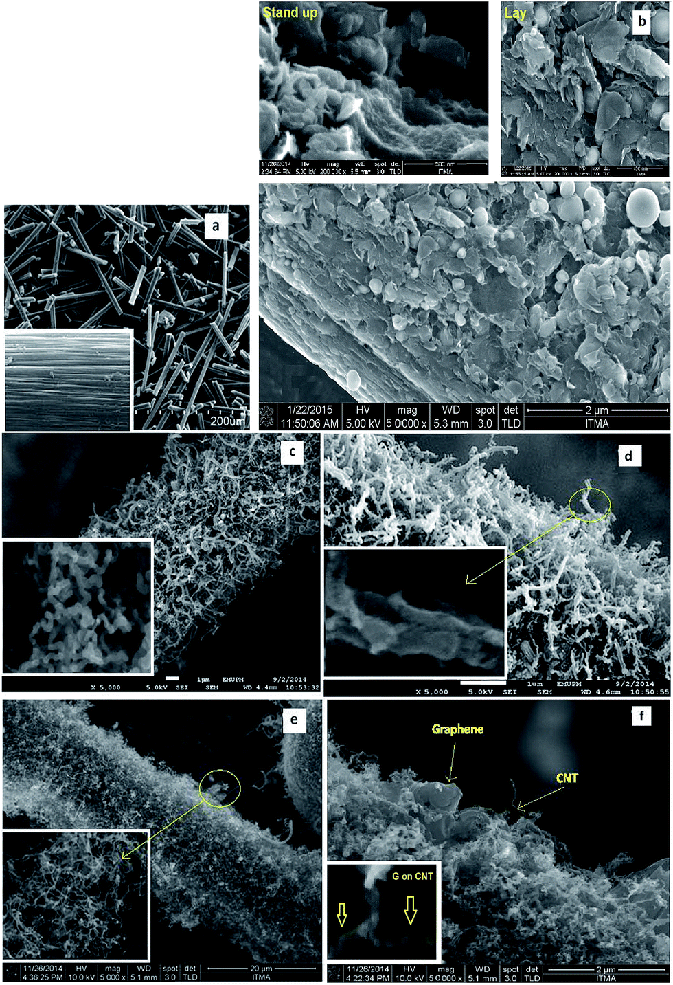 | ||
| Fig. 2 (a) SEM images of CF, FESEM images of (b) CF–G with two forms (stand up and lay), (c) CF–CNF, (d) CF–CNF–G, (e) CF–CNT and (f) CF–CNT–G. | ||
To capture the TEM images of the carbon nanoparticles (CNF, CNT, G), the sample was dispersed in an acetone solution in order to separate the nanoparticles from each other. The TEM images in Fig. 3(a) and (b) revealed the CNFs and CNTs with herringbone (150–250 nm) and tubular (50–100 nm) structures, respectively. The graphene sheets with 200–1000 nm widths are presented in Fig. 3(c) and (d). From Fig. 5(c), it can be found that the G flake was composed of a few graphene layers. The TEM images in Fig. 3(e) and (f) indicate that the graphene flakes not only adhered to the CNF and CNT but were also directly bonded to the CNF and CNT surfaces.
 | ||
| Fig. 3 TEM images of (a) herringbone structure of CNF (b) tubular shape of CNT, (c) sheet form of G, (d) CNF–G and (e) CNT–G. | ||
To acquire the surface activity of the resulting carbon nanoparticles on the carbon fiber, the BET-specific surface area was determined. The inserted graph in Fig. 4 shows the BET surface area of the carbon fiber with different modified CF, which changed from 0.7 to 46 m2 g−1.
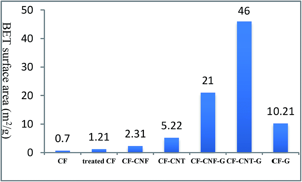 | ||
| Fig. 4 The BET surface area (m2 g−1) measurement of neat CF, treated CF and different carbon particles. | ||
The neat CF was immersed into a nitric acid solution (65%) for 5 h to modify its surface area. The surface area of the neat CF (0.7 m2 g−1) increased to 1.21 m2 g−1 for the treated CF. After that, by growing the different types of carbon nanomaterials on the treated CF, its surface area increased up to 46 m2 g−1. From the above explanation, it can be concluded that the effect of the carbon nanomaterial is more than the acidic treatment on the CF surface area.
According to this figure, the surface area of the carbon nanomaterials–CF was higher than the raw CF, which was due to the formation of carbon nanomaterials with different dimensions on the surface of the carbon fibers. The difference in the morphology and diameter of the carbon nanoparticles led to the differential surface activity to the carbonaceous matter present on the CF surface.81 It was found that among these carbon nanoparticles, the carbon nanofiber had the lowest surface area, which was modified by growing G on its surface. On the other hand, graphene flakes with high surface areas had a planar shape and 2D structure. As it was mentioned before, some G flakes lay on carbon fiber surface which can not cause to increase its surface area significantly, but when G is grown on CNF or CNT surface, it makes a 3D network and leads to increase the surface area meaningfully. Therefore, aligning carbon nanotubes with graphene flakes provided a well-organized and high surface area 3D geometry. Hence, the resultant CF–CNT–G with the highest surface area had the potential to be used as pioneer nanoparticles filler in the polymer composites.
X-ray diffraction (XRD) is a method of determining the arrangement of atoms within a crystal. The XRD data in Fig. 5 confirmed that the broad diffraction peak at the 20–30°, 2θ range was associated with the disordered carbon phases. Fig. 5 summarises the interlayer spacing, d002; crystalline height, Lc, determined by XRD; and crystalline width La (La = 4.4/R, R was the ratio of the integrated intensity of the D peak to the G peak, nm) from the Raman spectra.82 The growth of the graphene on the CNT–CF led to a decrease in d002 and an increase in Lc and La, which is indicative of the formation of a more ordered carbon structure. The results suggest that the order of the structure for all the samples increased with the presence of graphene with the carbon nanotubes because of the fact that CNT with the smaller diameter than CNF has the ability to be a substrate of the graphene flakes that leads to the most vertical graphene sheets on a tubular shape of the CNT having the most graphitisation structure.
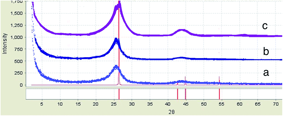 | ||
| Fig. 5 XRD of (a) CF–G, (b) CF–CNF–G and (c) CF–CNT–G. | ||
Raman spectroscopy is a fast, powerful and non-destructive method for structural characterization and quality information of carbon nanoparticles.83 In this article, various Raman features were studied including D peak (∼1350 cm−1), G peak (∼1580 cm−1) and 2D peak (∼2650 cm−1). The D and 2D bands provided information about the electronic and geometrical structure through the double resonance process. The D peak related to the breathing modes of the sp2 atom84 activated by the presence of any defect (e.g., lattice disorder,85 edges or functional groups86). The G peak is associated with an E2g stretching mode of the graphitic crystalline structure. The stretching of the C–C bond in graphitic materials gives rise to the G peak which is related to all sp2 carbon systems. The intensity ratio of the D peak and the G peak (ID/IG) was utilized to evaluate the degree of graphitization.86 The Raman spectra in Fig. 6 show a simple characterization of the resulting CNF, CNT, G on the CF surface and also their interaction with PP. Fig. 6(a–f) were taken from the CF surface, CF–CNF, CF–CNF–G, CF–CNT, CF–CNT–G and CF–G. The general sharpness of the bands and narrowness of the bandwidths were indicative of a relatively high structural order as the consequence of a high heat treatment.86 As expected, there were no significant radial breathing modes (RBM) in the range of 1200–1300 cm−1, which were unique for the graphene. In addition, the graphene and carbon nanotubes displayed a strong graphite mode or G band at about 1500 cm−1 and a much weaker defect-induced Raman band (defect mode or D band).87 Hence, the significant D peak observed for the carbon nanofiber and carbon nanotube was thought to possibly be the sp3-hybridized carbons in the nanofiber and nanotube walls88 or open end of these nanomaterials. Finally, where the 2D peak for the carbon nanotubes and graphene appeared, there were a strong, narrowband at about 2700 cm−1 and a weaker band at 2400 cm−1, which indicated highly graphitic crystalline structures.
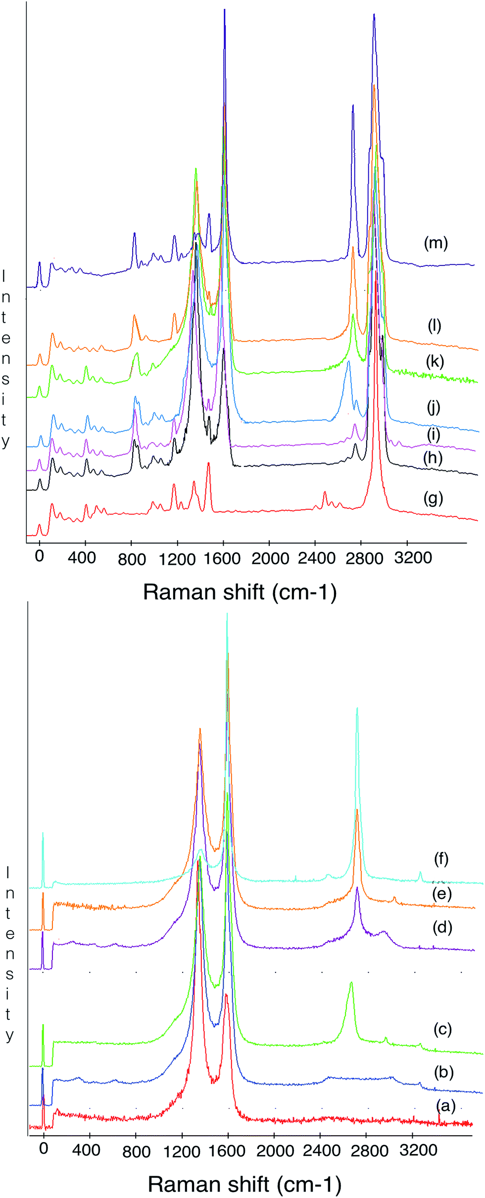 | ||
| Fig. 6 Raman spectroscopy of (a) CF, (b) CF–CNF, (c) CF–CNF–G, (d) CF–CNT, (e) CF–CNT–G, (f) CF–G particles and (g) PP, (h) CF/PP, (i) CF–CNF/PP, (j) CF–CNF–G/PP, (k) CF–CNT/PP, (l) CF–CNT–G/PP and (m) CF–G/PP composites. | ||
Moreover, Raman spectroscopy has been used to probe the interaction between the fillers and polymer in order to study the influence of the fillers on the mechanical behavior of the composite. To this end, the spectrum in Fig. 6(g–m) was taken from the PP, CF/PP, CF–CNF/PP, CF–CNF–G/PP, CF–CNT/PP, CF–CNT–G/PP and CF–G/PP samples. The interaction between the fillers and polymer matrix was reflected by a peak shift or a peak width change. From the spectra, it can be found that the peaks associated with the carbon nanoparticles were much stronger than the neat PP matrix; this was due to resonance and absorbance effects. So, these spectra confirm the interaction between the filler and PP matrix. The Raman bands of carbon nanoparticles are clearly observed in their composite spectra, but the PP ones do not appear because of their low intensity. To compare the CF–G/PP and CF–CNT–G/PP with other composites and also neat PP, it has been understood that the frequency of the G peak can be tuned by the mechanical properties of the filler.89 So, by growing the graphene on the carbon nanofibers and carbon nanotubes, the G and 2D peaks rose to a higher intensity which led to the increase in the interaction of these fillers with the polymer matrix, reflected by the vibrational dephasing of the macromolecular chains.
Mechanical and thermal test
According to Table 1 and Fig. 7, incorporating the carbon fiber with carbon nanoparticles increased the mechanical properties of the polymer matrix. Comparison of the stiffness of the composite fabricated from the graphene nanoparticles coated on the carbon fiber and CNT or CNF with neat CF illustrates a significant improvement in the tensile modulus. Contrarily, the tensile stress and young's modulus of the uncoated CF/PP were decreased which were related to the defective flow of the matrix around the neat carbon fiber that caused decreased interfacial properties, and was easily pulled out of the carbon fiber from the matrix.90 Similar to the stiffness, the strength of the CF–G/PP, CF–CNF–G/PP and CF–CNT–G/PP composites was higher than the CF/PP, CF–CNF/PP and CF–CNT/PP composites, respectively, because of the presence of G that led to the improvement of the stress transfer between the CF and the matrix.91 On the other hand, the presence of tubes with a high surface area in CF–CNT–G in comparison with CF–G and CF–CNF–G led to not only high interfacial adhesion with the polymer matrix but also the high strength of the resultant composite.| Samples | Tensile stress (MPa) | Increase (%) | Young's modulus (MPa) | Increase (%) |
|---|---|---|---|---|
| CF/PP | 30.5 ± 0.5 | — | 1603.7 ± 24.5 | — |
| CF–CNF/PP | 33.9 ± 0.8 | 11% | 1828.2 ± 30.5 | 14% |
| CF–CNF–G/PP | 36.6 ± 0.6 | 20% | 2100.8 ± 34.1 | 31% |
| CF–CNT/PP | 44.53 ± 0.1 | 46% | 2213.1 ± 43.1 | 38% |
| CF–CNT–G/PP | 55.51 ± 0.7 | 82% | 2998.9 ± 47.1 | 87% |
| CF–G/PP | 51.24 ± 0.8 | 68% | 2758.3 ± 49.8 | 72% |
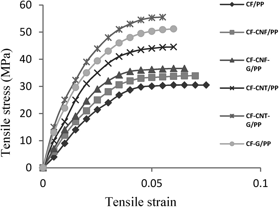 | ||
| Fig. 7 Graph of the tensile stress–strain of PP, CF/PP, CF–CNF/PP, CF–CNF–G/PP, CF–CNT/PP, CF–CNT–G/PP and CF–G/PP (with 5 wt% filler–95 wt% PP). | ||
The relationship between the mechanical properties of the composites and the reinforcement fillers has been calculated by mathematical models. One of an accepted and extensively adopted model to compute the stiffness of fiber/polymer composites is the Halpin–Tsai (HT) equation.92 The HT model correlates the stiffness of the composite with the tensile modulus of the matrix and reinforcement as well as its volume contents and geometry. Therefore, to calculate the tensile modulus of the composites with unidirectional or randomly distributed fibers this model has been used. Here, CF, CF–CNF, CF–CNT, CF–G, CF–ACNF–G and CF–CNT–G were considered as fillers with a random distribution in the polypropylene matrix. By considering the incorporation of G, CNT and CNF with CF reinforcements within the matrix, the HT equations were modified according to the following equation:93
 | (1-1) |
Then, the effective reinforcement modulus of the fillers was calculated as below:
 | (1-2) |
According to eqn (1-2), the Young's modulus of the various fillers was calculated and reported in Fig. 8, where Ec was collected from Table 1, Em was about 1400 MPa, Vf was 5% and Vm was 95%.
 | ||
| Fig. 8 Effective reinforcement modulus of the different fillers in the polypropylene matrix. | ||
It was found from Fig. 8 that the modulus of CF–CNT–G was higher than CF–G and this filler was higher than the other fillers. Such a meaningful difference was related to the presence of graphene as the strongest filler and also the tube shape of CNT, which had a good adhesion with the polymer matrix. By comparing the Young's modulus of the fibers, it can be deduced that the presence of the graphene flakes enhanced the tensile modulus, significantly. Besides that, the CNTs not only increased the surface area of CF but also made a towering forest with the PP matrix which led to the high interlocking with the polymer matrix. The difference in the effective reinforcement modulus between CF–CNT–G and CF–G was about 100 MPa, which was higher than the difference between CF–G and CF–CNT (300 MPa). Hence, the impact of the graphene layer was more than the tube shape of the carbon nanotubes to reinforce the polymer. Consequently, the mathematical calculations confirmed the experimental results of the tensile modulus of the fillers.
The fracture surfaces of the CF/PP, CF–CNF/PP, CF–CNT/PP, CF–CNF–G/PP, CF–CNT–G/PP and CF–G/PP composites were studied by use of the SEM micrograph in Fig. 9. From the images, it was found that the neat CFs with a smooth surface had minimal signs of any interfacial interaction with the polymer matrix. In the case of the CF–CNF/PP and CF–CNT/PP composites, as they were shown in Fig. 9(b) and (c), some interactions of the PP residue to the CF surface have appeared as indicated by the relatively rough surface of the fillers. The presence of great amounts of PP matrix on the CF surface is shown in Fig. 9(d)–(f) are proof of the enhanced adhesion between the fiber and the PP matrix. Such interaction can be interpreted as affecting the grafting of not only the carbon nanoparticles on CF but also the presence of G on the surface. Additionally, the micromechanical coupling of the fillers with the matrix was related to the effective PP matrix transfusion into the CNT and CNF on the CF surfaces, which led to a strong interlocking matrix with the fillers. By comparing the CF–G/PP and CF–CNT–G/PP or CF–CNT/PP, it was found that the presence of the G flakes was more important than CNT as a reinforcing factor but the CNT has a main role in the PP matrix as an interlocking factor with the polymer matrix.
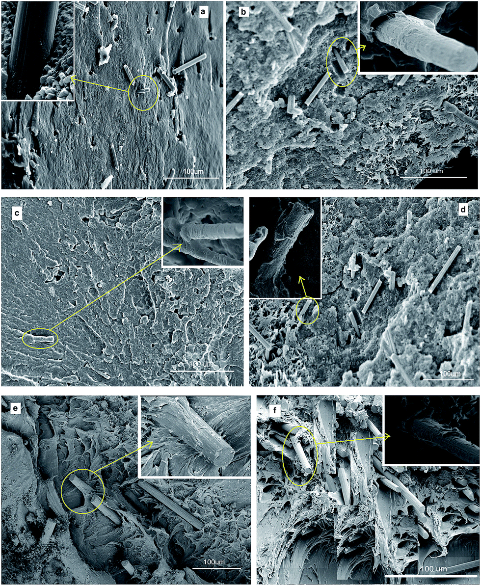 | ||
| Fig. 9 SEM images of the fractured surface of (a) CF/PP, (b) CF–CNF/PP, (c) CF–CNT/PP, (d) CF–CNF–G/PP, (e) CF–CNT–G/PP and (f) CF–G/PP. | ||
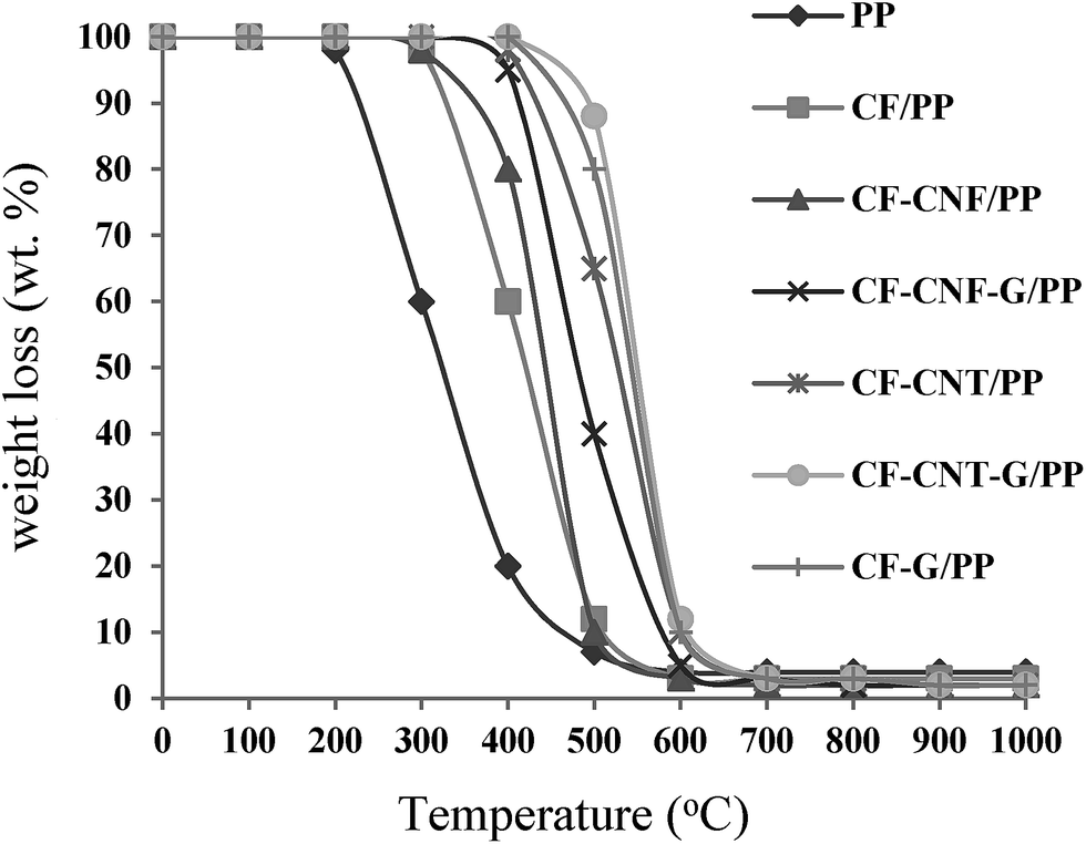
In the TGA process when the materials absorbed a certain amount of heat, a single degradation step for all samples and also thermal degradation began to occur.
The degradation process led to the breakdown of the matrix structure of the sample. The TGA curve demonstrates the TGA profiles of the samples according to the weight loss of the samples (%) versus temperature (°C).
The temperature where the weight loss exhibited 5 wt% was defined as the onset decomposition temperature (Tonset); the temperature at which the degradation rate reached a maximum was defined as Tmax. The TGA curves of the pure PP, CF/PP, CF–CNF/PP, CF–CNT/PP, CF–CNF–G/PP, CF–CNT–G/PP and CF–G/PP composites are illustrated in Fig. 10. The presence of the fillers, such as the CF, CNF, CNT and G layers, to the PP matrix caused an increase in the composite degradation temperature because of having a high heat absorption capacity. The neat PP decomposed rapidly from 200 to 400 °C and was exhausted at above 500 °C with no residual char left. The CF/PP composite lost weight at 350 °C; that was higher than the pure PP. On the other hand, the weight loss was related to the oxidation of the carbon nanoparticle layer coating on the CF which began to degrade around 400 °C and completely degraded around 750 °C. Hence, the mass losses at temperatures above 400 °C were related to the decomposition of the carbon nanoparticles while the mass losses below this temperature corresponded to the amorphous carbon materials.94
 | ||
| Fig. 10 TGA curves of the different composites. | ||
The CF–CNF/PP and CF–CNF–G/PP composites were evaluated by the mass losses during the TGA at temperatures from 380 °C to 500 °C and 450° to 590°, respectively. The CF–CNT–G/PP had a higher resistance than the CF–G/PP and it had more stability than the CF–CNT/PP. It could be generally seen that for the CF–CNT–G/PP and CF–G/PP samples, there were no changes in the weight of the samples until the temperature reached around 550 °C and 510 °C, respectively. Therefore, by using CF–CNT–G and CF–G as fillers in the polymer matrix, the thermal stability of the polymer composite was increased in comparison with the composites without G flakes.
Conclusion
Carbon nanofiber, carbon nanotubes and graphene were directly grown on CF to increase the surface area and strength of CF as filler in a polypropylene matrix to enhance the mechanical and thermal properties of the PP composite. Besides that, graphene flakes were fabricated on the surface of the resulting CF–CNF and CF–CNT to modify of the CF surface significantly. It has been found that the one-step CVD method was able to grow CNF–G and CNT–G on the CF surface by using a bimetallic catalyst (Ni/Cu). Growing of graphene flakes caused the increase of the surface area of its substrate which led to a robust network to increase the surface adhesion between the CF and the matrix. This led to the improvement of the properties of the polymer composites. This claim has been confirmed by the Raman spectroscopy spectra which were used to distinguish the carbon nanoparticles from each other. Also, Raman spectroscopy has been applied to evaluate the carbon nanoparticle/matrix interaction.In order to study the effects of the different types of fillers in terms of mechanical and thermal properties, the tensile test and TGA were performed on the CF/PP, CF–CNF/PP, CF–CNT/PP, CF–G/PP, CF–CNF–G/PP and CF–CNT–G/PP composites. Among the different fillers, the CF–CNT–G with the highest surface area and significant Raman spectra was used as a pioneer filler in the polymer, which caused the improvement of the mechanical and thermal properties. Since the CF–CNT–G/PP composites have strong structures, the tensile stress and Young's modulus of these composites compared to the neat CF/PP have increased 82% and 87%, respectively, which states the effects of graphitization on the surface of CF. According to the effective reinforcement, which was predicted by the mathematical model, it was found that not only the presence of the graphene but also the 3D network structures made by CNT have a main role to reinforce the polymer composites. In addition to that, the highest thermal degradation resistances which were related to the CF–G/PP and CF–CNT–G/PP increased about 150 °C and 200 °C, respectively, in comparison with the CF/PP.
Acknowledgements
The authors gratefully acknowledge the Universiti Putra Malaysia (UPM) for the financial support under the Exploratory Research Grant Scheme (ERGS).Notes and references
- K. Chrissafis and D. Bikiaris, Thermochim. Acta, 2011, 523, 1 CrossRef CAS PubMed.
- Y. Jia, K. Peng, X. Gong and Z. Zhang, Int J Plast, 2011, 27, 1239 CrossRef CAS PubMed.
- Q. Zhang, J. Liu, R. Sager, L. Dai and J. Baur, Compos. Sci. Technol., 2009, 69, 594 CrossRef CAS PubMed.
- H. Mahfuz, A. Adnan, V. K. Rangari, S. Jeelani and B. Z. Jang, Composites, Part A, 2004, 35, 519 CrossRef PubMed.
- F. Rezaei, R. Yunus, N. A. Ibrahim and E. S. Mahdi, Polym.-Plast. Technol. Eng., 2008, 47, 351 CrossRef CAS.
- S. Aziz, S. Abdul Rashid, S. Rahmanian and M. A. M. Salleh, Polym. Compos., 2014 DOI:10.1002/pc.23103.
- R. M. Novais, J. A. Covas and M. C. Paiva, Composites, Part A, 2012, 43, 833 CrossRef CAS PubMed.
- M. C. Paiva, R. M. Novais, R. F. Aráujo, K. K. Pederson, M. F. Proença, C. J. R. Silva, C. M. Costa and S. Lanceros-Méndez, Polym. Compos., 2010, 3, 369 Search PubMed.
- F. Ghaemi, A. Ahmadian, R. Yunus, M. A. M. Salleh and N. Senu, RSC Adv., 2015, 5, 9925 RSC.
- P. M. Ajayan, O. Stephan, C. Colliex and D. Trauth, science, 1994, 256, 1212 Search PubMed.
- G. Z. Chen, M. S. P. Shaffer, D. Coleby, G. Dixon, W. Zhou, D. J. Fray and A. H. Windle, Adv. Mater., 2000, 12, 522 CrossRef CAS.
- J. N. Coleman, U. Khan and Y. K. Gun'ko, Adv. Mater., 2006, 18, 689 CrossRef CAS.
- A. B. Dalton, S. Collins, E. Muñoz, J. M. Razal, V. H. Ebron, J. P. Ferraris, J. N. Coleman, B. G. Kim and R. H. Baughman, Nature, 2003, 423, 703 CrossRef CAS PubMed.
- S. Kumar, T. D. Dang, F. E. Arnold, A. R. Bhattacharyya, B. G. Min, X. Zhang, R. A. Vaia, C. Park, W. W. Adams, R. H. Hauge, R. E. Smalley, R. Ramesh and P. A. Willis, Macromolecules, 2002, 35, 9039 CrossRef CAS.
- A. A. Mamedov, N. A. Kotov, M. Prato, D. M. Guldi, J. P. Wicksted and A. Hirsch, Nat. Mater., 2002, 1, 190 CrossRef CAS PubMed.
- M. S. P. Shaffer and A. H. Windle, Adv. Mater., 1999, 11, 937 CrossRef CAS.
- A. Yu, H. Hu, E. Bekyarova, M. E. Itkis, J. Gao, B. Zhao and R. C. Haddon, Compos. Sci. Technol., 2006, 66, 1187 CrossRef PubMed.
- H. Mahfuz, A. Adnan, V. K. Rangari, M. M. Hasan, S. Jeelani, W. J. Wright and S. J. De Teresa, Appl. Phys. Lett., 2006, 88, 083119 CrossRef PubMed.
- E. Camponeschi, R. Vance, M. Al-Haik, H. Garmestani and R. Tannenbaum, Carbon, 2007, 45, 2037 CrossRef CAS PubMed.
- M. M. J. Treacy, T. W. Ebbesen and J. M. Gibsoj, Nature, 1996, 381, 6584 CrossRef.
- M. F. Yu, O. Lourie, M. J. Dyer, K. Noloni, T. F. Kelly and R. S. Ruoff, Science, 2000, 287, 637 CrossRef CAS.
- B. K. Teo, S. Kenneth, C. Singh, M. Chhowalla and W. I. Milne, Encyclopedia of nanoscience and nanotechnology, 2003, vol. 10, no. 1 Search PubMed.
- K. S. Novoselov, A. K. Geim, S. V. Morozov, D. Jiang, Y. Zhang, S. V. Dubonos, I. V. Grigorieva and A. A. Firsov, Science, 2004, 306, 666 CrossRef CAS PubMed.
- N. Jianbing, L. Mingtao, C. Wonbong, D. Liming and X. Zhenhai, Carbon, 2014, 67, 627 CrossRef PubMed.
- F. Du, D. Yu, L. Dai, S. Ganguli, V. Varshney and A. K. Roy, Chem. Mater., 2011, 23, 4810 CrossRef CAS.
- Y. Zhu, L. Li, C. Zhang, G. Casillas, Z. Sun and Z. Yan, et al., Nat. Commun., 2012, 3, 1 Search PubMed.
- Z. Yan, L. Ma, Y. Zhu, I. Lahiri, Z. Liu and M. G. Hahm, et al., ACS Nano, 2013, 7, 58 CrossRef CAS PubMed.
- S. Rahmanian, A. R. Suraya, R. N. Othman, R. Zahari and E. S. Zainudin, Mater. Des., 2015, 69, 181 CrossRef CAS PubMed.
- F. Ghaemi, A. Amiri and R. Yunus, Trends Anal. Chem., 2014, 59, 133 CrossRef CAS PubMed.
- R. Sengupta, M. Bhattacharya, S. Bandyopadhyay and A. K. Bhowmick, Prog. Polym. Sci., 2011, 5, 638 CrossRef PubMed.
- S. Stankovich, D. A. Dikin, G. H. B. Dommett, K. M. Kohlhaas, E. J. Zimney and E. A. Stach, Nature, 2006, 442, 282 CrossRef CAS PubMed.
- H. Qian, E. S. Greenhalgh, M. S. P. Shaffer and A. Bismarck, J. Mater. Chem., 2010, 20, 4751 RSC.
- S. Tiwari, J. Bijwe and S. Panier, Tribol. Lett., 2011, 42, 293 CrossRef CAS.
- S. Tiwari, J. Bijwe and S. Panier, J. Mater. Sci., 2012, 47, 2891 CrossRef CAS.
- J. Liang, M. C. Saha and M. C. Altan, Procedia Eng., 2013, 56, 814 CrossRef CAS PubMed.
- S. Lijima, Nature, 1991, 354, 56 CrossRef.
- M. Yudasaka, T. Komatsu, T. Ichihaabi, Y. Achiba and S. Lijima, J. Phys. Chem. B, 1998, 102, 4892 CrossRef CAS.
- L. Guadagno, M. Raimondo, V. Vittoria, L. Vertuccio, K. Lafdi, B. D. Vivo, P. Lamberti, G. Spinelli and V. Tucci, Nanotechnology, 2013, 24, 305704 CrossRef PubMed.
- J. Y. Gu, K. X. Li, J. Wang and H. W. He, Microporous Mesoporous Mater., 2010, 131, 393 CrossRef CAS PubMed.
- S. Rahmanian, S. A. Rashid, R. Zahari and E. S. Zainudin, Appl. Surf. Sci., 2013, 271, 424 CrossRef CAS PubMed.
- K. Raji, S. Thomas and C. B. Sobhan, Appl. Surf. Sci., 2011, 257, 10562 CrossRef CAS PubMed.
- B. S. Lee, H. S. Yang and W. R. Yu, Nanotechnology, 2014, 25, 465602 CrossRef PubMed.
- S. Stankovich, D. A. Dikin, G. H. B. Dommett, K. M. Kohlhaas, E. J. Zimney, E. A. Stach, R. D. Piner, S. T. Nguyen and R. S. Ruoff, Graphene-based composite materials, Nature, 2006, 442, 282–286 CrossRef CAS PubMed.
- D. Li, B. M. Muller, S. Gilje, R. B. Kaner and G. G. Wallace, Nat. Nanotechnol., 2008, 3, 101–105 CrossRef CAS PubMed.
- S. H. Liu and S. C. Zhao, Adv. Mater. Res., 2014, 875, 1590 CrossRef.
- S. Liu, Z. Zhou, Z. Lin, Q. Ouyang, J. Zhang, S. Tian and M. Xing, BMC Biochem., 2009, 10, 22 CrossRef PubMed.
- H. Shu, X. M. Tao and F. Ding, Nanoscale, 2015, 7, 1627 RSC.
- Z. Fan, C. Wu, J. Chen and S. Yi, Carbon, 2008, 46, 378 CrossRef PubMed.
- S. Zhu, C. H. Su, S. L. Lehoczky, I. Muntele and D. Ila, Diamond Relat. Mater., 2003, 12, 1825 CrossRef CAS.
- Z. G. Zhao, L. G. Ci, H. M. Cheng and J. B. Bai, Carbon, 2005, 43, 663 CrossRef CAS PubMed.
- F. Ghaemi, R. Yunus, M. A. M. Salleh, H. N. Lim and S. A. Rashid, Fullerenes, Nanotubes, Carbon Nanostruct., 2015, 23, 669 CrossRef CAS.
- X. Li, W. Cai, J. An, S. Kim, S. Nah and D. P. R. Yang, Science, 2009, 324, 1312 CrossRef CAS PubMed.
- C. Mattevi, H. Kim and M. Chhowalla, J. Mater. Chem., 2011, 21, 3324 RSC.
- A. Venugopal, J. Chan, X. Li, C. W. Magnuson, W. P. Kirk and L. Colombo, J. Appl. Phys., 2011, 109, 104511 CrossRef PubMed.
- D. A. C. Brownson and C. E. Banks, Phys. Chem. Chem. Phys., 2012, 14, 8264 RSC.
- Y. P. Hsieh, M. Hofmann and J. Kong, Carbon, 2014, 67, 417 CrossRef CAS PubMed.
- M. A. Davoodi, J. Towghi and A. Rashidi, Chem. Eng. J., 2013, 221, 159 CrossRef CAS PubMed.
- E. Kimmari, V. Podgursky, M. Simunin, E. Adoberg, A. Surženkov, M. Viljus, M. Hartelt, R. Wäsche, I. Sildos and P. Kulu, Surf. Coat. Technol., 2013, 225, 21 CrossRef CAS PubMed.
- T. Dikonimos Makris, L. Giorgi, R. Giorgi, N. Lisi and E. Salernitano, Diamond Relat. Mater., 2005, 14, 815 CrossRef CAS PubMed.
- C. M. Seah, S. P. Chai and A. R. Mohamed, Carbon, 2014, 70, 1 CrossRef CAS PubMed.
- A. Dahal and M. Batzill, Nanoscale, 2014, 6, 2548 RSC.
- K. Takahashi, K. Yamada, H. Kato, H. Hibino and Y. Homma, Surf. Sci., 2012, 606, 728 CrossRef CAS PubMed.
- Z. R. Robinson, P. Tyagi, T. M. Murray, C. A. Ventrice Jr, S. Chen, A. Munson, C. W. Magnuson and R. S. Ruoff, J. Vac. Sci. Technol., 2012, 30, 011401 CrossRef.
- W. Yan-li, W. Xu-jian, Z. Liang, Q. Wen-ming, L. Xiao-yi and L. Li-cheng, New Res. Carbon Mater., 2012, 27, 53 Search PubMed.
- G. P. Dai, M. H. Wu, D. K. Taylor, M. K. Brennamanc and K. Vinodgopal, RSC Adv., 2012, 2, 8965 RSC.
- J. E. An, G. W. Jeon and Y. G. Jeong, Fibers Polym., 2012, 13, 507–514 CrossRef CAS.
- C. C. Teng, C. C. M. Ma, Y. W. Huang, S. M. Yuen, C. C. Weng, C. H. Chen and S. F. Su, Composites, Part A, 2008, 39, 1869 CrossRef PubMed.
- M. Kawasumi, N. Hasegawa, M. Kato, A. Usuki and A. Okada, Macromolecules, 1997, 30, 6333 CrossRef CAS.
- M. K. Seo and S. J. Park, Chem. Phys. Lett., 2004, 395, 44 CrossRef CAS PubMed.
- M. S. Dresselhaus, G. Dresselhaus, K. Sugihara, I. L. Spain and H. A. Goldberg, Graphite fibers and filaments, Springer-Verlag, Berlin, 1988, vol. 5 Search PubMed.
- L. G. Cancado, M. A. Pimenta, B. R. A. Neves, G. Medeiros-Ribeiro, T. Enoki, Y. Kobayashi, K. Takai, K. Fukui, M. S. Dresselhaus, R. Saito and A. Jorio, Phys. Rev. Lett., 2004, 93, 047403 CrossRef CAS.
- M. S. Dresselhaus, G. Dresselhaus and P. C. Eklund, Science of fullerenes and carbon nanotubes: their properties and applications, Academic Press, San Diego, CA, 1996 Search PubMed.
- M. S. Dresselhaus, G. Dresselhaus, R. Saito and A. Jorio, Phys. Rep., 2005, 409, 47 CrossRef PubMed.
- R. Saito, G. Dresselhaus and M. S. Dresselhaus, Physical properties of carbon nanotubes, Imperial College Press, London, 1998, vol. 4 Search PubMed.
- L. M. Malard, M. A. Pimenta, G. Dresselhaus and M. S. Dresselhaus, Phys. Rep., 2009, 473, 51 CrossRef CAS PubMed.
- A. C. Ferrari and J. Robertson, Philos. Trans. R. Soc., A, 2004, 362, 2477 CrossRef CAS PubMed.
- F. Rezaei, R. Yunus and N. A. Ibrahim, Mater. Des., 2009, 30, 260 CrossRef CAS PubMed.
- ASTM D638, Standard test method for tensile properties of plastics, ASTM International, West Conshohocken, PA, 2010 Search PubMed.
- S. Y. Fu, B. Lauke, E. Mader, C. Y. Yue and X. Hu, Composites, Part A, 2000, 31, 1117 CrossRef.
- M. S. Vishkaei, M. A. M. Salleh, R. Yunus, D. R. A. Biak, F. Danafar and F. Mirjalili, J. Compos. Mater., 2010, 1 Search PubMed.
- I. A. Rashkovan and Y. G. Korabelnikovb, Compos. Sci. Technol., 1997, 57, 1017 CrossRef CAS.
- F. Tuinstra and J. L. Koenig, J. Chem. Phys., 1970, 53, 1126 CrossRef CAS PubMed.
- A. C. Ferrari and J. Robertson, Philos. Trans. R. Soc., A, 2004, 362, 2267 Search PubMed.
- L. G. Cancado, A. Jorio, E. H. Martins Ferreira, F. Stavale, C. A. Achete, R. B. Capaz, M. V. O. Moutinho, A. Lombardo, T. S. Kulmala and A. C. Ferrari, Nano Lett., 2011, 11, 3190 CrossRef CAS PubMed.
- A. C. Ferrari and D. M. Basako, Nat. Nanotechnol., 2013, 8, 235 CrossRef CAS PubMed.
- J. Y. Hwang, C. C. Kuo, L. C. Chen and K. H. Chen, Nanotechnology, 2010, 21, 465705 CrossRef PubMed.
- M. Endo, K. Nishimura, Y. A. Kim, K. Hakamada, T. Matushita, M. S. Dresselhaus and G. J. Dresselhaus, Mater. Res., 1999, 14, 4474 CrossRef CAS.
- J. L. Bahr, J. Yang, D. V. Kosynkin, M. J. Bronikowski, R. E. Smalley and J. M. J. Tour, J. Am. Chem. Soc., 2001, 123, 6536 CrossRef CAS PubMed.
- T. M. G. Mohiuddin, A. Lombardo, R. R. Nair, A. Bonetti, G. Savini, R. Jalil and A. C. Ferrari, Phys. Rev. B: Condens. Matter Mater. Phys., 2009, 79, 205433 CrossRef.
- S. Rahmanian, K. S. Thean, A. R. Suraya, M. A. Shazed, M. A. M. Salleh and H. M. Yusoff, Mater. Des., 2013, 43, 10 CrossRef CAS PubMed.
- R. J. Sager, P. J. Klein, D. C. Lagoudas, Q. Zhang, J. Liu, L. Dai and J. W. Baur, Compos. Sci. Technol., 2009, 69, 898–904 CrossRef CAS PubMed.
- J. C. Halpin and J. L. Kardos, Polym. Eng. Sci., 1976, 16, 344 CAS.
- M. A. Shazed, A. R. Suraya, S. Rahmanian and M. A. Mohd Salleh, Mater. Des., 2014, 54, 660 CrossRef CAS PubMed.
- E. Manseld, A. Kar and S. Hooker, Anal. Bioanal. Chem., 2010, 396, 1071 CrossRef PubMed.
| This journal is © The Royal Society of Chemistry 2015 |