
Au encapsulated into Al-MCM-41 mesoporous material: in situ synthesis and electronic structure†
Liangjie Fu‡
 ,
Chengli Huo‡,
Xi He and
Huaming Yang*
,
Chengli Huo‡,
Xi He and
Huaming Yang*
Centre for Mineral Materials, School of Minerals Processing and Bioengineering, Central South University, Changsha 410083, China. E-mail: hmyang@csu.edu.cn; Fax: +86-731-88710804; Tel: +86-731-88830549
First published on 13th February 2015
Abstract
Au supporting mesoporous material Al-MCM-41 composites were successfully prepared by encapsulation of the in situ synthesized gold nanoparticles into Al-MCM-41; herein palygorskite clay was used as the Si and Al sources and cetyltrimethylammonium bromide (CTAB) as the template and coupling agent. The obtained Al-MCM-41 possessed a well-defined two-dimensional hexagonal structure with a relative large specific surface area and pore size distribution of 3.9 nm, which was ideal to house very small Au nanoparticles (∼3 nm). Using this in situ encapsulation route, the highly ordered Al-MCM-41 was simultaneously generated with the gold nanoparticles incorporated into the pores and the Au3+ species well dispersed in the frameworks. The electronic structure and optical properties of Au/Al-MCM-41 were investigated in detail. The partial reduction of Au3+ species by incorporation of Al3+ from clay sources was confirmed by XPS results and DFT calculations, and the higher catalytic activities of Au/Al-MCM-41 over Au-MCM-41 were evaluated.
Introduction
Since the first discovery of mesoporous molecular sieves (M41S) in the 1990s, mesoporous materials have attracted widespread interest because of their unique characteristics, such as high surface areas, uniform pore sizes and distinct adsorption capacity.1,2 Moreover, it has been proved that the Al-containing mesostructured materials (Al-MCM-41) have relatively higher acidity and hydrothermal stability after the incorporation of Al into the framework of mesoporous structures.3,4 Consequently the ordered mesoporous Al-MCM-41 has been the focus of research due to its potential application in adsorption, ion exchange and catalysis. One of the intensive studies of mesoporous materials is encapsulation of heterogeneous species in their pore network, which can provide the composites with defined mesostructure and unique physical and chemical properties for varied application.5,6 So far, metal oxide, sulfide semiconductors, organic molecules and noble metal nanoparticles have been successfully incorporated into the pore-network of mesoporous silica materials for a variety of applications in catalysis, selective adsorption, chemical sensoring, separation science, and environmental control.7Noble metal nanoparticles (NPs) have been extensively studied because of their unique chemical and physical properties compared to bulk metals which make them suitable materials for potential applications in various fields.8 Gold in particular, have been found to play an important role in several catalytic processes including low-temperature CO oxidation, reductive catalysis of chlorinated and organic synthesis.9,10 It is deemed that the catalytic activity of Au nanoparticles is strongly related to its size, shape and surface charge. Both the experimental findings and theoretical predictions demonstrate that the particle size of Au plays a crucial role in governing its catalytic activity, and the optimum Au particle size must be smaller than 5 nm for essentially high catalytic activity.11 To date, several methods have been developed to prepare nanosized Au particles. However, the bare Au nanoparticles are difficulty separated from the reaction system and are also easily aggregate together in catalytic reactions due to high surface energy, thus resulting in a remarkable reduction of catalytic activities and impossible reusability.12 To overcome these disadvantages, gold NPs are usually immobilized in/onto solid supports, such as metal oxides, activated carbons, zeolites, mesoporous materials, and so on.13–16 Mesoporous materials are established to be one of the best candidates as a host matrix for obtaining and housing smaller gold NPs because of their adjustable pore sizes, pore architectures, and overall morphologies. For the supported Au catalysts, the catalytic activity at metal surfaces is related to both the electronic structure of the metallic surface and the interaction between metal NPs and the support.17 Although progress has been made recently in the preparation of supported Au catalysts, developing practical methods for the preparation of Au-based catalysts with good control of Au particle size and with high stability still remains a challenge.18
Two main approaches for the synthesis of mesoporous materials with noble metal nanoparticles located in the pores have been developed. The metal nanoparticles are encapsulated into the mesoporous support either by post-synthesis treatment, or by in situ technique.19 Metal incorporation post-synthesis is usually performed by various routes, including adsorption, ion-exchange, complexation, wetness impregnation, and covalent grafting.20 Generally, in the post-synthesis treatment the mesoporous materials surface requires to be functionalized with additives or surfactants to increase anchoring sites for guest species due to its inert surface. However, this often leads to formation of NPs lacking uniformity in size and shape. Furthermore, the interaction between the NPs and the support is often not strong enough, and agglomeration or leaching of the catalyst during the reaction is often observed. This is true in particular for noble metal catalysts.21 In contrast, the in situ incorporation is usually carried out by adding metal precursors to the synthesized silica gel before aging or by the stabilization of metal precursors inside the template micelles during the self-assembly of the surfactants and silica. Therefore, the direct incorporation method usually generates a high dispersion of metal nanoparticles and regular shapes and pores.22,23 Recently, several noble metals (Au, Pt, Ag) have been successfully incorporated into the mesoporous materials SBA-15 by an in situ reduction method. However, the mesoporous matrixes used in these work were mostly constructed by pure silica materials when using chemical salts as sources. Furthermore, the relative lager metal nanoparticles with average size around 7 nm were formed in the pores or on the external support surface, which were unfavorable for catalysis and also easily leached off from the support.24–26 Recently, clay-based photocatalysts have been synthesized by various methods, such as sol–gel, solution mixing,27 coprecipitation and hydrothermal method.28 However, to date, the fabrication of Al-containing mesoporous silica nanocages with smaller Au nanoparticles encapsulated and well-dispersed by a facile method using clay sources remains a challenge.
Herein, a facile one-step technique is proposed for the successfully synthesis of highly ordered Au/Al-MCM-41 using clay sources. In addition, to the best of our knowledge, the in situ encapsulation of gold nanoparticles inside mesoporous structures of Al-MCM-41 has not been reported yet. In this synthetic system, the highly dispersed and small gold nanoparticles were produced by citrate reduction of HAuCl4 during hydrothermal reaction, and the ordered mesopores of Al-MCM-41 were simultaneously generated, which could ensure the gold nanoparticles well-confined into the pores of Al-MCM-41.29 This design strategy has two advantages: (1) forming very tiny Au nanoparticles with average size around 2–3 nm; (2) stabilizing the Au nanoparticles against aggregation, which can guarantee a high catalytic property for gold nanoparticles. Furthermore, since the charge state of Au might vary due to implantation of Al into the frame of Au/Al-MCM-41 composite when the palygorskite clay was used as sources, the atomic-level interfaces between Au nanoparticles and Al-MCM-41 was discussed and the electronic structures of Au/Al-MCM-41 were given based on DFT calculations.
Methods
Materials synthesis
The Si and Al sources used for preparation Al-MCM-41 were fully derived from the leaching solution of palygorskite clay. For the typical synthesis of the gold nanoparticles encapsulated in the Al-MCM-41 with 2D hexagonal mesostructure, 10.0 g palygorskite clay (Jiangxu, China) and 15 g solid NaOH (Sinopharm Chemical Reagent Co., Ltd.) were first mixed and then heated at 600 °C for 2 h. Then, the mixture was dissolved in 400 mL deionized water stirred at room temperature for 16 h. The leaching solution was used as Si and Al sources without addition of Si or Al reagents. 1.0 g cetyltrimethylammonium bromide (CTAB, Sinopharm Chemical Reagent Co., Ltd.) and 1.0 g Polyethylenglycol4000 (PEG4000, Sinopharm Chemical Reagent Co., Ltd.) were dissolved completely in 50 mL of deionized water in 40 °C water bath. Then, 10 mL 0.1 g L−1 HAuCl4 (Sinopharm Chemical Reagent Co., Ltd.) solution with 10 mL of 0.1 g L−1 CTAB was added to the above solution, then 80 mL leaching solution was poured into the above solution under stirring. HCl (Sinopharm Chemical Reagent Co., Ltd.) solution (2 M) was added dropwise to adjust the pH value of the mixture to 10.0, the white mixture was stirred at 40 °C for 1 h in an water bath and then 0.6 g sodium citrate dissolved in 10 mL water was added into the white mixture, and then transferred into a Teflon-lined steel autoclave, statically heated at 110 °C for 24 h, and cooled to room temperature. The resultant product was filtered, washed and dried at 80 °C for 12 h to produce the as-synthesized sample. The sample was calcined at a heating rate of 2 °C min−1 to 550 °C and maintained at this temperature for 6 h to remove the template and produce the pink powder of Au/Al-MCM-41. The pure Al-MCM-41 mesoporous material was synthesized with the same method as comparison. The Al-free sample of Au/MCM-41 was synthesized using sodium silicate (Sinopharm Chemical Reagent Co., Ltd.) as Si source. For the typical synthesis of the Au/MCM-41 sample, 1.0 g CTAB and 1.0 g PEG4000 were dissolved completely in 50 mL of deionized water in 40 °C water bath. Then, 2.84 g sodium silicate was dissolved in above solution, and the following procedure was the same as the Au/Al-MCM-41 sample.Characterization
X-ray diffraction (XRD) patterns of the materials were collected on a D8 Advance Bruker diffractometer using CuKα radiation (λ = 1.5406 Å). Nitrogen gas adsorption–desorption isotherms were measured at 77 K using a Micromeritics ASAP 2020 Sorptometer. Prior to the adsorption, the samples were degassed in vacuum at 200 °C for 6 h. The Brunauer–Emmett–Teller (BET) method was utilized to calculate the specific surface area, the pore size distributions were calculated by Barrett–Joyner–Halenda (BJH) model from adsorption branches of the isotherms. The total pore volumes were estimated from the adsorbed amount at a relative pressure P/P0 of 0.99. The morphology of these samples were observed with a Transmission Electron Microscopy (TEM, JEOL JEM-2100F), fitted with an EDAX data analyzer, using 200 kV accelerating voltage. X-ray photoelectron spectroscopy (XPS) measurements were carried out on a Thermo Fisher Scientific K-Alpha 1063 spectrophotometer with the AlKα radiation. Ultraviolet-visible (UV-vis) spectrophotometry spectra were collected on a TU-1901 spectrophotometer at room temperature and the detection range of wavelength is from 190 nm to 700 nm. FTIR spectra of the samples were collected on a Nicolet Nexus 670 FTIR spectrometer using KBr discs in the range of 4000–400 cm−1.Catalytic properties experimental
Catalytic property was tested in a self-designed apparatus reported previously.30 Ortho-dichlorobenzene (o-DCB) was carried by air at a total volume space of 160 mL min−1, and the o-DCB was controlled with the concentration of 0.5 mg min−1 in air. Acetone was used as the absorption solution, and the catalyst powders were fixed on the ceramic honeycombs. Catalyst powders were uniformly dispersed in deionized water with a mass ratio of 1![[thin space (1/6-em)]](https://www.rsc.org/images/entities/char_2009.gif) :50, and were loaded into the pores of the ceramic honeycombs via impregnation. Then, the ceramic honeycombs were dried at 110 °C overnight before used in the catalytic activity test. After 60 min reaction at each temperature, quantitative analysis of o-DCB was performed using a GC-4000A with a flame ionization detector (FID).
:50, and were loaded into the pores of the ceramic honeycombs via impregnation. Then, the ceramic honeycombs were dried at 110 °C overnight before used in the catalytic activity test. After 60 min reaction at each temperature, quantitative analysis of o-DCB was performed using a GC-4000A with a flame ionization detector (FID).
Computational details
All calculations were performed with the program CASTEP (Cambridge Sequential Total Energy Package) code, based on first-principle density functional theory (DFT). Both the local density approximation (LDA) and generalized gradient approximation (GGA) with the exchange–correlation potential by Perdew, Burke and Ernzerhof (PBE), were used for the calculations.31 The ultrasoft pseudo-potential plane-wave formalism was applied for efficient computation. An energy cutoff of 400 eV was used. For the 3 × 3 × 3 supercell of SiO2 with 243 atoms, the Monkhorst–Pack grids with 2 × 2 × 2 k points were used for accurate calculation of the density of electronic states, whilst Gamma point was used for geometrical calculations. The self-consistent total energy in the ground state was effectively obtained by the density-mixing scheme. During the geometry optimizations, the convergence threshold for self-consistent field (SCF) tolerance was set to 1.0 × 10⁻⁶ eV per atom, all forces on the atoms were converged to less than 0.03 eV Å−1, the total stress tensor was reduced to the order of 0.05 GPa, and the maximum ionic displacement was within 0.001 Å. The valence states for O, Si, Al and Au were 2s22p4, 3s23p2, 3s23p1 and 5d106s1. The cell parameters and atomic coordination of the co-doped silica structures were optimized during the geometry optimization using a Broyden–Fletcher–Goldfarb–Shanno (BFGS) minimization algorithm.32Results and discussion
Small-angle XRD (SAXRD) patterns of pure Al-MCM-41 and Au/Al-MCM-41 in 2° < 2θ < 8° both show four peaks that can be indexed to (100), (110), (200) and (210) reflections of the two-dimensional hexagonal structure (P6m) characteristic of MCM-41 (Fig. 1a inserted), indicating that the host structure of the well ordered mesoporous Al-MCM-41 is well maintained after the encapsulation of Au nanoparticles inside its matrix. The minor shift of reflection peaks of Au/Al-MCM-41 to high angles compared with Al-MCM-41 accounts for the host framework contraction during Au formation. The slight decrease in peak intensity can be attributed to the pore-filling effect induced by gold nanoparticles encapsulating. Wide-angle XRD (WAXRD) pattern of pure Al-MCM-41 exhibits one broad peak from amorphous silica observed from 20° to 23° (Fig. 1a), whereas the Au/Al-MCM-41 shows (111) and (200) diffraction peaks in the range of 30° < 2θ < 50°, supporting the presence of gold nanoparticles in Au/Al-MCM-41. | ||
| Fig. 1 (a) Wide-angle XRD and small-angle XRD (inserted) patterns of samples; (b) pore-size distribution curves and N2 adsorption–desorption isotherms (inserted) of samples; (c) and (d) TEM images of Al-MCM-41 viewing along [100] and [110] direction respectively; (e) and (f) TEM images of Au/Al-MCM-41 viewing along [100] and [110] direction respectively; (g) TEM images of Au/Al-MCM-41 and the corresponding EDS spectra (inserted); (h) HRTEM images of the selected circle area in (g) and the structural model (inserted) of Au/Al-MCM-41. | ||
Nitrogen adsorption–desorption isotherm (Fig. 1b inserted) of Al-MCM-41 displays representative type-IV isotherms, suggesting the existence of well-developed mesoporosity formed by the removal of template. The Au/Al-MCM-41 sample retains the same isotherm shape but the amount of adsorbed nitrogen decreases and the onset of the capillary condensation step shifts to a smaller relative pressure. The decrease of the absorption amount can be attributed to the reduced surface area, whereas the shift of inflection point of the step to lower relative pressure P/P0 is caused by the smaller pore size. The pore size distribution curves (Fig. 1b) derived from adsorption branches using BJH model reveal the presence of relatively uniform mesopores in both samples. The BET surface area drops from 873.6 m2 g−1 of Al-MCM-41 to 706.5 m2 g−1 of Au/Al-MCM-41, while the pore volume and pore diameter decrease from 0.97 mL g−1 and 3.94 nm to 0.50 mL g−1 and 3.69 nm respectively (Table S1†). Consequently, it is reasonable that the gold nanoparticles are partially encapsulated into the pores of the mesoporous material, which can also be evidenced by the TEM characterization.
TEM images of the pure Al-MCM-41 sample (Fig. 1c and d) show a highly ordered mesoporous structure with long range order and regular two dimensional hexagonal pore structures. The inserted diffraction pattern in Fig. 1c clearly shows that the incident beam is along the [100] direction. In addition, the micrograph taken with the electron beam along the [110] shows the images of channels and the framework (Fig. 1d). TEM images of the Au/Al-MCM-41 (Fig. 1e and f) show that the highly ordered mesoporous structure is well-preserved after the incorporation of the Au nanoparticles into the channels of Al-MCM-41. Immobilization of Au nanoparticles on the Al-MCM-41 is clearly indicated that most of the gold nanoparticles synthesized by this pathway are well dispersed and intercalated into the channels of the mesoporous silica.33 Corresponding EDS spectra (Fig. 1g inserted) taken from the mesoporous composite confirm the presence of Au element on the mesoporous matrix. In these hexagonal structures, the average size of the Au nanoparticles obtained from the HRTEM image (Fig. 1h) is approximately 3 nm with a spherical shape. The structural model for Au/Al-MCM-41 is schemed in Fig. 1h by embedding a gold nanocluster in the mesoporous amorphous silica channel, with pore size of 4 nm. The measured lattice spacing is 0.235 nm, which can be assigned to the (111) plane of Au since no other crystalline materials exist in the composite.
The interfacial interactions of the samples were investigated by FTIR spectra and XPS analysis. The IR spectrum of Au/Al-MCM-41 is nearly unchanged after the incorporation of gold nanoparticles compared to the parent Al-MCM-41 (Fig. S1†), indicating that the structure of the support was well maintained after the incorporation of gold nanoparticles and which can also be confirmed the XRD and TEM observation. The vibration band at 3739 cm−1 is assigned as the asymmetry OH stretching vibrations of silanol groups located at the external surface of the mesoporous materials, while the absorption band observed at approximately 3434 cm−1 is attributed to the stretching vibrations of –OH units in the adsorbed water. The Si–OH deformational vibrations of adsorbed molecules produce the absorption band at approximately 1633 cm−1. The absorption band at 1082 cm−1, with a corresponding shoulder at 1233 cm−1 and a band at 756 cm−1, are assigned to the lattice of Si–O–Si stretching modes. The band at 967 cm−1 corresponds to the stretching vibrations of the surface Si–O groups, while the band at 461 cm−1 can be attributed to tetrahedral Si–O bending modes. After the incorporation of gold nanoparticles, the intensity of the band at 573 cm−1 are increased, which might be due to partial gold ions to be incorporated into the framework of Al-MCM-41.34
The surface chemical compositions and the oxidation state of the obtained Au/Al-MCM-41 sample were detected by XPS measurement (Fig. S2†). The Si, O, Al elements content derive from the surface of the Al-MCM-41 (Fig. S2a–c†). The high-resolution XPS spectrum of Au 4f region (Fig. S2d†) shows two peaks due to the Au 4f7/2 and to the Au 4f5/2 transitions. Both peaks exhibit asymmetric shapes, suggesting the presence of gold species with different oxidation state.35 The Au 4f7/2 and Au 4f5/2 peaks centered at 84.8 eV and 88.9 eV respectively with a spin–energy separation of 4.1 eV might be due to [AuCl2]−, which converted from [AuCl4]− during hydrothermal reaction. The sodium citrate is not strong enough to reduce [AuCl4]− to Au0 thoroughly when the [AuCl4]− was coupled by CTAB micelles in this reaction system.36 This also can be assigned to the oxidation of Au atoms due to the smaller particle size.37 The Au 4f7/2 and Au 4f5/2 peaks centered at 83.6 eV and 87.8 eV are characteristic of metallic gold, respectively. Compared with the Au 4f7/2 region recorded on the bulk Au atoms with a binding energy of 84.0 eV in other results, the obtained sample shows a slightly lower shift to the BE of 83.6 eV, this may be attributed to the formation of ultrafine Au particles (<5 nm) and the metal–support interaction.38,39 It should be mentioned that, in this Au/Al-MCM-41 sample, the Mg and other impurities of the natural material are removed by alkaline leaching, and only some of Al are left in the leaching solution, as evidenced by element analysis (Table S2†). Furthermore, the gold atoms are surrounded by Si/Al atoms, which will result in a decreased coordination number of surface atoms on the Au nanoclusters. For such a decrease in coordination number, the binding energy would shift to lower values relative to the bulk value, which is consistent with the previous results.40
From the discussion above, a schematic illustration of the one-pot deposition process of gold nanoparticles incorporated Al-MCM-41 is shown in Fig. 2. Firstly, the silicon and aluminum species were added into the CTAB solution when the template was dissolved completely, then the gold species AuCl4− coupled by CTAB was added dropwise into the precursor solution. When gold species AuCl4− was added into the CTAB solution, the AuCl4− can be trapped by CTAB via the electrostatic interaction because the amine groups of CTAB can bind to noble metal atoms through lone-pair electrons on nitrogen atoms.41 In this reaction system, the surfactant CTAB serves as a template as while as a coupling agent. The rods crystals were formed by the self-assemble of CTAB surfactant micelles after the silica species added in, and the silica precursors were adsorbed by the exterior hydrophilic polar groups. Simultaneously, the CTAB stabilized AuCl4− can be confined into the interior of the rod-like micelles crystals or the interface between the micelles. By this means, the coupled gold ions were encapsulated into the interspaces of the micelles after the silica precursors polymerized at the hydrophilic micellar interface. During the hydrothermal reaction, the ordered hexagonal array was established, and at the same time the gold nanoseeds were formed because of the reduction reaction between sodium citrate and gold ions. Due to the pore restriction effect, the gold nanoseeds were restrained to grow larger. Thereafter, the Au/Al-MCM-41 composites were obtained after calcination for removal of micelle template. Furthermore, calcination process would lead to the shrinkage of the mesostructures of the Al-MCM-41, which could restrict the gold nanoparticles growing further.
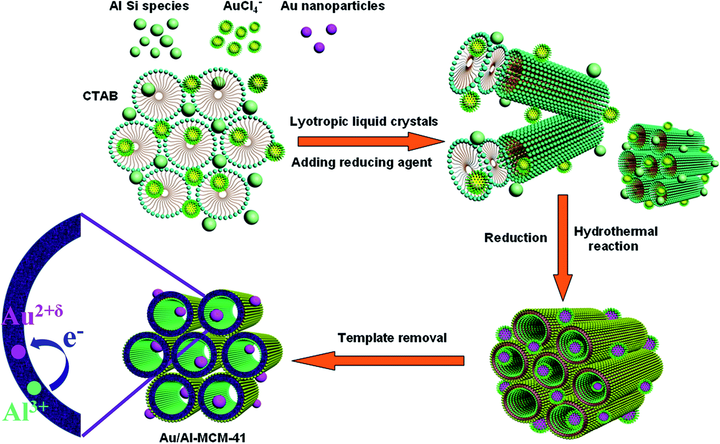 | ||
| Fig. 2 Proposed assembling mechanism for gold nanoparticles into the Al-MCM-41. | ||
Based on the XPS results, we can conclude that the bonding of Au with the support is complicated in Au/Al-MCM-41 structure and Au3+ species are partially reduced due to the incorporation of Al3+ in the support framework. Since Au might have valence state ranging from +0 to +3, the bonding of Au with the support is more flexible than Al. Thus, the Au–O bonds distort a little corresponding to the atomistic structure around the Au atom. The optimized Au–O bond lengths in Au/Al-MCM-41 range from approximately 1.8 Å to 2.3 Å, which was related to the rather disordered bonding system of MCM-41. Due to the larger atomic radius of Au over Al, the Au–O bond is much longer (0.2–0.3 A) than Si–O. The slight elongation of several Au–O bonds at one side of the structure makes Au atoms rather reactive, and enhances the catalytic properties.
It should be mentioned that the electronic calculations for rough amorphous structure with different kinds of reactive sites is a computational demanding task for DFT studies, as well as too complex for identifying the exactly influence of each component upon the experimental results. Hence, for simplicity, amorphous SiO2 is usually modeled by crystalline approximations in many studies.42–46 While GGA gave bond length of 1.61 Å, LDA calculations gave an average Si–O bond length of 1.59 Å as reported in our previous work.45 Whilst there were two distinct Si–O bonds with slightly different bond lengths in the bulk silica crystal, the Si–O bond lengths can be very close to 1.60 Å after full relaxation of slab model, consistent with previous work.46 Consider the heavy metal dopant of Au, in order to test the two functionals, we have compared the obtained DOS results for Au doped case. As shown in Fig. S3,† the LDA gives a little upshift for the whole valence band. Hence, the further discussions are based on PBE–GGA approximation.
The oxygen vacancy formation energy (EVO) is also investigated and calculated as follows:
| EVO = E(AlSi80O161) − [E(AlSi80O162) − E(O)] | (1) |
| EVO = E(AuSi80O161) − [E(AuSi80O162) − E(O)] | (2) |
| EVO = E(AuAlSi79O161) − [E(AuAlSi79O162) − E(O)] | (3) |
Although the formation energy of Au–Al co-doped silica with the Au and Al dopants adjacent to each other is about 1 eV lower than that with the dopants far from each other, for this study with one-pot synthesis method the later configuration is assumed the proper one. And, similarly, the formation of oxygen vacancy (VO) is preferred near the metal dopants as discussed in our previous work for doped alumina. As shown in Table 1, the formation of VO in silica is facilitated by Al, Au, and Au–Al doping due to the charge compensation effects, with the formation energy lowered by 3.95 eV, 1.25 eV and 0.72 eV. Furthermore, under the charge compensation effect, the charge of Au is decreased by co-doping with Al, which implies that the co-doping of Al3+ can oxidize Au2+ to Au2+δ after the easy formation of VO. Thus, based on above discussion, the variation of charge state of Au in Au/Al-MCM-41 (Fig. S2†) can be rationalized.
| VO formation energy | Au–O (Å) | Charge of Au (e) | Charge of Au (e) from XPS | |
|---|---|---|---|---|
| Al | 3.95 | — | — | — |
| Au | 1.25 | 2.215 | 1.30 to 0.95 | 2+ (ref. 31) |
| Au–Al | 0.72 | 2.129 | 1.31 to 1.68 | 2 + δ (this work) |
We first study the case the influence of metal doping on the electronic structure without introduction of intrinsic defects. As shown, Al doping slightly narrowed the band gap by about several hundred meV (Fig. 3a), while Au doping introduced several impurity Au states above Valance Band Maximum (VBM) (Fig. 3b). While the lower valence band is mainly O 2s states, the upper valence band is mainly O 2p states. The Al 3s, 3p states embed in the lower part of the conduction band and hybridized with Si 3s, 3p states. Thus, the O–Al bond in amorphous silica is assumed to be more ionic than that in alumina, which also implies the electrons donated by Al might be more delocalized. For Au doping case without VO, the Au atoms in silica structure are surrounded by Si4+ atoms, and the background compensation will force Au to its highest oxidation state of +3 (1.30 e), as shown in Table 1. For the case of co-doping, for Au and Al atoms are near each other or far from each other, the introduced states can be interpretated as hybrid states between Au and Al (Fig. 3c, near configuration) or simply as a combination of impurity states from above two dopants (Fig. 3d, far configuration). For near configuration, as seen from the charge density plot (Fig. 3e), the electrons are localized near Au dopants, forming some hybrid states with the Au 5d, 6s states above VBM and below the Conduction Band Minimum (CBM).
 | ||
| Fig. 3 The spin-polarized total density of states (DOS), atom-projected density of states (PDOS) of (a) Al-doped silica, (b) Au-doped silica, and Au–Al co-doped silica with the two dopants (c) near or (d) far from each other, a Gaussian broadening width of 0.1 eV was used. Partial charge density (e) corresponding to the states pointed by arrows in (c), the isosurface levels are 0.02 e Å−3. | ||
Due to the disorder in amorphous structure, there are plenty of oxygen vacancies caused by lattice distortion. The metal dopants, coupled with those inherent distorted oxygen in amorphous oxides, might form some novel species, introduce some hybrid defect states into the band structure, and possess higher photo excitation abilities.47 For Al doped case or Au doped case, the formation of VO around Al or Au dopant introduces some localized defect states in the middle of the silica band gap (Fig. 4a and b). And, besides the two Au-induced deep impurity states (brown), the hybrid states of Au 5d states and the O (bonded to Au) 2p states is formed at the VBM (yellow). However, in contrast to the Au doped case, the co-doping of Au and Al with the formation of VO near Au does not introduce deep impurity states but only narrow the band gap by introducing some hybrid states above valance band edge and below CBM (Fig. 4c), since the excess electron from VO is compensated by the Al atom at distance. As shown, the lower part of the conduction band is contributed by the SiO3 structure (the SiO4 with one oxygen removed) adjacent to Au, which is mainly Si 3p and O 2s, 2p states (purple). While the electron states introduced by the O atoms around Al (OAl) lead to the upward shift of the VBM, there is a hybrid state above VBM composed by mainly O 2p states and part of Au 5d states (brown). It should be noted that, in silica systems, while the oxygen deficiency and local charge density fluctuation around those distorted Si sites will introduce some defect states (i.e., VO states) in the band gap, however, the co-doping of Au and Al only narrows the gap, indicating that Au–Al co-doped silica might have better photocatalytic potential.
 | ||
| Fig. 4 The total density of states (DOS), atom-projected density of states (PDOS) of (a) Al-doped, (b) Au-doped and (c) Au–Al co-doped silica with an oxygen vacancy in each structure. Partial charge density corresponding to the states pointed by arrows are given for each structure, the isosurface levels are 0.02 e Å−3. | ||
From the electronic structure, optical properties of Au/Al-MCM-41 have been calculated (Fig. 5a), based on which the absorption bands in experimental UV-vis spectra (Fig. 5b) can be interpreted. Taking into account of a 20% underestimate of the PBE functional for d–d transitions, the DFT calculated results are in well agreement with experimental ones. The pure Al-MCM-41 shows some absorption peaks in the UV region and absorption band edge is red-shifted due to the introduction of VO under Al doping, as seen in Fig. 5a. For Au/Al-MCM-41 in this work, the blue shift of absorption edge of Au/Al-MCM-41 compared to Al-MCM-41 in this work or Au-MCM-41 in previous work48 is due to the electron transfer from Al dopants to the Au dopants (Au 5d states), and the visible light absorptions are attributed to excitation from ligand to the reactive Au2+δ ions in mesoporous framework, in addition to the surface plasmon resonance of gold clusters in the pore channels. The distinct absorption peak around 509 nm for Au/Al-MCM-41 (Fig. 5b) is attributed to the transverse mode of the surface plasmon absorption, suggesting the existence of Au nanoparticles on the silica matrix. It is reported that the wavelength of maximum absorption and the bandwidth of the plasmon resonance depend on the size and shape of the metal particles or aggregates on the substrates,49 and the gold nanoparticles with average 4 nm in diameter exhibit a UV-vis absorption spectrum with a band at 525 nm.50 The absorption band centered at 509 nm indicates that the average particle diameter of gold nanoparticles is less than 4 nm, as shown in TEM results. The inconspicuous absorption range from 350 nm to 450 nm might be due to the smaller Au nanoparticles.48
 | ||
| Fig. 5 (a) Calculated optical absorption for Al doped and Au–Al co-doped silica, with or without VO. (b) Experimental UV-vis absorption spectra of Al-MCM-41 and Au/Al-MCM-41. | ||
To compare the effect of Al-doping and Al-free on catalytic activities, the samples were used for the degradation of o-DCB. The catalytic activities of the samples at different temperature are shown in Fig. 6. The Al-MCM-41 exhibits no catalytic effect for the degradation of o-DCB, while Au/Al-MCM-41 and Au/MCM-41 show similar performance at relative lower temperatures (150–200 °C). However, at higher temperatures (200–300 °C), Au/Al-MCM-41 exhibits enhanced catalytic properties compared to Au/MCM-41. Hence, it is confirmed that while the Au3+ species in Au/Al-MCM-41 is partially reduced by the incorporation of Al3+ from clay sources, the much lowered formation energy of oxygen vacancy in this co-doping scheme has greatly improved the catalytic properties of Au/Al-MCM-41.
 | ||
| Fig. 6 Catalytic activities of various samples at different temperature for the decomposition of o-DCB. | ||
Conclusions
In summary, by using CTAB as template and coupling agent and palygorskite clay as the silicon and aluminum sources, the Au supporting mesoporous Au/Al-MCM-41 composite has been prepared hydrothermally through encapsulation of the in situ synthesized gold nanoparticles into the pores of the Al-MCM-41. XRD, HRTEM, N2 sorption, XPS, and UV-vis analysis were performed to characterize the composites, the results showed that the size of gold nanoparticles can be well controlled close to 3 nm using this in situ encapsulation route, which is known to be the optimum size for catalysis by gold. Mechanism study revealed that the gold ions (AuCl4−) was confined in interior of micelles and then reduced to gold nanoparticles by sodium citrate; meanwhile, the mesoporous Al-MCM-41 was generated simultaneously through polymerization of silicate precursors and CTAB micelles. Finally, combined with DFT calculations, the electronic structure and optical properties of Au/Al-MCM-41 were explored, and the atomic-level interfaces between the gold nanoparticles and the Al-MCM-41 support was also depicted. The Au and Al dopants were well dispersed in the mesoporous framework under one-pot synthesis method. While co-doping of Au and Al would facilitate the formation of VO near Au, the charge compensation of Al lead to the upward shift of VBM and the hybridization of VO states and Si 3p states would further narrow the band gap. The blue shift of absorption edges of Au/Al-MCM-41 compared to Au-MCM-41 is thus attributed to the charge compensation by Al from mineral source. Besides, while the Au3+ species is partially reduced by the incorporation of Al3+ from clay sources, the catalytic properties are found greatly enhanced. This approach can also provide a general route to encapsulate other metal nanoparticles into the pores of mesoporous silica, and the obtained composites could find a wide range of potential applications in the field of catalysis.Acknowledgements
This work was supported by the National Science Fund for Distinguished Young Scholars (51225403), the Hunan Provincial Natural Science Fund for Innovative Research Groups, the Specialized Research Fund for the Doctoral Program of Higher Education (20120162110079) and Hunan Provincial Innovation Foundation for Postgraduates (CX2011B120). All computations were performed at the High Performance Computing Center of Central South University.Notes and references
- C. T. Kresge, M. E. Leonowicz, W. J. Roth, J. C. Vartuli and J. S. Beck, Nature, 1992, 359, 710–712 CrossRef CAS.
- J. S. Beck, J. C. Vartuli, W. J. Roth, M. E. Leonowicz, C. T. Kresge, K. D. Schmitt, C. T. W. Chu, D. H. Olson and E. W. Sheppard, Journal of the American Chemical Society, 1992, 114, 10834–10843 CrossRef CAS.
- R. Mokaya, Adv. Mater., 2000, 12, 1681–1685 CrossRef CAS.
- C. Du and H. Yang, RSC Adv., 2013, 3, 13990 RSC.
- C. Wen, Y. Zhu, Y. Ye, S. Zhang, F. Cheng, Y. Liu, P. Wang and F. F. Tao, ACS Nano, 2012, 6, 9305–9313 CrossRef CAS PubMed.
- H. Yang, Q. Lu, F. Gao, Q. Shi, Y. Yan, F. Zhang, S. Xie, B. Tu and D. Zhao, Adv. Funct. Mater., 2005, 15, 1377–1384 CrossRef CAS.
- J. Shi, Chem. Rev., 2013, 113, 2139–2181 CrossRef CAS PubMed.
- S. Alayoglu, A. U. Nilekar, M. Mavrikakis and B. Eichhorn, Nat. Mater., 2008, 7, 333–338 CrossRef CAS PubMed.
- F. Lin and R. Doong, J. Phys. Chem. C, 2011, 115, 6591–6598 CAS.
- K. K. R. Datta, B. V. S. Reddy, K. Ariga and A. Vinu, Angew. Chem., Int. Ed. Engl., 2010, 49, 5961–5965 CrossRef CAS PubMed.
- L. Chen, J. Hu and R. Richards, J. Am. Chem. Soc., 2009, 131, 914–915 CrossRef CAS PubMed.
- F. Zhu, W. Wang and H. Li, J. Am. Chem. Soc., 2011, 133, 11632–11640 CrossRef CAS PubMed.
- M.-M. Wang, L. He, Y.-M. Liu, Y. Cao, H.-Y. He and K.-N. Fan, Green Chem., 2011, 13, 602 RSC.
- F. Cui, Z. Hua, C. Wei, J. Li, Z. Gao and J. Shi, J. Mater. Chem., 2009, 19, 7632–7637 RSC.
- Z. Bian, J. Zhu, F. Cao, Y. Lu and H. Li, Chem. Commun., 2009, 3789–3791 RSC.
- H. Jiang, B. Liu, T. Akita, M. Haruta, H. Sakurai and Q. Xu, J. Am. Chem. Soc., 2009, 131, 11302–11303 CrossRef CAS PubMed.
- G. Zhao, M. Ling, H. Hu, M. Deng, Q. Xue and Y. Lu, Green Chem., 2011, 13, 3088 RSC.
- W. Fang, J. Chen, Q. Zhang, W. Deng and Y. Wang, Chemistry, 2011, 17, 1247–1256 CrossRef CAS PubMed.
- N. Linares, E. Serrano, M. Rico, A. M. Balu, E. Losada, R. Luque and J. García-Martínez, Chem. Commun., 2011, 47, 9024–9035 RSC.
- L. Li, J.-L. Shi, L.-X. Zhang, L.-M. Xiong and J.-N. Yan, Adv. Mater., 2004, 16, 1079–1082 CrossRef CAS.
- J. Zhu, X. Xie, S. a. C. Carabineiro, P. B. Tavares, J. L. Figueiredo, R. Schomäcker and A. Thomas, Energy Environ. Sci., 2011, 4, 2020 CAS.
- E. Kockrick, L. Borchardt, C. Schrage, C. Gaudillere, C. Ziegler, T. Freudenberg, D. Farrusseng, A. Eychmüller and S. Kaskel, Chem. Mater., 2011, 23, 57–66 CrossRef CAS.
- X. Li, X. Liu, Y. Yang, J. Zhao, C. Li and Q. Yang, J. Mater. Chem., 2012, 22, 21045–21050 RSC.
- R. Veneziano, G. Derrien, S. Tan, A. Brisson, J.-M. Devoisselle, J. Chopineau and C. Charnay, Small, 2012, 8, 3674–3682 CrossRef CAS PubMed.
- C. Boissiere, D. Grosso, A. Chaumonnot, L. Nicole and C. Sanchez, Adv. Mater., 2011, 23, 599–623 CrossRef CAS PubMed.
- J. Han, P. Fang, W. Jiang, L. Li and R. Guo, Langmuir, 2012, 28, 4768–4775 CrossRef CAS PubMed.
- Y. Zhang, H. Gan and G. Zhang, Chem. Eng. J., 2011, 172, 936–943 CrossRef CAS PubMed.
- J. Liu and G. Zhang, Phys. Chem. Chem. Phys., 2014, 16, 8178–8192 RSC.
- I. Ojea-Jiménez and V. Puntes, J. Am. Chem. Soc., 2009, 131, 13320–13327 CrossRef PubMed.
- X. He, A. Tang, H. Yang and J. Ouyang, Appl. Clay Sci., 2011, 53, 80–84 CrossRef CAS PubMed.
- J. P. Perdew, K. Burke and M. Ernzerhof, Phys. Rev. Lett., 1996, 77, 3865–3868 CrossRef CAS.
- B. G. Pfrommer, M. Côté, S. G. Louie and M. L. Cohen, J. Comput. Phys., 1997, 131, 233–240 CrossRef CAS.
- R. Silva, A. V Biradar, L. Fabris and T. Asefa, J. Phys. Chem. C, 2011, 115, 22810–22817 CAS.
- M. Chatterjee, Y. Ikushima, Y. Hakuta and H. Kawanami, Adv. Synth. Catal., 2006, 348, 1580–1590 CrossRef CAS.
- E. Rombi, M. G. Cutrufello, C. Cannas, M. Casu, D. Gazzoli, M. Occhiuzzi, R. Monaci and I. Ferino, Phys. Chem. Chem. Phys., 2009, 11, 593–602 RSC.
- J. C. Yu, X.-C. Wang, L. Wu, W.-K. Ho, L.-Z. Zhang and G.-T. Zhou, Adv. Funct. Mater., 2004, 14, 1178–1183 CrossRef CAS.
- M. Pérez-Cabero, J. El Haskouri, B. Solsona, I. Vázquez, A. Dejoz, T. García, J. Álvarez-Rodríguez, A. Beltrán, D. Beltrán and P. Amorós, J. Mater. Chem., 2010, 20, 6780 RSC.
- Q. Fu, H. Saltsburg and M. Flytzani-Stephanopoulos, Science, 2003, 301, 935–938 CrossRef CAS PubMed.
- S. Minicò, S. Scirè, C. Crisafulli and S. Galvagno, Appl. Catal., B, 2001, 34, 277–285 CrossRef.
- H.-G. Boyen, G. Kästle, F. Weigl, B. Koslowski, C. Dietrich, P. Ziemann, J. P. Spatz, S. Riethmüller, C. Hartmann, M. Möller, G. Schmid, M. G. Garnier and P. Oelhafen, Science, 2002, 297, 1533–1536 CrossRef CAS PubMed.
- L. Vigderman, B. P. Khanal and E. R. Zubarev, Adv. Mater., 2012, 24, 4811–4841 CrossRef CAS PubMed.
- Y.-J. Kang, J. Kang and K. Chang, Phys. Rev. B: Condens. Matter Mater. Phys., 2008, 78, 1–5 Search PubMed.
- P. Shemella and S. K. Nayak, Appl. Phys. Lett., 2009, 94, 032101 CrossRef PubMed.
- T.-R. Shan, B. Devine, S. Phillpot and S. Sinnott, Phys. Rev. B: Condens. Matter Mater. Phys., 2011, 83, 1–8 Search PubMed.
- H. Yang, M. Li, L. Fu, A. Tang and S. Mann, Sci. Rep., 2013, 3, 1336 Search PubMed.
- S. Orlandini, M. Ippolito and L. Colombo, Phys. Rev. B: Condens. Matter Mater. Phys., 2010, 81, 1–8 CrossRef.
- L. Fu, X. Li, M. Liu and H. Yang, J. Mater. Chem. A, 2013, 1, 14592–14605 CAS.
- L. Chen, J. Hu, Z. Qi, Y. Fang and R. Richards, Ind. Eng. Chem. Res., 2011, 50, 13642–13649 CrossRef CAS.
- S. K. Ghosh and T. Pal, Chem. Rev., 2007, 107, 4797–4862 CrossRef CAS PubMed.
- M. Schulz-Dobrick, K. V. Sarathy and M. Jansen, J. Am. Chem. Soc., 2005, 127, 12816–12817 CrossRef CAS PubMed.
Footnotes |
| † Electronic supplementary information (ESI) available: The textural characteristics of the samples, element concentration analysis, FTIR spectra, XPS spectra of Au/Al-MCM-41, and the spin-polarized total density of states (DOS) for Au doped silica. See DOI: 10.1039/c5ra01701g |
| ‡ These authors contributed equally to this work. |
| This journal is © The Royal Society of Chemistry 2015 |