Intense UV upconversion through highly sensitized NaRF4:Tm (R:Y,Yb) crystals

Vishal Kale*a, Mika Lastusaaribc, Jorma Hölsäbcd and Tero Soukkaa
aDepartment of Biotechnology, University of Turku, Tykistökatu 6 A, FI-20520 Turku, Finland. E-mail: visoka@utu.fi
bDepartment of Chemistry, University of Turku, FI-20014 Turku, Finland
cTurku Centre for Materials and Surfaces (MatSurf), Turku, Finland
dInstituto de Química, Universidade de São Paulo, São Paulo-SP, Brazil

Received 27th January 2015 , Accepted 13th April 2015

First published on 13th April 2015


Abstract

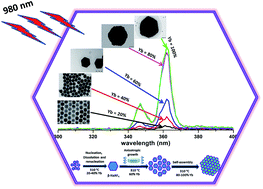
Photon upconverting luminescent hexagonal NaRF4:Tm (0.5 mol%) (R:Y3+,Yb3+) crystals with Yb3+ concentrations between 20 and 99.5 mol% were synthesized by a modified thermal coprecipitation method. The effects of the Yb3+ sensitizer concentration on the shape, size, structure, upconversion luminescence intensities and dynamic luminescence lifetimes were studied in detail. The intensity of ultraviolet upconversion luminescence at 340–365 nm upon 980 nm excitation increased up to 20 times with increasing Yb3+ concentration. The mechanisms for the changes in morphology, size and UV upconversion emission are discussed. In addition, the effect of the Tm3+ concentration on the UV emission of NaYbF4 crystals was investigated. The results demonstrate that the NaYbF4 with Tm3+ concentration between 0.4 to 0.8 mol% produce the most intense UV upconversion luminescence. These crystals may find applications in e.g. UV-visible solid state lasers or as an internal UV radiation source for many photochemical reactions.

Introduction

Lanthanides and rare earths have gained wide research interest during the last decades due to their unique electronic, magnetic, optical and chemical characteristics arising from the 4f electrons.1–3 Lanthanide-based photon upconversion (UC) has been known since the 1960's and photon upconverting nanoparticles (UCNPs) are already widely applied in many applications ranging from medical diagnostics to solar energy harvesting.4–11 Photon upconversion is a nonlinear optical process that converts the energy of two or more NIR photons into a single emitted photon at shorter wavelength (higher energy). Among the photon upconverting nanomaterials, hexagonal NaYF4 (β-NaYF4) nanocrystals have been intensively investigated as the most efficient upconversion host material available to date, because of their low phonon energy and the high quantum efficiencies obtained.12,13 It is known that also the nanocrystal size, structure, morphology and dopant ion concentration play crucial roles in the UC process.14–16 In general, the nanocrystal structure and size highly depend on the synthesis temperature, while commonly used organic additives act as shape modifiers to control the morphology of UCNPs. Currently, the research challenges comprise e.g. the optimal dopant ion combinations and understanding the behaviour of the relative intensities of different radiative transitions in luminescence spectrum of UC materials.

In recent years, ultraviolet (UV) UC photoluminescence has become one hot topic of optical functional materials. High energy UV emission is extremely important in many photochemical reactions in the field of chemical biology and advanced imaging.17–19 Intense UV emitting UCNPs are of special significance with potential technological applications in microelectronic devices and solid-state lasers.20 In our previous report, it was successfully demonstrated that UV emitting UCNPs can be used as an internal light source to form a shell with different functional groups around the particles to further facilitate their use in applications like bioassays, biosensing and theranostics.21 The main limitation for practical applications of upconversion materials is the insufficient upconversion efficiency; especially 980 nm excited UV UC photoluminescence remains challenging because it requires at least four NIR photons to populate the UV emitting excited states of Tm3+. Although NIR-excited UC to visible/NIR from NaYF4 with Er3+/Tm3+ and Yb3+ has been extensively studied, NIR-excited UC to UV is still less understood.22,23

UV UC properties in β-NaYF4 nanocrystals containing sensitizer Yb3+ and activator Tm3+ ions have been reported earlier.24 The doping concentration of lanthanide ions however seems to be very important in getting efficient UV UC emission.25 Recently, some researchers have focused their investigations on UV UC emission enhancement by doping with different ions or by a coreshell approach: e.g. Shen et al. have demonstrated the enhanced UV emission in CaF2 coated cubic NaYF4 (α-NaYF4) nanocrystals.26 Zeng et al. obtained higher UV emission from NaYbF4 microtubes compared to cubic NaYF4 nanocrystals27 and Zang et al. reported the deep-ultraviolet UC emissions from Gd3+ doped NaYF4:Yb,Tm nanorods.28 It should be noted that although there are a few strategies to enhance the UV emission from UCNPs, systematic studies of sensitizer concentration dependency of UV emission are scarce in literature.

In this work, a simple method is presented to increase the NIR to UV UC photoluminescence by replacing Y3+ from NaYF4:Yb,Tm crystals with Yb3+. The effect is investigated by stepwise increasing the sensitizer (Yb3+) concentration and optimizing the activator (Tm3+) concentration range for the NaYbF4 (xYb = 100%) host. In addition, the influence of different Yb3+ and Tm3+ concentrations on crystal size, shape, structure and optical properties such as UC luminescence intensity and decay lifetime were also investigated.

Experimental section

Reagents

All of the chemicals were of analytical grade and used as received without further purification. Yttrium, ytterbium and thulium chloride hexahydrate (RCl3·6H2O, 99.99%), ammonium fluoride (NH4F, ≥99.99%) and sodium hydroxide (NaOH, ≥98%), 1-octadecene (ODE, 90%) and oleic acid (OA, 90%) were purchased from Sigma-Aldrich. The purities of the rare earth chlorides are with respect to other rare earths. Absolute ethanol and methanol were used as received.

Material synthesis

Synthesis of NaY1−xYbxF4:Tm (0.5%). The synthesis protocol for the UCNPs was adopted from our previously published procedure.29 Briefly, the syntheses of 0.5% Tm doped NaY1−xYbxF4 UCNPs were done by stepwise substitution of Y3+ by 20, 40, 60, 80 and 100% of the sensitizer ion Yb3+ (the percentage of Yb3+ is with respect to the total rare earth contents excluding the activator). In a typical experiment, 0.2 mol dm−3 RCl3·6H2O (R:Y and/or Yb, Tm) in methanol were added to a 250 cm3 two neck round-bottom flask containing 9 cm3 oleic acid (OA) and 21 cm3 1-octadecene (ODE). The solution was magnetically stirred and heated to 160 °C under flowing argon for 40 min to form the rare earth oleate complex and then cooled down to room temperature. Thereafter, 15 cm3 of the methanol solutions of both NH4F (4.8 mmol) and NaOH (3 mmol) were added and the solution was stirred for 30 min without a protective gas sphere to evaporate methanol and to ensure that all the fluorides were consumed completely. The temperature was then increased to 310 °C and maintained there under argon for 90 min. After the solution was slowly cooled down to room temperature, absolute ethanol was added to the reaction solution to precipitate the nanocrystals. The solution was then transferred to the centrifuge tube and centrifuged at 3766 g for 8 min, so that the nanoparticles separated out completely. This washing procedure was repeated 6 times to ensure washing away any NaF impurity that may have formed. Finally, the nanoparticles were re-dispersed in toluene for further experiments.
Synthesis of NaYbF4:Tm (x%). Hexagonal NaYbF4:Tm (x%) were synthesized by replacing all Y3+ ions with the sensitizer Yb3+ ions and varying the activator ion (Tm3+) concentration (xTm = 0.05, 0.2, 0.4, 0.6, 0.8, 1 and 5%: the percentage of Tm3+ is with respect to the total rare earth contents). The synthesis and washing procedure is the same as that described for the NaY1−xYbxF4:Tm (0.5%) crystals. Finally, the nanoparticles were re-dispersed in toluene for further experiments.

Characterization

The size and morphology of the nanocrystals was characterized by transmission electron microscopy (Tecnai12 BioTwin TEM) with an acceleration voltage of 120 kV. The TEM specimens were prepared by directly drying a drop of a diluted toluene dispersion solution of the as prepared product on the surface of a carbon coated copper grid. The structural phase identification of the synthesized samples was carried out with X-ray powder diffraction (XPD) using a Huber G670 image plate Guinier camera (2θ range: 4–100°) with copper Kα1 radiation (λ: 1.5406 Å). Data collection time was 30 min with 10 scans of the image plate.

The crystallite size, shape and aspect ratio was calculated from the XPD data by using the Scherrer equation30 with instrumental correction from the full width at half maximum (FWHM) determined for a Si reference material (NIST standard 640b):

image file: c5ra01613d-t1.tif
where d (m) is the mean crystallite size, λ (m) the X-ray wavelength, β (rad) the FWHM of the chosen reflection and θ (°) half of the Bragg's angle (2θ). βr, βs and β are the reference, sample and corrected FWHM respectively. The (002) and (200) reflections were used for calculating the length of the hexagonal plates and the width of the hexagonal faces, respectively, thus giving the size and morphology of the crystallites.

The UC luminescence spectra were recorded on Varian Cary Eclipse fluorescence spectrophotometer (Varian Scientific Instruments, Mulgrave, Australia) equipped with a 980 nm laser diode module C2021-F1 (Roithner Lasertechnik, Vienna, Austria). The excitation power used in the experiment was 200 mW with a focusing area of approximately 2.4 mm2. The elemental composition was analysed by LEO 1530 Gemini scanning electron microscope with a Thermo Scientific UltraDry SDD X-ray detector (SEM-EDX).

Results and discussion

Phase identification and morphology

All synthesized materials showed well-defined strong and sharp reflections in their XPD patterns (Fig. 1), confirming the good crystallinity and purity of the products. For the phosphors, high crystallinity is important as it means less energy traps and strong luminescence. It has been reported that the hexagonal NaRF4 is a by far better host lattice for high UC emission than the cubic phase.31 All XPD patterns agreed well with the hexagonal NaYF4 reference pattern indicating that increased Yb3+ and Tm3+ concentrations did not induce phase transitions in the NaY1−xYbxF4:Tm (0.5%), and NaYbF4:Tm (x%) crystals.32
image file: c5ra01613d-f1.tif
Fig. 1 XPD patterns of hexagonal NaY1−xYbxF4:Tm (0.5%) with different concentrations of Yb3+ (top) and NaYbF4:Tm (x%) crystals with different concentrations of Tm3+ (bottom), along with a reference pattern calculated with PowderCell33 based on structural data reported.32 The additional reflections are the traces of * sodium chloride (NaCl) and § cubic NaRF4 impurities.

The shape and size of the synthesized crystals were further characterized with transmission electron microscopy (TEM). Fig. 2 shows the typical TEM images of as prepared NaY1−xYbxF4:Tm (0.5%) with different concentrations of Yb3+: (a) 20, (b) 40, (c) 60, (d) 80, (e) 100% and NaYbF4:Tm (x%) crystals with different concentrations of Tm3+: (f) 0.05, (g) 0.2, (h) 0.4, (i) 0.6, (j) 0.8, (k) 1 and (l) 5%. The increase or decrease in rare earth ion concentrations with respect to each other does not affect the crystal structure, while in case of crystal size and shape the Yb3+ and Y3+ concentrations play a vital role. UCNPs with Yb3+ concentration up to 40% have small spherical shape which changes to hexagonal plate when Yb3+ concentration is increased further. On the other hand increase or decrease in the Tm3+ ion concentration up to 0.6% keeps the particle size unaffected but further increase in the activator concentration gives also small UCNPs as a byproduct.


image file: c5ra01613d-f2.tif
Fig. 2 TEM images of hexagonal NaY1−xYbxF4:Tm (0.5%) with different concentrations of Yb3+: (a) 20, (b) 40, (c) 60, (d) 80, (e) 100% and NaYbF4:Tm (x%) crystals with different concentrations of Tm3+: (f) 0.05, (g) 0.2, (h) 0.4, (i) 0.6, (j) 0.8, (k) 1 and (l) 5%.

As one can see from the TEM images, at low sensitizer ion concentration, β-NaYF4: 20% Yb, 0.5% Tm nanoparticles appear nearly spherical in shape and monodisperse. The average diameter of the 20% Yb3+ doped nanoparticles is around 25 nm (Fig. 2a). When the Yb3+ concentration increased further to 40%, the particles grew up to 90 nm in all directions, keeping the spherical shape unchanged (Fig. 2b). At medium Yb3+ ion concentration, hexagonal plates with sharp edges can be prepared, which is shown in Fig. 2c and the average diameter calculated is about 150 nm. When the experiment is performed at 80% Yb3+ concentration, most of the Y3+ ions are already replaced by Yb3+ resulting in bigger hexagonal plates with a diameter of about 900–950 nm, which are basically polycrystalline plates made up from many small plates (Fig. 2d) as indicated by the Scherrer calculations. In the case of the NaYbF4:Tm (0.5%) crystals, where all Y3+ was replaced by Yb3+, the biggest polycrystalline hexagonal plates of about 1000 nm are formed (Fig. 2e). According to the Scherrer calculations, these are also polycrystalline. The low resolution TEM images showing homogeneity and size distributions of the particles are presented in the ESI, Fig. S6.

For the NaYbF4 crystals with different Tm3+ ion concentrations, the shape and size of the particles remains the same until the 0.6% Tm3+ doping level, the average diameters of all hexagonal plates being between 1000 and 1200 nm (Fig. 2f–i). The Tm3+ ion concentration of 0.8% induces the formation of small spherical particles along with the bigger hexagonal plates. The diameter of the large plates is about 750–800 nm and that of the small particles is up to 10 nm (Fig. 2j). The SEM-EDX analysis of both small and large particles shows that the elemental composition is the same in both size fractions (results of 0.8% Tm3+ sample are presented in the ESI, Fig. S5). For small particles, the Tm3+ is not detectable by the instrument as the concentration of Tm3+ is very small in the sample. A further increase in the Tm3+ concentration results in an increase in the population of small particles with about 25 nm in diameter along with few large hexagonal plates of about 900 nm (Fig. 2k and l). The effect of the Yb3+ and Tm3+ concentrations on the crystal size, shape and structure are listed in Tables 1 and 2.

Table 1 Summary of the morphologies, structure and dimensions obtained with TEM for the NaY1−xYbxF4:Tm (0.5%) crystals
Yb3+ (mol%)a Y3+ (mol%)a Structure Morphology Size
a The percentages are with respect to the added quantity in the synthesis.
20 80 Hexagonal Nanosphere 25
40 60 Hexagonal Nanosphere ≈90
60 40 Hexagonal Hexagonal plates ≈150
80 20 Hexagonal Hexagonal plates 900–950
100 0 Hexagonal Hexagonal plates 950–1000 and ≈20


Table 2 Summary of the morphologies, structure and dimensions obtained with TEM for the NaYbF4:Tm (x%) crystals
Tm3+ (mol%)a Structure Morphology Size
a The percentages are with respect to the added quantity in the synthesis.
0.05 Hexagonal Hexagonal plates ≈950
0.2 Hexagonal Hexagonal plates ≈1000–1200
0.4 Hexagonal Hexagonal plates 900–950
0.6 Hexagonal Hexagonal plates 900–950
0.8 Hexagonal Hexagonal plates 800 and ≤10
1 Hexagonal Hexagonal plates 900 and ≈25
5 Hexagonal Hexagonal plates 900 and ≈25


Crystal growth mechanisms

The experimental results show that the substitution of Y3+ in the host lattice by Yb3+ has a clear effect on the particle morphology and size. To investigate the formation process the sensitizer concentrations of NaY1−xYbxF4:Tm (0.5%) were increased stepwise by keeping all other synthesis parameters constant.

Regarding the growth mechanism, it is important to consider also the relation between the reaction temperature, initially formed crystals and the role of the chelating agent. It is known that the reaction temperature plays a crucial role in the α → β phase transition of NaYF4 and also the concentration of Yb3+ embedded in NaYF4 matrix affects the temperature of the phase transition in such a way that the temperature decreases with increasing the Yb3+ content.34 In the present work, 310 °C used is quite high for NaRF4 with high Yb3+ content and this results in large particles. Fig. 3 shows the possible formation mechanism for the β-NaRF4:Tm crystals with different Y/Yb concentrations.


image file: c5ra01613d-f3.tif
Fig. 3 Schematic representation of formation procedure of β-NaRF4,Tm (0.5%) with different Yb3+ concentrations. Inset is the schematic diagram showing the anisotropy of the β-NaRF4 crystals.

In the actual process, after dissolution and renucleation the unstable α-NaRF4 phase is transformed to the stable β-NaRF4. As the Yb3+ concentration in the reaction mixture increases the formation of the initial β-NaRF4 crystals will be faster and there is more time for crystal growth. This is because the increased Yb3+ concentration lowers the phase transition temperature.35 The nanocrystal formation mechanism for the UCNPs with 20 and 40% Yb3+ is a one step process and the phase transition from α → β was completed somewhat below 310 °C, which finally gives uniform 25 and 90 nm nanocrystals respectively (Fig. 3a and b). At these lower Yb3+ concentrations the growth rates in all directions are comparable which results in the spherical shape.

For the 60, 80 and 100% Yb3+ samples, the α → β phase transformation is completed well below 310 °C. As the initially formed β-NaRF4 has the hexagonal shape with an anisotropic structure, the crystal growth is anisotropic, as well. The hexagonal structure has four axes; three assistant axes intersecting each other at 60 degrees and one principle axis perpendicular to the hexagonal (001) crystal surface (Fig. 3, inset).36,37 The growth mechanism of the crystal depends on the growth rates along the different crystal axes which results into the different shapes of the final crystals. Once the hexagonal β-NaRF4 is formed, the oleic acid (OA) starts to show its influence as shape modifier. OA strongly reacts with the top/bottom (001) surfaces of the growing crystallites and lowers their surface energy, which results into the fast growth along the assistant axes rather than the principle axis. For the 60% Yb3+ sample, this anisotropic growth results into 130–150 nm hexagonal nanoplates (Fig. 3c). For the 80 and 100% Yb3+ samples, the temperature during the second heating may assist the formed hexagonal plates to self-assemble and anneal into the larger hexagonal polycrystalline structures with about 1000 nm size (Fig. 3d and e). This hypothesis of self-assembly of the nanoplates into larger polycrystals was supported by the calculations of diffracting domain sizes from the XPD patterns (Table 3). The data shows that, for the 80 and 100% Yb3+ samples, the hexagonal particles formed at the end of reaction are polycrystalline made up by aggregation of 130–150 nm nanoplates.

Table 3 Summary of decay times from the emitting 3H4, 1G4 and 1D2 level of NaY1−xYbxF4:Tm (0.5%) and NaYbF4:Tm (x%) with width to length (W/L) ratio and morphology calculated with the Scherrer methoda
NaY1−xYbxF4:Tm (0.5%) x mol%# W (nm) L (nm) W/L Morphology Decay times (μs)§
3H43H6 1G43H6 1D23H6
a Note: * the crystals are too large for Scherrer method, which commonly can treat sizes up to 150 nm, § the decay time with the highest amplitude in case of multiexponential decay, # the percentages are with respect to the added quantity in the synthesis.
20 27 24 1.12 Spherical 630 ± 8 576 ± 2 168 ± 0.3
40 30 28 1.04 Spherical 422 ± 5 547 ± 2 142 ± 0.3
60 53 34 1.55 Hexagonal plate 378 ± 7 224 ± 2 138 ± 0.3
80 56 35 1.59 Hexagonal plate 440 ± 5 362 ± 2 157 ± 0.4
100 149 79 1.89 Hexagonal plate 375 ± 1 293 ± 4 137 ± 0.3

NaYbF4:Tm (x%) x mol%# W (nm) L (nm) W/L Morphology Decay times (μs)§
3H43H6 1G43H6 1D23H6
0.05 212* 104 2.04 Hexagonal plate 481 ± 4 510 ± 5 272 ± 1
0.2 117 68 1.72 Hexagonal plate 470 ± 5 427 ± 0.5 235 ± 2
0.4 92 70 1.31 Hexagonal plate 430 ± 7 358 ± 1 169 ± 0.5
0.6 125 89 1.40 Hexagonal plate 321 ± 5 256 ± 3 125 ± 76
0.8 146 115 1.27 Hexagonal plate 337 ± 2 169 ± 2 98 ± 0.2
1 1011* 95 Hexagonal plate 275 ± 2 148 ± 0.5 82 ± 0.3
5 325* 162 Hexagonal plate 70 ± 0.5 82 ± 3 80 ± 10


Upconversion luminescence properties

To investigate the optical properties, the UC photoluminescence of colloidal NaY1−xYbxF4:Tm (0.5%) and NaYbF4:Tm (x%) crystals (0.1 mg ml−1 suspension in oleic acid) was measured under 980 nm diode laser excitation. As shown in the Fig. 4a and b, six UC photoluminescence lines were clearly resolved, centered at 346, 365, 450, 475, 649 and 800 nm, which correspond to the 1I63F4, 1D23H6, 1D23F4, 1G43H6, 1G43F4, and 3H43H6 transitions of Tm3+, respectively (non-normalized intensity spectra are in the ESI, Fig. S1 and S4). The weak emission at 511 nm arises from the transition of 1D23H5 and the lines at 690 and 720 nm correspond to the second order of 345 and 365 nm.38
image file: c5ra01613d-f4.tif
Fig. 4 Upconversion luminescence spectra of colloidal (a) NaY1−xYbxF4:Tm (0.5%) (xYb = 20, 40, 60, 80 and 100%) and (b) NaYbF4:Tm (x%) (xTm = 0.05, 0.2, 0.4, 0.6, 0.8, 1 and 5%) crystals under 980 nm excitation in oleic acid suspension, normalized at the emission peak of 800 nm. The inset shows the intensity variation of all major emissions as a function of (a) Yb3+ and (b) Tm3+ concentrations.

The energy levels of Yb3+ and Tm3+ ions as well as the proposed UC pathways under excitation at 980 nm are shown in Fig. 5. After 980 nm excitation, the sensitizer ion Yb3+ transfers energy to the neighbouring Tm3+ ions. Three successive energy transfers from Yb3+ to Tm3+ populate the 3H5, 3F2 and 1G4 levels of Tm3+. These energy transfer processes along with some non-radiative relaxation are responsible for the emissions at 475, 650, 690 and 800 nm. In the samples with lower Tm3+ content (0.05%) the simple piling of NIR photons (black thick arrows shown in the Fig. 5) is the only way to populate the 1D2 level. It is however not a very efficient process, because of the large energy mismatch between the energy difference of the 1D2 and 1G4 levels and the NIR photon energy. In the samples with Tm3+ content up to 0.8%, the cross relaxation 3F2 + 3H43H6 + 1D2 between the two Tm3+ ions plays an important role in populating the 1D2 level. The radiative relaxation from the 1D2 level gives the 365 and 450 nm emissions. Further increase in Tm3+ concentration, however, results in the depopulation of the higher emitting levels due to self-quenching. The Tm3+ ions in the 1D2 level can be excited to the 3P2 level by the fourth energy transfer mechanism from Yb3+ ions which relax rapidly to the 1I6 level giving another UV band centered at 346 nm.


image file: c5ra01613d-f5.tif
Fig. 5 Energy level diagrams of the Yb3+ and Tm3+ ions as well as the proposed UC mechanism for UV and visible emissions along with quenching mechanism by cross relaxation.

To increase the efficiency of the UV UC photoluminescence, we gradually increased the amount of the sensitizer ions (Yb3+), replacing Y3+ in the host material. As seen from the Fig. 4a, in hexagonal NaY1−xYbxF4 crystals with fixed Tm3+ concentration at 0.5%, all the emission intensities were increased stepwise along with the increase of the concentration of Yb3+ from 20% to 100%. The maximum UV emission was observed with 100% Yb3+ and the UC intensities at 346 and 365 nm emissions were measured to be about 20 and 18 times higher than that of the 20% Yb3+ sample, respectively. Along with the increase in the UV emission, the visible emission centered at 450 nm was also increased 30 times. The enhancement in the UV and visible emissions partially come from the fact that, with higher Yb3+ concentration the particle size increases, which decreases the surface to volume ratio. This decreases the amount of surface quenching centers and thus facilitates the high UC emission. The increased particle size, however, does not explain the whole enhancement mechanism as the decrease in surface to volume ratio after ≈150 nm particle size has no such strong influence on the UC spectra as reported before.39 Along with particle size there are thus other important factors which contribute to the intense UV and visible emissions. The increased Yb3+ concentration (keeping Tm3+ concentration fixed at 0.5%) increases the sensitization by absorbing more NIR photons and enhances the Yb-to-Yb energy migration as well as the Yb-to-Tm energy transfer probabilities, which leads to the increase of the population at 1I6 and 1D2 levels of the Tm3+ ions. The inset of Fig. 4a shows the variation of the different emission intensities as a function of Yb3+ concentration. Increasing the Yb3+ concentration beyond 60%, resulted in only small enhancement of the 475 and 800 nm emissions (4.5 and 2.7 times compared to 80% and 20% Yb samples) is observed. The increased sensitization by Yb3+ and the higher probability of energy migration due to shorter Yb-to-Yb distances can increase the probability of UV emission from Tm3+ which can ultimately result in the saturation of the emission from the lower emitting levels.26

The effect of the Tm3+ concentration on UV photoluminescence for the NaYbF4 crystals was also investigated using the UC emission spectra of NaYbF4:Tm (xTm = 0.05, 0.2, 0.4, 0.6, 0.8, 1 and 5%) crystals (Fig. 4b). The UV emission intensity increases as the Tm3+ concentration increases from 0.05 to 0.4%; it remains steady in the range of 0.4 to 0.8% and decreases with further increase in Tm3+ concentration. From the inset in Fig. 4b it is clear that the optimal range of the Tm3+ concentration for highest UV and visible emission is between 0.4 and 0.8%. The reason for such a dramatic decrease in the UV and visible emission intensities with higher Tm3+ concentration can be the self-quenching of the Tm3+ 1D2 and 1G4 levels.40 There are at least three different cross relaxation processes i.e. 1D2 + 3H63F3 + 3H4, 1D2 + 3F31G4 + 1G4 and 1D2 + 3H63H4 + 3F2 which are responsible for depopulating the UV emitting 1D2 energy level in samples with higher Tm3+ content (thick black doted arrows shown in Fig. 5). Two out of these three cross relaxation processes feed the 3H4 energy level which may explain the enhancement in the 800 nm emission with increase in the Tm concentrations up to 0.8%.

In Fig. 6, the ratio of the 365/800 nm emission intensities were plotted at different (a) Yb3+ and (b) Tm3+ concentrations. The 365/800 nm intensity ratio from the NaY1−xYbxF4:Tm (0.5%) samples increases with Yb3+ concentration (Fig. 6a) and the highest ratio is obtained with 100% Yb3+ (the most excessive sensitization). From the NaYbF4:Tm (x%) samples the highest ratio is obtained with 0.6% Tm3+ concentration (Fig. 6b).


image file: c5ra01613d-f6.tif
Fig. 6 Dependence of the upconversion luminescence intensity ratio of 365/800 nm emissions on the (a) Yb3+ and (b) Tm3+ doping concentrations.

The emission decays of the 1D23H6 (365 nm), 1G43H6 (475 nm) and 3H43H6 (800 nm) transitions after wide-pulse excitation at 980 nm for the NaY1−xYbxF4:Tm (0.5%) materials with 20–100% Yb and NaYbF4 with 0.05–5% Tm are shown in the Fig. 7 (non-normalized intensity decay profiles are shown in the ESI Fig. S2 and S3). The decay data were fitted with single, second or third order exponential decay functions. All the lifetimes for the different Yb3+ and Tm3+ concentrations are listed in Tables 3 and S1 in the ESI. Usually the bi-exponential decays result from different pathways used to obtain the same emission. When the Tm3+ concentration was fixed at 0.5%, both the rise and decay time for all the emissions were found to decrease with increasing Yb3+ concentration (Fig. 7a–c). The same trend was observed in case of the NaYbF4 samples with different Tm3+ concentrations (Fig. 7d–f). This indicates that high sensitization is responsible for the efficient energy transfer from Yb to Tm, which shortens the energy transfer time and decreases both rise and decay times. In addition to this, one possible reason for the short decay time in case of higher dopant concentration is the decrease in the distance between the luminescence centers and the surface related high frequency vibrational modes which causes the non-radiative vibrational processes to be more efficient.


image file: c5ra01613d-f7.tif
Fig. 7 Upconversion luminescence rise and decay profiles for (a–c) NaY1−xYbxF4:Tm (0.5%) and (d and e) NaYbF4:Tm (x%) UCNPs at (a/d) 800, (b/e) 475 and (c/f) 365 nm emissions upon 980 nm excitation for 0–3000 μs.

The noticeable decrease in the lifetime of the emitting 3H4 level with increase in Yb3+ and Tm3+ concentration can be partially explained by the Tm → Yb energy back transfer and self-quenching occurring among the Tm3+ ions.41

Previously, Shan et al. and Lim et al. have demonstrated the role of particle shape on the fluorescence decay times of UCNPs.42–44 As per that discussion, crystals with different width to length (W/L) aspect ratios should have different phonon relaxation processes which strongly affect on the fluorescence decay. From our experiments it is observed that, in case of samples with higher Yb content where hexagonal plates have higher W/L ratios, the observed decays are lower, i.e. the W/L ratio and decay time are inversely proportional to each other. It is also interesting to notice that the NaYbF4:Tm (5%) sample shows persistent upconversion luminescence for the 800 nm emission (Fig. 7d), i.e. a prolonged emission, similar to what has been reported for ZrO2:Yb3+, Er3+ earlier.45 Moreover, the same sample shows the sharp peak in the rise curves of the 365 and 475 nm emissions indicating optically stimulated luminescence. The explanation for these two phenomena is out of the scope of the present report, however, and thus they will be discussed in another report.

Conclusions

Improved NIR to UV upconversion is reported with high sensitizer concentration in NaYbF4:Tm (0.5%). It was found that the increase in the Yb3+ concentration, with corresponding decrease in Y3+ concentration resulted in the enhanced UV emission and improved UV (340–365 nm) vs. NIR (800 nm) emission intensity ratio. The enhancement arises from the increased absorption by the Yb3+ ions and the increased efficiency of the Yb-to-Yb energy migration and the Yb–Tm energy transfers. The NaYbF4 host with 0.4 to 0.8% Tm3+ is the optimal composition for UV UC photoluminescence. The effect of different Yb3+ concentrations on the particle growth mechanism was also studied and it was observed that higher Yb3+ content will result in self-aggregation and sintering of the hexagonal plates into larger polycrystalline plate at the end of the reaction. Upconversion emission decay time analyses of UCNPs with different Yb3+ and Tm3+ concentrations at all major emissions was also included. The decrease in the decay time of the highly sensitized UCNPs with high W/L ratio indicates an efficient energy transfer between Yb3+ and Tm3+. In prospect, this work provided deeper understanding of the effect of the activator and sensitizer concentrations on photon upconversion resulting in a simple way to obtain high intensity NIR to UV upconversion for use in optical, chemical and biological applications.

Acknowledgements

The authors gratefully acknowledge the financial support from the Research Executive Agency (REA) of the European Union under Grant Agreement number PITN-GA-2010-264772 (ITN CHEBANA).

Notes and references

  1. S. Ghosh, T. F. Rosenbaum, G. Aeppli and S. N. Coppersmith, Nature, 2003, 425, 48 CrossRef CAS PubMed.
  2. G. Yi, H. Lu, S. Zhao, Y. Ge, W. Yang, D. Chen and L.-H. Guo, Nano Lett., 2004, 4, 2191 CrossRef CAS.
  3. H. Schäfer, P. Ptacek, K. Kömpe and M. Haase, Chem. Mater., 2007, 19, 1396 CrossRef.
  4. S. F. Felix, E. A. Gouveia, M. T. de Araujo, A. S. B. Sombra and A. S. Gouveia-Neto, J. Lumin., 2000, 87 and 89, 1020 CrossRef.
  5. F. van de Rijke, H. Zijlmans, S. Li, T. Vail, A. K. Raap, R. S. Niedbala and H. J. Tanke, Nat. Biotechnol., 2001, 19, 273 CrossRef CAS PubMed.
  6. J. Ryu, H.-Y. Park, K. Kim, H. Kim, J. H. Yoo, M. Kang, K. Im, R. Grailhe and R. Song, J. Phys. Chem. C, 2010, 114, 21077 CAS.
  7. J. de Wild, A. Meijerink, J. K. Rath, W. G. J. H. M. van Sark and R. E. I. Schropp, Sol. Energy Mater. Sol. Cells, 2010, 94, 1919 CrossRef CAS PubMed.
  8. J. de Wild, J. K. Rath, A. Meijerink, W. G. J. H. M. van Sark and R. E. I. Schropp, Sol. Energy Mater. Sol. Cells, 2010, 94, 2395 CrossRef CAS PubMed.
  9. M. Liu, Y. Lu, Z. B. Xie and G. M. Chow, Sol. Energy Mater. Sol. Cells, 2011, 95, 800 CrossRef CAS PubMed.
  10. D. Chen, Y. Wang and M. Hong, Nano Energy, 2012, 1, 73 CrossRef CAS PubMed.
  11. S. A. Hilderbrand, F. Shao, C. Salthouse, U. Mahmood and R. Weissleder, Chem. Commun., 2009, 4188 RSC.
  12. Q. Liu, Y. Sun, T. Yang, W. Feng, C. Li and F. Li, J. Am. Chem. Soc., 2011, 133, 17122 CrossRef CAS PubMed.
  13. A. D. Ostrowski, E. M. Chan, D. J. Gargas, E. M. Katz, G. Han, P. J. Schuck, D. J. Milliron and B. E. Cohen, ACS Nano, 2012, 6, 2686 CrossRef CAS PubMed.
  14. F. Wang, Y. Han, C. S. Lim, Y. Lu, J. Wang, J. Xu, H. Chen, C. Zhang, M. Hong and X. Liu, Nature, 2010, 463, 1061 CrossRef CAS PubMed.
  15. C. Liu, H. Wang, X. Zhang and D. Chen, J. Mater. Chem., 2009, 19, 489 RSC.
  16. J. Choi, T.-K. Tseng, M. Davidson and P. H. Holloway, J. Mater. Chem., 2011, 21, 3113 RSC.
  17. G. Han, T. Mokari, C. Ajo-Franklin and B. E. Cohen, J. Am. Chem. Soc., 2008, 130, 15811 CrossRef CAS PubMed.
  18. H.-M. Lee, D. R. Larson and D. S. Lawrence, ACS Chem. Biol., 2009, 4, 409 CrossRef CAS PubMed.
  19. K. Szaciłowski, W. Macyk, A. Drzewiecka-Matuszek, M. Brindell and G. Stochel, Chem. Rev., 2005, 105, 2647 CrossRef PubMed.
  20. X. Chen and Z. Song, J. Opt. Soc. Am. B, 2007, 24, 965 CrossRef CAS.
  21. S. Beyazit, S. Ambrosini, N. Marchyk, E. Palo, V. Kale, T. Soukka, B. Tse Sum Bui and K. Haupt, Angew. Chem., Int. Ed., 2014, 53, 8919 CrossRef CAS PubMed.
  22. D. Chen, Y. Wang, Y. Yu and P. Huang, Appl. Phys. Lett., 2007, 91, 051920 CrossRef PubMed.
  23. V. Mahalingam, F. Vetrone, R. Naccache, A. Speghini and J. A. Capobianco, Adv. Mater., 2009, 21, 4025 CrossRef CAS PubMed.
  24. F. Shi, J. Wang, D. Zhang, G. Qin and W. Qin, J. Mater. Chem., 2011, 21, 13413 RSC.
  25. G. Wang, W. Qin, L. Wang, G. Wei, P. Zhu and R. Kim, Opt. Express, 2008, 16, 11907 CrossRef CAS.
  26. J. Shen, G. Chen, T. Y. Ohulchanskyy, S. J. Kesseli, S. Buchholz, Z. Li, P. N. Prasad and G. Han, Small, 2013, 19, 3213 Search PubMed.
  27. S. Zeng, G. Ren, W. Li, C. Xu and Q. Yang, J. Phys. Chem. C, 2010, 114, 10750 CAS.
  28. Y. Y. Zhang, L. W. Yang, C. F. Xu, J. X. Zhong and C. Q. Sun, Appl. Phys. B: Lasers Opt., 2010, 98, 243 CrossRef CAS.
  29. V. Kale, T. Soukka, J. Hölsä and M. Lastusaari, J. Nanopart. Res., 2013, 15, 1 CrossRef.
  30. H. P. Klug and L. E. Alexander, X-ray Powder Diffraction Procedures, Wiley, New York, NY, USA, 1959 Search PubMed.
  31. K. W. Krämer, D. Biner, G. Frei, H. U. Güdel, M. P. Hehlen and S. R. Lüthi, Chem. Mater., 2004, 16, 1244 CrossRef.
  32. E. Harju, I. Hyppänen, J. Hölsä, J. Kankare, M. Lahtinen, M. Lastusaari, L. Pihlgren and T. Soukka, Zeitschrift für Kristallographie Proceedings, 2011, 381 Search PubMed.
  33. W. Kraus and G. Nolze, PowderCell for Windows v. 2.4, Federal Institute for Materials Research and Testing, Berlin, Germany, 2000 Search PubMed.
  34. T. Laihinen, M. Lastusaari, L. Pihlgren, L. V. Rodrigues and J. Hölsä, J. Therm. Anal. Calorim., 2015 DOI:10.1007/s10973-015-4609-x.
  35. N. C. Dyck, F. C. J. M. van Veggel and G. P. Demopoulos, ACS Appl. Mater. Interfaces, 2013, 5, 11661 CAS.
  36. W. Qingqing, X. Gang and H. Gaorong, Cryst. Growth Des., 2006, 6, 1776 Search PubMed.
  37. X. Liang, X. Wang, J. Zhuang, Q. Peng and Y. Li, Adv. Funct. Mater., 2007, 17, 2757 CrossRef CAS PubMed.
  38. H. Qiu, C. Yang, W. Shao, J. Damasco, X. Wang, H. Ågren, P. Prasad and G. Chen, Nanomaterials, 2014, 4, 55 CrossRef PubMed.
  39. A. Yin, Y. Zhang, L. Sun and C. Yan, Nanoscale, 2010, 2, 953 RSC.
  40. F. W. Ostermayer, J. P. van der Ziel, H. M. Marcos, L. G. Van Uitert and J. E. Geusic, Phys. Rev. B: Solid State, 1971, 3, 2698 CrossRef.
  41. A. Braud, S. Girard, J. L. Doualan, M. Thuau, R. Moncorgé and A. M. Tkachuk, Phys. Rev. B: Condens. Matter Mater. Phys., 2000, 61, 5280 CrossRef CAS.
  42. S. F. Lim, W. S. Ryu and R. H. Austin, Opt. Express, 2010, 18, 2309 CrossRef CAS PubMed.
  43. J. Shan, M. Uddi, N. Yao and Y. Ju, Adv. Funct. Mater., 2010, 20, 3530 CrossRef CAS PubMed.
  44. J. Shan, M. Uddi, R. Wei, N. Yao and Y. Ju, J. Phys. Chem. C, 2010, 114, 2452 CAS.
  45. L. Pihlgren, T. Laihinen, L. C. V. Rodrigues, S. Carlson, K. O. Eskola, A. Kotlov, M. Lastusaari, T. Soukka, H. F. Brito and J. Hölsä, Opt. Mater., 2014, 36, 1698 CrossRef CAS PubMed.

Footnote

Electronic supplementary information (ESI) available: Non-normalized intensity spectra and lifetime decay of the NaY1−xYbxF4:Tm (0.5%) and NaYbF4:Tm (x%) nanocrystal dispersion in oleic acid pumped by 980 nm laser. Table with the summary of decay times of 3H4, 1G4 and 1D2 level of NaY1−xYbxF4:Tm (0.5%) and NaYbF4:Tm (x%) samples with respective amplitude. Low resolution TEM images of the bigger UCNPs. SEM-EDX analysis results of NaYbF4:Tm (0.8%) nanocrystals. See DOI: 10.1039/c5ra01613d

This journal is © The Royal Society of Chemistry 2015