Directly printed stretchable strain sensor based on ring and diamond shaped silver nanowire electrodes†
Hyungdong Lee,
Baekhoon Seong,
Hyungpil Moon and
Doyoung Byun*
Department of Mechanical Engineering, Sungkyunkwan University, 2066 Seobu-ro, Suwon 440-746, Gyeonggi-do, Republic of Korea. E-mail: dybyun@skku.edu
First published on 17th March 2015
Abstract
In this study, we fabricated a stretchable Silver nanowires (Ag NWs)/PDMS composite strain sensor with arbitrary micro-pattern electrodes using dispensing nozzle printing. In order to ensure a mechanically stable design, we proposed two types of electrodes: patterns of overlapped rings and diamonds. We also demonstrated that the electrical resistance could be modified according to the printing speed because the number of conductive fillers was proportional to the liquid ejection time. We also conducted static simulation for the two geometries to study the effect of the patterns when the strain sensor is stretched. We achieved highly stretchable strain sensor (up to 60% strain) with a suitable electrode design. Based on experimental results, it is expected that directly drawn electronic skin (E-skin) via the printing method can be fabricated with multifunctional sensing abilities in the near future.
1. Introduction
Printed electronics have rapidly grown as one of the future breakthrough technologies due to their low cost and simple fabrication process.1,2 While conventional silicon-based lithography processes (e.g., masking, deposition in vacuum chamber, and etching using toxic chemical materials) have been used for fabricating rigid electronic devices, soft electronics is rapidly growing with printing technology. This printing method enables low-temperature fabrication without the need for the etching process that can damage flexible polymer based substrates such as polyethylene terephthalate (PET) or polydimethylsiloxane (PDMS) film. With these advantages, flexible and stretchable electronics can be realized using printing liquid materials that contain specific functional particles, such as dielectrics, semi-conductor, and conductors. In other words, the ‘direct’ printing or patterning method has been an alternative strategy because it simultaneously combines the deposition and drawing arbitrary pattern processes at a time.3Recently, many researchers have reported soft (i.e., flexible or stretchable) electronic devices such as sensors,4 light-emitting diode arrays,5 graphene transistors,6 and radio frequency identify (RFID) tag,7 etc. Basically, the main objective of these interesting and various stretchable applications is to apply multi-functional systems to human bodies or robots with stability even under high pressure or intense activity (e.g. running or walking).8 In order to satisfy these conditions, the substrate needs to be elastic and it should be combined with pliable electrical path, too; namely, their electrical performances should also be maintained during deformation. Although the performances of the stretchable applications are still insufficient to satisfy all conditions, they have enormous potential for changing our lives.
These emerging devices require a new fabrication approach, so that the strain sensor, which can detect mechanical deformations by the change of electrical characteristics, has been considered as an important functional component involved in human–robot interaction, health monitoring system in real time, and wellness condition.9 In order to fabricate high-performance strain sensors, it is important to consider many aspects such as sensitivity (i.e., gauge factor), stretchability, response speed, stability, and fabrication cost.10 In particular, although significant progress has been made to develop the wearable strain sensors for various applications, research on the directly printed sensor devices based on one-dimensional (1D) nanomaterials (e.g., metallic nano-rod or nanowire) with a focus on fabrication method is still limited. Furthermore, optimized patterns need to be found for the directly printed stretchable strain sensor based on 1D nanowires.
In this study, we fabricated a stretchable silver nanowires (Ag NWs)/PDMS composite strain sensor drawn by dispensing nozzle printing (DNP), and developed the optimized shape for micro-pattern electrodes. In order to ensure a mechanically stable design, we proposed two types of electrodes: rings and diamonds shaped patterns. To avoid the adhesion problem of Ag NWs11 on flexible and stretchable polymer substrates, we embedded the NWs into the PDMS elastomer after DNP. We investigated the effect of the printing speed because the electrode thickness depends on the printing time. We also conducted static simulation for the two geometries to study the effect of the patterns when the strain sensor is stretched.
2. Experimental
2.1. Fabrication of printed strain sensor preparation
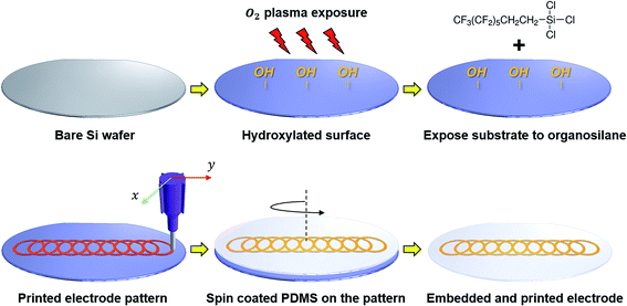
Aqueous 1 wt% of Ag NWs suspension was purchased from N&B Inc., Korea. Polydimethylsiloxane (PDMS) elastomer and a curing agent (Sylgard 184 A & B) were purchased from Dow Corning, Inc. To fabricate the strain sensor, we used a printing machine (Enjet Inc., Korea (http://www.enjet.co.kr)). The printer can move the substrate stage in the X–Y axis and the nozzle in the Z-axis by using a computer software aided by controller. A micro-syringe pump was used to supply the Ag NWs suspensions from 1 ml of syringe into the metallic nozzle. The flow rate was kept at 2 μl min−1 to supply constant flow of the conductive ‘ink’. The nozzle was a 21G (I.D.: 0.51 mm, O.D.: 0.81 mm) stainless steel needle. The distance of the tip-to-the-substrate was set at around 50 μm to stabilize the DNP.As shown in Fig. 1, stretchable Ag NWs/PDMS composite strain sensor was fabricated as following several steps. First, an atmospheric RF plasma system (IHP-1000, APPlasma Co., Korea) was used to produce an hydroxylated surface on the pre-cleaned silicon wafer substrate with acetone, ethanol, and deionized (DI) water. In order to reduce the pattern width and to easily peel off PDMS, a trichloro (1H,1H,2H,2H-perfluorooctyl) silane (Sigma Aldrich, Inc.) was deposited on the hydroxylated substrate before printing using atmospheric chemical vapour deposition (CVD) for 2 hours at room temperature.12 Second, Ag NWs electrodes with a line width of up to 500 μm were patterned using a dispensing method on the hydrophobic self-assembled monolayer (SAM) surface with a printing speed of 1 to 9 mm s−1. Liquid PDMS (15 ml) was then fully mixed with a curing agent (1.5 ml) at a 10![[thin space (1/6-em)]](https://www.rsc.org/images/entities/char_2009.gif) :
:![[thin space (1/6-em)]](https://www.rsc.org/images/entities/char_2009.gif) 1 volumetric ratio using a THINKY mixing machine (ARE-310, Thinky Inc.). The Ag NWs pattern was then spin coated with the liquid PDMS mixture at 500 rpm for 1 minute to obtain an elastomer thickness of around 100 μm. When the liquid PDMS is cast onto the printed Ag NWs pattern, it penetrates into the pores of the Ag NWs network due to the low viscosity and low surface energy.10 Finally, after curing all the materials for 3 hours at 80 °C on a hot plate, the Ag NWs/PDMS composite strain sensor was manually peeled off from the substrate. For the measurement of electrical performances of the Ag NWs/PDMS strain sensor during stretching, eutectic gallium–indium (EGaIn) (Sigma Aldrich, Inc.) liquid metal was applied.
1 volumetric ratio using a THINKY mixing machine (ARE-310, Thinky Inc.). The Ag NWs pattern was then spin coated with the liquid PDMS mixture at 500 rpm for 1 minute to obtain an elastomer thickness of around 100 μm. When the liquid PDMS is cast onto the printed Ag NWs pattern, it penetrates into the pores of the Ag NWs network due to the low viscosity and low surface energy.10 Finally, after curing all the materials for 3 hours at 80 °C on a hot plate, the Ag NWs/PDMS composite strain sensor was manually peeled off from the substrate. For the measurement of electrical performances of the Ag NWs/PDMS strain sensor during stretching, eutectic gallium–indium (EGaIn) (Sigma Aldrich, Inc.) liquid metal was applied.
2.2. Characterization
The morphology and dimensions of the printed Ag NWs electrodes were obtained using an optical microscope (Nikon Eclipse LV100ND Stand) and field-emission scanning electron microscopy (FE-SEM) (JEOL, 7600F) operated at 15 kV. To prove the crystallinity and phase of the Ag NWs, we deposited Ag NWs on a substrate by a drop casting method and observed the powder X-ray diffraction (XRD) (Bruker Corporation, HP-Powder XRD) pattern and transmission electron microscope (TEM) (JEOL, JEM-3010) images of the samples (ESI, Fig. S1†). A stretching test of the strain sensors was carried out on a purpose-built testing machine. Mechanical simulation was conducted using static structure analysis within commercially available software (ANSYS workbench 14.0). To attach our printed sensor to the curvilinear body, we connected copper film to each side of the sensor. We then measured the relative change value of resistance with time using a source meter (Keithley 2400, Keithley Instruments Inc.).3. Results and discussion
3.1. Printed Ag NWs/PDMS composite strain sensor
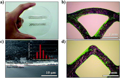
Fig. 2a shows a photo of the printed Ag NWs/PDMS composite strain sensor. The aqueous 1 wt% of Ag NWs suspension was printed through the metallic nozzle. According to the previous research reports related to the Ag NWs electrodes, screen printing method has commonly been used for patterning the conductor.9,10,13 However, the screen printing method must be performed with a pre-patterned mask to support the ink-blocking stencil to receive a desired pattern. In terms of the material consumption and the arbitrary patterning availability, it is not a practical method and makes it difficult to enhance efficient productivity of the target applications. In addition, one of the most critical limitations of masking is that it cannot draw the woven mesh structures (e.g., transparent metal-grid pattern).14 As shown in Fig. 2b and d, the mesh-grid pattern of Ag NWs could be successfully drawn with different shapes, which are defined by overlapped rings and diamonds. Owing to the hydrophobic organosilane treated surface, a patterned Ag NWs network could be fully embedded onto the PDMS layer, as presented in the SEM image of Fig. 2c. Also, according to our previous report, the low surface energy of the substrate can reduce the line width.15 The mean width and length of the employed Ag NWs in this study are 40 ± 7 nm and 20 ± 5 μm, respectively, as shown in the inset of Fig. 2c.To vary electrical resistance, the printing speed should be properly adjusted. Fig. 3a shows that the line width of the pattern was dependent on the printing speed from 1 mm s−1 to 9 mm s−1 at the constant experimental conditions (e.g., flow rate (2 μm min−1) and an inner diameter of nozzle (∼510 μm), etc.). Intuitively, a narrow line width contains lower concentrated Ag NWs, which in turn leads to a higher electrical resistance value from 2.93 ± 0.11 Ω to 13.6 ± 0.25 Ω. As shown in Fig. 3b, during printing, we expected that the printing speed can tune the electrical resistance to match individual applications, such as a high sensitivity coupled with relatively low volume fraction of Ag NWs and vice versa. Moreover, both the size of the diameter of the nozzles and the flow rate are important factors when functional inks are ejected from the nozzle. While the conventional screen printing method should be routinely performed to enhance electrical performances with wasting materials, DNP could control the volume of materials effectively without limitations.
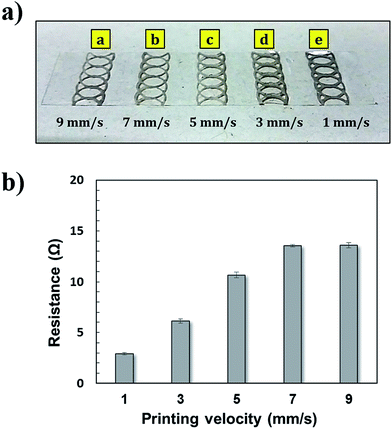 | ||
| Fig. 3 (a) A snapshot of printed Ag NWs/PDMS strain sensors at varying printing speeds from 1 to 9 mm s−1; (b) electrical resistance value (Ω) of each pattern. | ||
3.2. Static simulation of electrode according to geometry
In order to investigate the mechanical reliability of the Ag NWs/PDMS composite conductor, we carried out static structure simulation to calculate the magnitude of strain at the cross-linked points (i.e., nodes) after stretching. In all cases, the conductor used for static analysis is a composite with a line width of 0.5 mm. Prediction of the elastic modulus of the Ag NWs/PDMS composite could be simply calculated using the Halpin–Tsai equation,16where lf and df are the length and the diameter of the Ag NWs, respectively, and η can be derived by
where Ef is the elastic modulus of bulk silver (Ag). As explained in Section 3.1, we could easily control the volume fraction of the conductive NWs within elastomers using various printing conditions. In the case of 9 mm s−1 speed printing, the volume fraction of Ag NWs was around 2–3%. From the calculations, the elastic modulus of our Ag NWs/PDMS composite was around 10–20 MPa.
The dimensions of the ring and diamond model are defined as shown in Fig. 4; the inner radius (distance) value was 3 mm and the width value was 0.5 mm. According to Amir Jahanshahi et al.’s report, the amount of plastic strain on the structures, which were defined as a zigzag and horseshoe design, significantly differ17 from the perspective of the mechanical stability of electrodes, it is important to minimize the concentrated stress and strain at the interconnection during or after stretching to avoid failure of the conductor. It was concluded that the meander shape with rounded edges is the best condition because it has the smallest amount of local plastic strain.17 Based on these concepts, we carried out static simulation and evaluated four cases according to both the shape of the electrode and the number of nodes with the calculated elastic modulus.
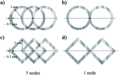 | ||
| Fig. 4 Configuration of the ring and diamond shape electrode according to cross-sectional points (red-colour nodes). | ||
Fig. 5 shows ring and diamond chain shapes of elastic strain electrodes. The stress concentration of the diamond shape was significantly focused on the angulate edges, while that of the ring shape was evenly distributed along the rounded edges. In addition, the number of nodes was another factor that enhanced stability. The elastic strain of the conductor with only 1 node was considerably larger than that of the conductor with 5 nodes. This means that the position or alignment change of Ag NWs inside the PDMS elastomer will significantly affect the resistance change, and also the sensitivity of the strain gauge can be increased (ESI, Fig. S2†).
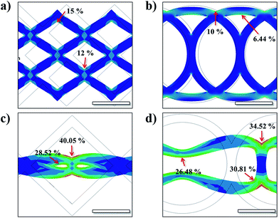 | ||
| Fig. 5 Total equivalent elastic strain of each electrode. The amount of plastic strain is shown on the structures. | ||
3.3. Electrical performances of strain sensor
Fig. 6 shows the relative resistance change (ΔR/R0) as a function of the applied tensile strain during the stretching and releasing processes. The resistive type strain sensor usually suffers from large hysteresis and non-linearity under large strain.9,10 However, we demonstrated that the hysteresis performance of our strain sensor could be almost recovered according to the geometry of the printed electrodes at up to 60% strain. During the stretching and releasing cycles, the diamond shape strain sensor has large hysteresis, as was simply predicted through the static simulation results. On the other hand, the sensor based on the ring shaped electrode endures continuous cycles. This means that the experimental results were well matched with the prediction based on static simulation. Therefore, the strain sensor composed of the ring shaped electrode is more suitable to apply to real devices.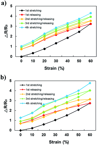 | ||
| Fig. 6 Strain sensing capability of the printed resistive type sensor composed of (a) ring and (b) diamond shaped electrodes. | ||
3.4. Response of our strain sensor
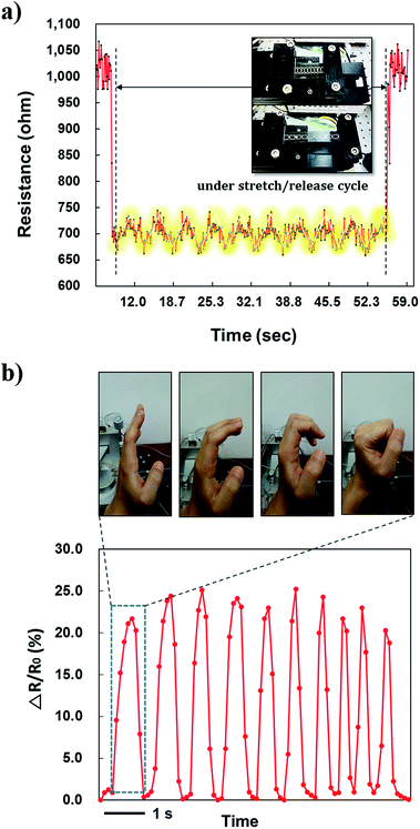
We tested the strain sensing response by using our home-built stretching tester as shown in Fig. 7a. The relative resistance change was measured according to the movement generated by linear motors. As a result, we got the repeatable saw-tooth shaped peaks when the strain sensor was stretched for a minute. The sensor response was acceptable under hand-testing model because the intensity of the signal peaks corresponded to the motion. However, after over the 50 stretching cycles, the resistance was gradually increased because of the deformation of the nanocomposite. This limitation should be overcome and we will further study to improve the stability. In addition, to examine human body motion with the DNP strain sensor, we measured the time response of our sensor after we attached it to a finger. After mounting the sensor on the finger, the experimenter squeezed and opened his hand repeatedly as shown in Fig. 7b. The one cycle of gestures (i.e., squeeze/open) took a short time, around 1 second. When a squeezing motion of the finger was used, the relative change value of resistance was slightly increased, whereas the effect of the opening hand on strain decreased, and the change value of resistance was restored to the original value. For the future device, a multiple array of strain sensors could be attached to all the fingers using our direct printing method.4. Conclusions
In this study, we fabricated a stretchable Ag NWs/PDMS composite strain gauge with arbitrary micro-pattern (i.e. ring and diamond shapes) electrodes in order to optimize stretchability. The mesh-grid Ag NWs pattern could be successfully drawn by dispensing nozzle printing (DNP). We embedded the NWs into the PDMS elastomer after patterning. In addition, the electrical resistance could be modified according to the specific printing condition such as the speed of the nozzle. We carried out static simulation on the two geometries to compare the patterns when the strain sensor is stretched. As a result, we obtained a highly stretchable strain sensor with suitable electrode design, which can be obtained using DNP. Based on the results, the authors assume that directly drawn electronic skin (E-skin) can be applied for multifunctional sensors in the near future.Acknowledgements
This research was supported by the Basic Science Research Program through the National Research Foundation of Korea (NRF) (Grant number: 2014-023284) and the Global Ph.D. Fellowship Program through the National Research Foundation of Korea (NRF) (Grant number: NRF-2013H1A2A1032532).References
- A. Kamyshny and S. Magdassi, Small, 2014, 10, 3515–3535 CrossRef CAS.
- H. Lee, B. Seong, J. Kim, Y. Jang and D. Byun, Small, 2014, 10, 3918–3922 CrossRef CAS PubMed.
- Y. J. Jeong, H. Lee, B. S. Lee, S. Park, H. T. Yudistira, C. L. Choong, J. J. Park, C. E. Park and D. Byun, ACS Appl. Mater. Interfaces, 2014, 6, 10736–10743 CAS.
- J. T. Muth, D. M. Vogt, R. L. Truby, Y. Mengüç, D. B. Kolesky, R. J. Wood and J. A. Lewis, Adv. Mater., 2014, 26, 6307–6312 CrossRef CAS PubMed.
- B. Y. Ahn, E. B. Duoss, M. J. Motala, X. Y. Guo, S. I. Park, Y. J. Xiong, J. Yoon, R. G. Nuzzo, J. A. Rogers and J. A. Lewis, Science, 2009, 323, 1590–1593 CrossRef CAS PubMed.
- S. K. Lee, B. J. Kim, H. Jang, S. C. Yoon, C. Lee, B. H. Hong, J. A. Rogers, J. H. Cho and J. H. Ahn, Nano Lett., 2011, 11, 4642–4646 CrossRef CAS PubMed.
- S. H. Jeong, A. Hagman, K. Hjort, M. Jobs, J. Sundqvist and Z. G. Wu, Lab Chip, 2012, 12, 4657–4664 RSC.
- M. Park, J. Park and U. Jeong, Nano Today, 2014, 9, 244–260 CrossRef CAS PubMed.
- S. S. Yao and Y. Zhu, Nanoscale, 2014, 6, 2345–2352 RSC.
- M. Amjadi, A. Pichitpajongkit, S. Lee, S. Ryu and I. Park, ACS Nano, 2014, 8, 5154–5163 CrossRef CAS PubMed.
- Y. X. Jin, D. Y. Deng, Y. R. Cheng, L. Q. Kong and F. Xiao, Nanoscale, 2014, 6, 4812–4818 RSC.
- J. Kim, J. H. Ko, J. Lee, M. J. Kim and D. Byun, Appl. Phys. Lett., 2014, 104, 223702 CrossRef PubMed.
- F. Xu and Y. Zhu, Adv. Mater., 2012, 24, 5117–5122 CrossRef CAS PubMed.
- Y. Jang, J. Kim and D. Byun, J. Phys. D: Appl. Phys., 2013, 46, 155103 CrossRef.
- Y. Jang, I. H. Tambunan, H. Tak, V. D. Nguyen, T. Kang and D. Byun, Appl. Phys. Lett., 2013, 102, 123901 CrossRef PubMed.
- H. Denver, T. Heiman, E. Martin, A. Gupta and D. A. Borca-Tasciuc, J. Appl. Phys., 2009, 106, 064909 CrossRef PubMed.
- A. Jahanshahi, M. Gonzalez, J. van den Brand, F. Bossuyt, T. Vervust, R. Verplancke, J. Vanfleteren and J. De Baets, Jpn. J. Appl. Phys., 2013, 52, 05DA18 CrossRef.
Footnote |
| † Electronic supplementary information (ESI) available. See DOI: 10.1039/c5ra01519g |
| This journal is © The Royal Society of Chemistry 2015 |

