In situ synthesis of gold nanoparticles on LBL coated nanofibers by tannic acid for catalytic application

Bin Zhouab, Xing Jinc, Hongshan Liangab, Jing Liab, Shilin Liuab, Yan Liab, Yijie Chenab and Bin Li*ab
aCollege of Food Science and Technology, Huazhong Agriculture University, Wuhan 430070, China. E-mail: libinfood@mail.hzau.edu.cn; Fax: +86 27 8728 8636; Tel: +86 27 6373 0040
bKey Laboratory of Environment Correlative Dietology (Huazhong Agricultural University), Ministry of Education, China
cDepartment of Clinical Laboratory, Xi'an Gaoxin Hospital, Xi'an 710075, China

Received 25th January 2015 , Accepted 10th March 2015

First published on 10th March 2015


Abstract

Electrospinning nanofibrous mats are extensively studied as efficient two-dimensional nanomaterials and applied in the fields of filtration, catalysis, and biosensors due to their flexibility and porosity. In this article, gold nanoparticle (AuNPs) loaded composite nanofibers were fabricated by a simple method, which consisted of the preparation of the nanofibers by electrospinning, the deposition of tannic acid (TA) on the surface of the nanofibers via layer-by-layer assembly and the reduction of the AuNPs on the nanofibrous mats. The as-prepared nanofibers were characterized by scanning electron microscopy (SEM), energy dispersive spectroscopy (EDS), transmission electron microscopy (TEM), Fourier transform infrared spectroscopy (FTIR), X-ray diffraction (XRD), and X-ray photoelectron spectroscopy (XPS), respectively. The results revealed that AuNPs were successfully generated on the nanofibers without aggregation. In addition, by adjusting the number of the bilayers in the assembly process, the content of gold supported on the nanofibrous mats could be easily controlled. The catalytic performance of the hybrid nanofibrous mats on the reduction of 4-nitrophenol (4-NP) with sodium borohydride was monitored by UV-visible spectroscopy (UV-vis). Notably, the hybrid composite nanofibrous mats could be easily separated from the reaction mixture.
1. Introduction

During the past decade, noble metallic nanoparticles, such as Au, Ag, Pt, have received considerable interest due to their unique physical and chemical properties and their potential utility in catalysis, such as in the reduction of 4-nitrophenol (4-NP) to 4-aminophenol (4-AP),1,2 CO oxidation,3 propylene epoxidation,4 and the oxidation of alcohols.5,6

As is well-known, 4-NP is a common organic pollutant in industrial and agricultural waste water.7 In recent years, the reduction of 4-NP in the presence of sodium borohydride (NaBH4) has been extensively studied for the efficient and eco-friendly production of 4-AP, which is a vital intermediate for the manufacture of analgesic, antipyretic drugs, corrosion inhibitors.8,9 To make the route possible, various noble metals, including Au, Ag, Pt nanocrystals and alloys have been widely used due to their outstanding catalytic activities.8,10,11

However, smaller unsupported nanoparticles tend to easily aggregate owing to their large surface area-to-volume ratio and are difficult to remove from the reaction media.8 Thus, we ought to discover an alternative method or material which remains merits and overcomes disadvantages of the materials. To overcome these limitations, the immobilization of nanoparticles on suitable substrate was an alternative way.

Recently, the impact of membrane technology has exponentially increased in research settings and industrial applications.12 Two dimensional membrane materials that are constructed by micro- or nano-fibers are intensively applied as substrate materials in the fabrication of functional nanomaterials due to their flexibilities, high specific surface area and porosity.13

Electrospinning is an attractive way for manufacturing nanofibers with controllable compositions and structures.14 It is an efficient and straightforward method of producing ultrafine fibers with micro- to nano-scale and with controlled surface morphology. Electrospun nanofibrous membranes possess several attractive features, such as large surface-to-volume ratio, high porosity, and interconnected open pore structure,15 which make them very attractive in separation technology and catalysis, et al.

The combination of nanoparticles into electrospun nanofibers has been performed predominately using two different ways. One method is the in situ generation of particles in the fiber support by co-electrospinning a mixed solution of polymer and desired metal salt. Subsequent heating of the membrane yields fibers decorated with metal nanoparticles in both the interior and exterior of the fiber. An alternative is the post-treatment of the membrane in order to deposit metal nanoparticles strictly on the surface of the fibers.

In this current work, freshly prepared electrospun cellulose nanofibrous membranes were first coated with lysozyme (Lys) and tannic acid (TA) via layer-by-layer assembly technique. Then, AuNPs were in situ reduced by TA and immobilized into the Lys/TA shell. Scanning electron microscopy (SEM), Fourier transform infrared (FTIR) spectroscopy, transmission electron microscopy (TEM), energy dispersive spectroscopy (EDS), X-ray diffraction (XRD), and X-ray photoelectron spectroscopy (XPS) were utilized to characterize the morphology and composition of AuNPs-containing nanofibrous membranes. Finally, the catalytic properties of AuNPs-immobilized composite nanofibers were investigated using 4-NP as a model substrate. The results revealed that the composite nanofibrous membranes displayed fine catalytic efficiency to reduce 4-NP to 4-AP.

2. Materials and methods

Materials

Cellulose acetate (CA, Mn 30[thin space (1/6-em)]000) was purchased from Sigma-Aldrich Co., USA. Hen egg white lysozyme, HAuCl4·3H2O, sodium borohydride (NaBH4) and 4-nitrophenol (4-NP) were obtained from the Sinopharm Chemical Reagents Co., Ltd. (Shanghai, China). Tannic acid was purchased from Aladdin Chemistry Co. Ltd. (Shanghai, China). The other reagents were analytical grade purchased from China National Pharmaceutical Group Industry Corporation Ltd. All aqueous solutions were prepared using purified water with a resistance of 18.2 MΩ cm.

Fabrication of template nanofibers

CA nanofibers were fabricated by using modified Ding's method.16,17 17% CA solution was prepared by dissolving CA powder in a mixed solvent (acetone/DMAc = 2[thin space (1/6-em)]:[thin space (1/6-em)]1 w/w). The homemade equipment consisted of a syringe pump (LSP02-1B, Baoding Longer Precision Pump Co., Ltd., China) and a high voltage power supply (DW-P303-1ACD8, Tianjin Dongwen Co., China). A grounded cylindrical layer was used as a collector which rotated with a rotational velocity of 50 rpm. The applied voltage was 17 kV and the tip-to-collector distance was 20 cm. The ambient temperature and relative humidity was maintained at 25 °C and 45%, respectively. The prepared mats were dried at 40 °C in vacuum for 24 h to remove the trace solvent. The CA mats were hydrolyzed in NaOH solution (0.05 M) at room temperature for 7 days following the previous reports.18,19

Construction of nanocomposite membranes on cellulose nanofibers

The bilayer film was then deposited, by spraying Lys (1 mg mL−1 lysozyme, pH 7.4, in 0.01 M PBS) followed by tannic acid (1 mg mL−1, pH 7.4, in 0.01 M PBS) each for 10 mL solution. After each deposition step, a 5 second wash with 0.01 M PBS (pH 7.4) was sprayed.20,21 Here, (Lys/TA)n was used as a formula to label the LBL structured films, where n was the number of the Lys/TA bilayers. The LBL films coated fibrous mats were dried at 40 °C for 2 h under vacuum prior to further characterizations.

Characterization of composite nanofibrous membranes

The surface morphologies and chemical compositions of the composite nanofibrous mats were measured by scanning electron microscopy (SEM) and energy dispersive spectroscopy (EDS) with a JEOL JSM-6390LV SEM equipped with an Oxford INCA EDS detector. Fourier transform infrared (FT-IR) spectra were acquired on a Nicolet170-SX instrument (Thermo Nicolet Ltd., USA) in the wavenumber range of 4000–400 cm−1. The cross-sections of the nanofibers were observed using a JEOL transmission electron microscope (H-7650, Hitachi, Japan). X-ray photoelectron spectroscopy (XPS) was conducted on an axis ultra DLD apparatus (Kratos, U.K.). X-ray diffraction (XRD) was carried out using a diffract meter type D/max-rA (Rigaku Co., Japan) with Cu target and Ka radiation (λ = 0.154 nm).

Fabrication of AuNPs@Lys/TA composite membranes

The as-prepared Lys/TA composite membranes were immersed into chloroauric acid solution with different concentrations (1 mM and 5 mM) until the color of the membranes changed into dark violet. Then, they were washed thoroughly with ultrapure water to remove the AuCl. Finally, the AuNPs@Lys/TA composite membranes were dried at room temperature for 2 h under vacuum prior to further characterizations.

Catalytic reduction of 4-NP

To study the catalytic activity, 3 mg AuNPs@Lys/TA composite nanofibers were added into 4 mL of 4-NP aqueous solution (0.12 mM). Subsequently, the above solution was mixed with 4 mL fresh NaBH4 solution (5 mM). The reaction was carried out at 298 K with continuous stirring. Parts of the mixture were filtered through a 0.22 μm membrane filter after every 2 min for the determination with UV-vis absorption spectra.22

3. Results and discussion

Surface morphology analysis of Lys/TA nanofibrous membranes

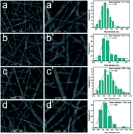
To investigate the impact of Lys and TA deposition on the morphology of the cellulose nanofibrous membranes, the surface morphology analysis of the composite fibrous mats were conducted by SEM. The representative SEM images of cellulose nanofibrous mats showed in Fig. 1 revealed randomly oriented 3D nonwoven mats with an average diameter of 477.3 nm. They possessed loosely packed cylindrical fibers and were continuous and long without any defects (Fig. 1a and a′). To study the impact of assembly process and the number of coating bilayers on the formation of composite films, the cellulose fibers were coated with various bilayers of Lys and TA.
image file: c5ra01483b-f1.tif
Fig. 1 SEM images of (a–d): cellulose nanofibrous mats, (Lys/TA)2, (Lys/TA)5, and (Lys/TA)10. Image (a′–d′) showed high magnification images of (a–d), respectively. The right column reveals the diameter distribution histograms of the nanofibrous mats.

From the SEM images, we can see that not only the diameter but also the morphology of all samples changed obviously attributed to the deposited of Lys and TA on the surface of nanofibers. After the LBL films were coated, the nanofibers showed a higher surface roughness on each fiber compared with the smooth surface of the cellulose nanofibers (Fig. 2a–d and a′–d′). As revealed in Fig. 1b′–d′, we can see that, after the assembly process, a Lys/TA shell layer were visible around the cellulose nanofibers. Also, the thickness of the shell layer increased with the increase of the bilayer number, which led to the increase of the fibers diameter (shown in the right column of Fig. 1). Mentionablely, vacuum-assisted method was used in order to keep the incompact stacking style of the fibers. These images visually demonstrated that Lys and TA were successfully assembled onto the surface of the cellulose fibers.


image file: c5ra01483b-f2.tif
Fig. 2 FT-IR spectra of (a–e): Lys, TA, (Lys/TA)5, (Lys/TA)10, and cellulose nanofibrous mats.

FT-IR spectra of Lys/TA nanofibrous mats

Fig. 2 displayed the FTIR spectra of the raw materials and the composite nanofibrous membranes. All membranes showed a abroad absorption band at about 3500–3100 cm−1, which denoted the free O–H stretching vibration of hydroxyl groups.23 Moreover, cellulose nanofibrous mats also displayed absorption bands at 1637, 1066, 1238, 1164, 1052 and 897 cm−1, corresponding to –OH bending,24 C–O stretching, C–O–C asymmetric stretching and C1–H deformation vibrations, respectively25 (Fig. 2e). The spectrum of Lys, showed in Fig. 2a, contained two characteristic peaks. The amide I band (about 1654 cm−1) was relevant to the C[double bond, length as m-dash]O stretching mode, whereas the amide II band (about 1540 cm−1) was attributed to the stretching mode of N–H vibrations.26,27 For the LBL coated films, the observed increase in intensity of the absorption band at 1716 and 1615 cm−1 as shoulders of the amide I or –OH bending was due to the carbonyl CO vibration of the TA ester bond and C[double bond, length as m-dash]C stretching vibrations of aromatic ring, respectively.17 In addition, compared with the spectrum of cellulose nanofibers, the presence of the peak located at 1540 cm−1 and accompanied with a shoulder peak was attributed to the N–H vibrations and C[double bond, length as m-dash]C stretching vibrations, respectively (Fig. 2a–d). For the composite membranes, the enhancement of the band at 1323 cm−1 and 1204 cm−1 was caused by the C–O stretch of the acid group in TA and C–O stretch in polyols, respectively.28 The band at 759 cm−1 could be related to the C–H out plane bend of phenyl group.29 On the base of the above results, we could see that Lys and TA were deposited on the surface of the cellulose fibers.

Surface and cross-sectional morphology analysis of AuNPs@Lys/TA nanofibrous membranes

The AuNPs were synthetized in the shell of the Lys/TA nanofibers via in situ reduction. In order to comfirm the generation of AuNPs, the surface and cross-sectional morphology analysis of AuNPs-immobilized Lys/TA nanofibrous membranes was performed by SEM and TEM, respectively. The SEM images of (AuNPs@Lys/TA)10 were displayed in Fig. 3. Round-shaped AuNPs with a relatively uniform distribution were clearly observed, illustrating that AuNPs were successfully generated along the cross section of the fibers. It can be seen that an obvious morphological transformation of the Lys/TA nanofibers surface from relatively smooth to coarse appeared after LBL assembly process.
image file: c5ra01483b-f3.tif
Fig. 3 SEM images of (AuNPs@Lys/TA)10 (a); high magnification image (b).

We also investigated the morphology and size distribution of AuNPs in the Lys/TA shell. Fig. 4 displayed the cross-sectional TEM images of AuNP-containing Lys/TA composite nanofibers and the size distribution histogram of the AuNPs formed in the shell. Clearly, AuNPs were homogeneously distributed within the Lys/TA shell, forming a nanometer-scale thick composite coating around the cellulose fiber core. It can be seen that almost all of the AuNPs were embedded in the Lys/TA matrix. The average diameter of the AuNPs was about 20.78 nm obtained by Nano Measurer 1.2. Mentionablely, we found that the size of AuNPs on the outmost layer was larger than the inners' mainly caused by higher AuCl concentration at the interface. The AuNPs revealed a larger particle size of 39.52 nm, when synthetized in AuCl solution (5 mM) (Fig. S1).


image file: c5ra01483b-f4.tif
Fig. 4 Cross-sectional TEM images of AuNPs-immobilized nanofibers with different magnification (reduced in 1 mM HAuCl4 solution) (a–c); the particle size distribution histogram (d).

Surface composition measurement of the composite nanofibrous membranes

More detailed information regarding the chemical and bonding environment of the composite nanofibrous membrane ((AuNP@Lys/TA)10) was ascertained using XPS and EDS. Fig. 5a showed the survey scanned spectra in the range of 0–1000 eV. The overview spectra revealed that C 1s, O 1s, N 1s, S 2p, and Au 4f existed in (AuNP@Lys/TA)10, however, only C and O elements existed in bare cellulose nanofibers.30 The C 1s core-level photoelectron spectrum (Fig. 5b) could be curved into three peak components located at about 284.6 eV, 286.4 eV, and 287.9 eV, which were attributed to C–C, C–O, and C[double bond, length as m-dash]O or O–C[double bond, length as m-dash]O group from TA or Lys.17,31 Moreover, the presence of peaks posited at about 400 eV and 164 eV confirmed the successfully assembly of Lys and TA on the surface of the nanofibers. In addition, the Au 4f core-levels shows two peaks at 84.71 eV and 88.39 eV, which were assigned to 4f7/2 and 4f5/2, respectively (Fig. 5e). The position and θ difference between the two peaks (3.7 eV) well matched with the value reported for Au0, suggesting the existence of Au NPs.32
image file: c5ra01483b-f5.tif
Fig. 5 XPS survey spectra of (AuNPs@Lys/TA)10 (a) and core-level spectra of C 1s, N 1s, S 2p, and Au 3d (b–e); EDS spectra of (AuNPs@Lys/TA)10 (f).

To further confirm the surface chemical information of the nanocomposite, EDS analysis was also conducted (Fig. 5f). The result disclosed the elemental compositions of the nanofibrous membranes and the observed C, O, N, S, and Au elements which ensured the involvement of Lys and TA in them. The EDS result also confirmed the AuNPs were successfully synthetized and immobilized into the nanofibers, which was consistent with the XPS results.

Crystalline property of AuNPs@Lys/TA nanofibrous mats

To further verify the formation of the AuNPs on the coating shell, structural characterizations were conducted by XRD analysis. As shown in Fig. 6, XRD patterns of the different samples were revealed. From Fig. 6a we could see that cellulose nanofibers exhibited a typical cellulose II crystal with three characteristic diffraction peaks at 12.2, 20.1, and 21.8°.33 The XRD pattern of the AuNPs-loading nanocomposite membranes also contained the characteristic diffraction peaks of cellulose, along with 38.31°, 44.58°, 64.78°, and 77.79° peaks, could be attributed to the reflections, which well matched with the standard JCPDS data (040784) of fcc Au corresponding to the (111), (200), (220), and (211) lattice planes.34,35 It could be seen that with the increase of layer number, the diffraction peak intensity increased significantly, which caused by higher amount of the AuNPs.
image file: c5ra01483b-f6.tif
Fig. 6 XRD patterns of cellulose nanofibrous mats (a), (AuNPs@Lys/TA)5 (b), (AuNPs@Lys/TA)10 (c).

Catalytic reduction of 4-NP

We also investigated the possible application of the AuNPs-immobilized Lys/TA composite nanofibers in reduction of nitroaromatic. The catalytic reduction of 4-NP to 4-AP with an excess amount of NaBH4 become one of the model reaction to evaluate the catalytic performance of novel nanoparticles.5 The colour of reaction mixture changed from light yellow to dark yellow owing to the generation of 4-nitrophenolate ion with the addition of the NaBH4.36 As shown in Fig. 7a, there was little effect on the decrease in absorbance at 400 nm within 24 min, indicating that neither cellulose nanofiber nor Lys/TA shell had any catalytic activity for the reduction of 4-NP. Theoretically, the reaction was a thermodynamically feasible process, but it was kinetically restricted in the absence of a catalyst.22 However, with the addition and proper mixing of AuNPs@Lys/TA composite nanofibers, the reaction could conduct, where the kinetics could be easily monitored spectrophotometrically associated with the observation of a fading and ultimate bleaching of the yellow color of reaction mixture.
image file: c5ra01483b-f7.tif
Fig. 7 Catalytic performance of composite nanofibrous mats. (a) At/A0 versus reaction time for the reduction of 4-NP; (b) catalytic activity of the (AuNPs@Lys/TA)5 with three times of cycling uses.

The catalytic efficiency was enhanced with the increasing of the content of gold on the nanofibrous mats by increase the number of the bilayer. Furthermore, Fig. 7b showed the catalytic reaction of 4-NP over (AuNPs@Lys/TA)5 with high catalytic activity could be conveniently separated from the reaction mixture, and would greatly promote their industrial application.

4. Conclusions

In summary, we have successfully developed a facile and green approach to synthesize and immobilize AuNPs onto cellulose nanofibers. The immobilization of the AuNPs with an average diameter of 20.78 nm within the Lys/TA shell did not impact the porous fibrous structure of the mats. The composite nanofibrous mats were characterized by SEM, TEM, XRD, XPS, and so on. Finally, the catalytic efficiency was enhanced with the increasing of the number of bilayer caused by the increase of the AuNPs amount in the Lys/TA shell. Notably, the AuNPs@Lys/TA composite nanofibers could be easily separated from the reaction mixture.

Acknowledgements

The present work is supported financially by the National Natural Science Foundation of China (Grant no. 31371841). The authors greatly thank colleagues of Key Laboratory of Environment Correlative Dietology of Huazhong Agricultural University for offering many conveniences.

References

  1. B. Baruah, G. J. Gabriel, M. J. Akbashev and M. E. Booher, Langmuir, 2013, 29, 4225–4234 CrossRef CAS PubMed.
  2. R. Ciganda, N. Li, C. Deraedt, S. Gatard, P. Zhao, L. Salmon, R. Hernandez, J. Ruiz and D. Astruc, Chem. Commun., 2014, 50, 10126–10129 RSC.
  3. A. A. Herzing, C. J. Kiely, A. F. Carley, P. Landon and G. J. Hutchings, Science, 2008, 321, 1331–1335 CrossRef CAS PubMed.
  4. Y. Lei, F. Mehmood, S. Lee, J. Greeley, B. Lee, S. Seifert, R. E. Winans, J. W. Elam, R. J. Meyer, P. C. Redfern, D. Teschner, R. Schlögl, M. J. Pellin, L. A. Curtiss and S. Vajda, Science, 2010, 328, 224–228 CrossRef CAS.
  5. J. Li, C.-Y. Liu and Y. Liu, J. Mater. Chem., 2012, 22, 8426 RSC.
  6. A. S. K. Hashmi and G. J. Hutchings, Angew. Chem., Int. Ed., 2006, 45, 7896–7936 CrossRef PubMed.
  7. J.-R. Chiou, B.-H. Lai, K.-C. Hsu and D.-H. Chen, J. Hazard. Mater., 2013, 248–249, 394–400 CrossRef CAS PubMed.
  8. S. Zhang, S. Gai, F. He, S. Ding, L. Li and P. Yang, Nanoscale, 2014, 6, 11181–11188 RSC.
  9. Z. Zhang, C. Shao, P. Zou, P. Zhang, M. Zhang, J. Mu, Z. Guo, X. Li, C. Wang and Y. Liu, Chem. Commun., 2011, 47, 3906–3908 RSC.
  10. S. Tang, S. Vongehr and X. Meng, J. Mater. Chem., 2010, 20, 5436–5445 RSC.
  11. S. Zhou, K. McIlwrath, G. Jackson and B. Eichhorn, J. Am. Chem. Soc., 2006, 128, 1780–1781 CrossRef CAS PubMed.
  12. E. Formo, M. S. Yavuz, E. P. Lee, L. Lane and Y. Xia, J. Mater. Chem., 2009, 19, 3878 RSC.
  13. J. Wang, H. B. Yao, D. He, C. L. Zhang and S. H. Yu, ACS Appl. Mater. Interfaces, 2012, 4, 1963–1971 CAS.
  14. X. Wang, B. Ding, G. Sun, M. Wang and J. Yu, Prog. Mater. Sci., 2013, 58, 1173–1243 CrossRef CAS PubMed.
  15. N. Wang, X. Wang, B. Ding, J. Yu and G. Sun, J. Mater. Chem., 2012, 22, 1445–1452 RSC.
  16. X. Mao, B. Ding, M. Wang and Y. Yin, Carbohydr. Polym., 2010, 80, 839–844 CrossRef PubMed.
  17. B. Zhou, J. Xing, J. Li, W. Xu, Y. Li and B. Li, RSC Adv., 2014, 4, 54517–54524 RSC.
  18. J. Du, X. Li, C. Yang, W. Li, W. Huang, R. Huang, X. Zhou and H. Deng, Curr. Nanosci., 2013, 9, 8–13 CAS.
  19. H. B. Deng, X. Zhou, X. Y. Wang, C. Y. Zhang, B. Ding, Q. H. Zhang and Y. M. Du, Carbohydr. Polym., 2010, 80, 474–479 CrossRef CAS PubMed.
  20. A. Shukla, J. C. Fang, S. Puranam, F. R. Jensen and P. T. Hammond, Adv. Mater., 2012, 24, 492–496 CrossRef CAS PubMed.
  21. J. C. Antunes, C. L. Pereira, M. Molinos, F. Ferreira-da-Silva, M. Dessi, A. Gloria, L. Ambrosio, R. M. Goncalves and M. A. Barbosa, Biomacromolecules, 2011, 12, 4183–4195 CrossRef CAS PubMed.
  22. P. Zhang, C. Shao, Z. Zhang, M. Zhang, J. Mu, Z. Guo and Y. Liu, Nanoscale, 2011, 3, 3357–3363 RSC.
  23. X. Cao, B. Ding, J. Yu and S. S. Al-Deyab, Carbohydr. Polym., 2012, 90, 1075–1080 CrossRef CAS PubMed.
  24. J. Zhao, Z. Wei, X. Feng, M. Miao, L. Sun, S. Cao, L. Shi and J. Fang, ACS Appl. Mater. Interfaces, 2014, 6, 14945–14951 CAS.
  25. B. Zhou, Y. Hu, J. Li and B. Li, Int. J. Biol. Macromol., 2014, 64, 402–408 CrossRef CAS PubMed.
  26. T. Zhang, P. Zhou, Y. Zhan, X. Shi, J. Lin, Y. Du, X. Li and H. Deng, Carbohydr. Polym., 2015, 117, 687–693 CrossRef CAS PubMed.
  27. Y. Zhan, W. Zeng, G. Jiang, Q. Wang, X. Shi, Z. Zhou, H. Deng and Y. Du, J. Appl. Polym. Sci., 2015, 132 Search PubMed.
  28. D. S. Sheny, J. Mathew and D. Philip, Spectrochim. Acta, Part A, 2011, 79, 254–262 CrossRef CAS PubMed.
  29. M. Meena Kumari, S. A. Aromal and D. Philip, Spectrochim. Acta, Part A, 2013, 103, 130–133 CrossRef CAS PubMed.
  30. W. Li, X. Y. Li, W. Li, T. Wang, X. X. Li, S. Y. Pan and H. B. Deng, Eur. Polym. J., 2012, 48, 1846–1853 CrossRef CAS PubMed.
  31. T. Zeng, X. Zhang, Y. Guo, H. Niu and Y. Cai, J. Mater. Chem. A, 2014, 2, 14807 CAS.
  32. N. Vasimalai and S. A. John, J. Mater. Chem. A, 2013, 1, 4475 CAS.
  33. B. Zhou, Y. Li, H. Deng, Y. Hu and B. Li, Colloids Surf., B, 2014, 116C, 432–438 CrossRef PubMed.
  34. S. K. Maji, S. Sreejith, A. K. Mandal, X. Ma and Y. Zhao, ACS Appl. Mater. Interfaces, 2014, 6, 13648–13656 CAS.
  35. J. Zheng, Y. Dong, W. Wang, Y. Ma, J. Hu, X. Chen and X. Chen, Nanoscale, 2013, 5, 4894–4901 RSC.
  36. L. Qiu, Y. Peng, B. Liu, B. Lin, Y. Peng, M. J. Malik and F. Yan, Appl. Catal., A, 2012, 413–414, 230–237 CrossRef CAS PubMed.

Footnote

Electronic supplementary information (ESI) available. See DOI: 10.1039/c5ra01483b

This journal is © The Royal Society of Chemistry 2015