Taejoo Lee†
,
Yunju Lee†,
Myung-Hyun Ryou* and
Yong Min Lee*
Department of Chemical and Biological Engineering, Hanbat National University, 125 Dongseodaero, Yuseong-gu, Daejeon 305-719, Republic of Korea. E-mail: yongmin.lee@hanbat.ac.kr; mhryou@hanbat.ac.kr; Fax: +82-42-821-1692; Tel: +82-42-821-1549 Tel: +82-42-821-1534
First published on 7th April 2015
A mussel-inspired polydopamine (PDA) coating turns radio-frequency (RF) Al2O3 sputtering – which thus far has not been appropriate for the surface treatment of porous polyolefin-based separators – into a damage-free, reliable, and cost-efficient process. Due to the thermally resistive PDA layers, polyethylene (PE) separators can sustain high-power Al2O3 sputtering conditions over 75 W, which significantly reduces processing time. Furthermore, compared to the as-prepared separators, PDA/Al2O3-coated PE separators also reveal improved thermal stability and cycle performance for lithium secondary batteries. PDA/Al2O3-coated PE separators retained their original size when exposed to temperatures of 145 °C over 30 min, while the bare PE separators shrank to 9% of their original size. At a temperature of 25 °C, the unit cell (LiMn2O4/separator/Li metal) employing the PDA/Al2O3-coated PE separators maintained 94.8% (103.4 mA h g−1) of the initial discharge capacity after 500 cycles at C/2 rate and 51.7% (56.7 mA h g−1) at 25 C rate, while the corresponding values for the bare PE separators were 89% (98.6 mA h g−1) at C/2 rate and 24.5% (27.2 mA h g−1) at 25 C rate.
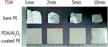
To the best of our knowledge, we were the first to report the feasibility of using radio-frequency (RF) magnetron sputtering to introduce binder-free inorganic coating layers (Al2O3 in the study) onto commercial PE separators.17 An optimal amount of hydrophilic Al2O3 coating layers creates desirable ionic pathways, resulting in enhanced rate capabilities of LIBs without blocking the pores, which are beneficial for holding larger amounts of liquid electrolyte. However, the sputtering time of longer than 10 minutes should be shortened to a few minutes for commercial application. Hence, in order to maintain the appropriate amount of sputtered coating materials, the RF power has to be increased, which might cause thermal damage to PE separators. A facile approach to circumvent this problem is to pre-coat the bare separator with polydopamine (PDA) for enhancing thermal stability, followed by high-power RF sputtering.
Thermal shrinkage ratio (%) = (Ai − Af)/Ai × 100 | (1) |
The electrolyte uptake amount was determined using eqn (2), where Wi and Wf indicate the separator weight before and after electrolyte absorption, respectively:
Uptake amount (wt%) = (Wf − Wi)/Wi × 100 | (2) |
The air permeability represented by the Gurley number was examined with a Gurley densometer (4110N, Thwing-Albert, USA) by measuring the time taken for air to pass through a determined volume under a given pressure. The Gurley number was determined according to procedure JIS-P8117 (Japanese Industrial Standards) by measuring the time (s) for 100 cm3 of air to pass through the membrane under a constant air pressure (6.52 psi).
The pulse-power of the unit cells was investigated using a hybrid pulse-power characterization (HPPC) test sequence.18–20 The test consisted of a 10 s discharge pulse (5 C, 4.3 mA cm−2), a 40 s rest, and a 10 s charge pulse (3.75 C, 3.225 mA cm−2) performed at every 10% state-of-charge (SOC) after precycling and high temperature storage. For the latter, the unit cells were stored at 60 °C for 3 days, followed by cooling down to 25 °C for 10 h.
To evaluate the rate capability, the unit half-cells (LiMn2O4/Li metal) were discharged with a varying discharge current density from 1 C to 30 C (1 C, 5 C, 10 C, 15 C, 20 C, 25 C, and 30 C), while maintaining the same charging current density of C/2 (0.44 mA cm−2). The unit cells were subsequently cycled at a C-rate of C/2 (0.44 mA cm−2) for 500 cycles to evaluate the cycle performance. For the evaluation of rate capability and cycle performance, CC/CV mode and CC mode were used during the charging process and discharging process, respectively, between 3.0 and 4.5 V vs. Li/Li+ at room temperature.
![]() | ||
Fig. 2 Scanning electron microscopy (SEM) images of (a and b) bare PE separators, (c and d) PDA-coated PE separators, and (e and f) PDA/Al2O3-coated PE separators. |
The physical properties of the separators, including thickness, Gurley number, liquid uptake amount, and ionic conductivity, were investigated and the results are listed in Table 1. As discussed above, the nano-scale coating layer thickness did not influence the total thickness of the separators. On the other hand, the Gurley number, a good indicator of the permeability of a membrane, increased from 271 to 295 and 299 s 100 mL−1 after PDA coating and Al2O3 sputtering treatment, respectively. As the pores were slightly blocked due to the surface coating, more time was inherently required for air to pass through at the same pressure.
System | Thickness (μm) | Gurley number (sec 100 mL−1) | Liquid uptake (%) | Ionic conductivity (mS cm−1) |
---|---|---|---|---|
Bare PE | 20 | 271 | 58 | 0.719 |
PDA-coated PE | 20 | 295 | 112 | 0.759 |
PDA/Al2O3-coated PE | 20 | 299 | 124 | 0.758 |
Both PDA and Al2O3 coating layers are known to be hydrophilic due to the presence of oxygen moieties,5,17 and thus both surface-coated separators show affinity for polar organic electrolytes as shown in Fig. 3. The released liquid electrolyte droplet (EC/EMC = 3/7 containing 1 M LiPF6) immediately spread out over the surface-coated separators, while the hydrophobic bare PE separators maintained the liquid electrolyte droplet in its as-released form over a long period. Consequently, both surface-coated separators turned semi-transparent as liquid filled the pore structures, while the bare PE separators remained opaque.
In general, improved wetting ability by surface treatment can increase the ionic conductivity of bare PE separators, because ionic conductivity mainly depends on the amount of available Li+ ions associated with the liquid electrolyte, under the assumption that the pore structures of the membrane are uniform.5,21 As listed in Table 1, the liquid electrolyte holding capacities of the PDA-coated PE separators and the PDA/Al2O3-coated PE separators are 193% and 214% more than that of the bare PE separators, respectively. As a result, both surface-coated PE separators revealed enhanced ionic conductivity compared to the bare PE separators.
For safety reasons, dimensional stability of the separators at high temperatures should be the overriding criterion for separator selection. Under abnormal conditions or harsh operating conditions such as high-power operation, LIBs in general generate a large amount of heat, and the separator should not be ruptured and/or deformed under such conditions to keep the whole LIB system safe. As shown in Fig. 4, various types of separators were exposed to a high temperature of 145 °C for 30 min, and the dimensional changes were monitored in each case. Bare PE separators shrank drastically to only 9% of their original size during the test. Due to the thermally stable melanin-like properties of PDA, the PDA-coated separators showed improved thermal stability: they maintained 67% of the original size.7,24 Surprisingly, the PDA/Al2O3-coated separators maintained their original dimensions after the same treatment. Considering the fact that 40 min of RF Al2O3 sputtering (at 25 W) was required to achieve a similar level of dimensional stability for the Al2O3-coated PE separators in our previous study, our new approach, requiring only 2 min of RF Al2O3 sputtering (at 75 W), is a more efficient and cost-effective process for mass production.17
To investigate the effect of surface coating of PE separators on electrochemical properties such as rate capability and discharge capacity retention ability, 2032 coin-type unit cells consisting of LiMn2O4/separator/Li metal were prepared.
As shown in Fig. 5(a), each unit cell, employing various types of separators including bare PE, PDA-coated PE, and PDA/Al2O3-coated PE, showed almost identical performance during the first cycle operated in constant current (CC) mode for both charging and discharging processes at C/10 rate between 3.0–4.5 V vs. Li/Li+: for the bare PE separators charge capacity = 108.9 mA h g−1 and discharge capacity = 107.6 mA h g−1; for the PDA-coated PE separators charge capacity = 111.0 mA h g−1 and discharge capacity = 108.0 mA h g−1; and for the PDA/Al2O3-coated PE separators charge capacity = 110.1 mA h g−1 and discharge capacity = 107.8 mA h g−1.
After the first cycle, followed by full discharge to 3.0 V vs. Li/Li+, electrochemical impedance spectroscopy (EIS) measurements were carried out. In general, the EIS spectra of unit cells are composed of two depressed semicircles and a steep sloping line in the low-frequency regions.5,25,26 A small semicircle in the high-frequency region (left-hand side) is related to the resistance associated with the solid electrolyte interphase (SEI) layer (RSEI), and a large semicircle in the medium-frequency region (right-hand side) corresponds to the resistance of the charge-transfer process (Rct), accompanied by migration of the Li+ ions at the electrode/electrolyte interface.5,27 The x-axis intercept corresponds to the bulk resistance (Rb) including the resistances of the electrolyte and electrode.27 As shown in Fig. 5(b), the sum of the resistances (Rb + RSEI + Rct) has a higher value for the bare PE than for the two surface-coated cases. As shown in Fig. 5(c), Rb of the bare PE is much larger compared to the others. Keeping in mind that both Rb and Rct are closely related to Li+ ion migration, which in turn is closely associated with the wetting ability of separators (increasing the degree of electrolyte retention), it is easy to understand why the PDA-coated PE and PDA/Al2O3-coated PE separators have smaller resistance values compared to those of the bare PE separators.
We also investigated the pulse-power capability of the unit cells using an HPPC test sequence.18–20 The discharge pulse-power capabilities of unit cells (LiMn2O4/Li metal) employing different types of separators are summarized in Fig. 6. After precycling, PDA-coated PE and PDA/Al2O3-coated PE separators reveal almost identical discharge pulse-power capabilities, which are both higher values compared to bare PE, over the whole range of SOC from 10 to 90%. After high temperature storage (60 °C, 3 days), the pulse-power of each unit cell was lower compared to that after precycling. On the other hand, PDA/Al2O3-coated PE separators revealed the best discharge power capability. The HPPC results were consistent with the EIS results shown and discussed above (Fig. 5(b)).
![]() | ||
Fig. 6 Pulse-power capability plot for unit cells after (a) precycling and (b) high temperature storage (60 °C, 3 days). |
To investigate the effect of the increased wetting ability of the PDA-coated PE and PDA/Al2O3-coated PE separators, we measured the rate capability and discharge retention ability of the corresponding unit cells.
For the rate capability test, the discharge current was varied from 1 C to 30 C (1, 5, 10, 15, 20, 25, and 30 C), keeping the charging current constant (C/2, 0.44 mA cm−2). As shown in Fig. 7(a), the PDA-coated PE and PDA/Al2O3-coated PE separators showed improved rate capability compared to the bare PE separators. At 25 C rate (at the 30th cycle), the rate capabilities of the PDA-coated PE and PDA/Al2O3-coated PE separators were enhanced by 214% (58.2 mA h g−1) and 208% (56.7 mA h g−1), respectively, compared to the bare PE separators (27.2 mA h g−1). The improvement can be explained by the improved wetting ability of the coated separators and the EIS results discussed in Table 1 and Fig. 5, respectively. The improved wetting ability of the coating layers helps the separators retain greater amounts of liquid electrolyte within their micro-pore structures, which lowers the bulk resistance Rb, thus ensuring smooth migration of Li+ ions between the separators and electrodes due to small interfacial resistance (RSEI + Rct). When the discharge current was set back to 1 C after 35 cycles, the discharge capacity of the unit cells recovered to the level observed prior to the rate capability test. This indicates that irreversible material loss during the test was insignificant. From the results, we can infer that the reduced discharge capacity of the unit cells during the rate capability test was due to kinetic reasons, and not the active material loss caused by electrochemical surface reactions.
To investigate the cycle retention ability of the surface-coated separators, unit cells (LiMn2O4/separator/Li metal) employing different types of separators were cycled at C/2 rate for both the charging and discharging processes in constant current/constant voltage (CC/CV) mode between 3.0 and 4.5 V vs. Li/Li+. As shown in Fig. 7(b), both the surface-coated separators achieved highly improved cycle retention ability compared to the bare PE separators. Bare PE separators retained 89% (98.6 mA h g−1) of the initial discharge capacity, while PDA-coated and PDA/Al2O3-coated PE separators achieved 94.6% (104.0 mA h g−1) and 94.8% (103.4 mA h g−1) retention, respectively. Recently, we reported that the homogeneous Li+ ion flux derived from the improved wetting ability of separators can highly improve the cycle life of Li metal.7,28 Here, it is inferred that the improved wetting ability of surface-coated PE separators facilitates the homogeneous Li+ ion flux over the electrode surfaces, resulting in enhanced cycle life.
Fig. 8 shows the potential profiles of selected cycles during the rate capability test illustrated in Fig. 7(a). Clearly, the polarization became larger with increasing current density. On the other hand, the bare PE revealed a larger polarization compared to the others. These results were consistent with the larger EIS (Fig. 5(b)) results and the smaller HPPC pulse-power (Fig. 6) results.
![]() | ||
Fig. 8 Potential profiles of selected cycles (every 5th cycle: 5th, 10th, 15th, 20th, 25th, and 30th) of unit cells employing (a) bare PE, (b) PDA-coated PE, and (c) PDA/Al2O3-coated PE separators during the rate capability experiments illustrated in Fig. 7(a). |
Footnote |
† These authors contributed equally to this work. |
This journal is © The Royal Society of Chemistry 2015 |