Carbon coated manganese monoxide octahedron negative-electrode for lithium-ion batteries with enhanced performance

Huili Caoa, Xinzhen Wanga, Hongbo Gub, Jiurong Liu*a, Liqiang Luanc, Wei Liu*c, Yiran Wangd and Zhanhu Guo*d
aKey Laboratory for Liquid–Solid Structural Evolution and Processing of Materials, Ministry of Education and School of Materials Science and Engineering, Shandong University, Jinan, Shandong 250061, China. E-mail: jrliu@sdu.edu.cn; Tel: +86-531-88390236
bDepartment of Chemistry, Tongji University, Shanghai, 200092, China
cState Key Laboratory of Crystal Materials, Shandong University, Jinan 250100, China
dIntegrated Composites Lab (ICL), Department of Chemical and Biomolecular Engineering, University of Tennessee, Knoxville, TN 37996, USA. E-mail: zguo10@utk.edu; Tel: +1-865-974-2933

Received 14th January 2015 , Accepted 8th April 2015

First published on 8th April 2015


Abstract

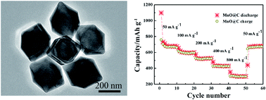
Trimanganese tetraoxide (Mn3O4) octahedra have been successfully synthesized by a one-pot hydrothermal process with the assistance of polyvinyl pyrrolidone (PVP). PVP is observed to be beneficial to control the morphology and agglomeration of octahedra. The growth mechanism has been proposed on the basis of control experiments. The manganese monoxide octahedra with a carbon coating (MnO@C) are generated after carbonizing the pyrrole carbon precursor. The as-prepared MnO@C exhibits a reversible capacity of 503 mA h g−1 after 100 cycles at a current density of 100 mA g−1 and a capacity of 526, 432 and 304 mA h g−1 at a current density of 200, 400 and 800 mA g−1, respectively. The MnO@C also shows much better cycling and rate performance compared with Mn3O4 due to the presence of the carbon coating, which efficiently buffers the volume change during the lithiation/delithiation and improves the electrical conductivity among manganese monoxide (MnO) octahedra.

Introduction

As advanced energy storage devices, lithium ion batteries (LIBs) are the most preferred power sources for electric vehicles (EVs) and hybrid electric vehicles (HEVs) due to their advantages of high voltage, high energy density and long life.1–3 At present, graphite has been widely used as a negative electrode material because it offers both electrochemical and mechanical stability. However, its theoretical capacity of only 372 mA h g−1 restricts its application in LIBs for high-power fields.4 In order to further improve the battery performances, research interests start to focus on exploring the negative electrode materials with high capacity to replace graphite.5,6 For example, transition metal oxides (TMOs) such as iron oxide (Fe2O3),7 nickel oxide (NiO),8 cobalt oxide (CoO)9 and copper oxide (CuO)10 have attracted great attention due to their higher theoretical capacity than graphite as reported by Poizot et al.11,12 However, most TMO electrodes suffer from several disadvantages such as poor electrical conductivity, high overpotential and large volume expansion.13,14 Therefore, many efforts have been devoted to achieve excellent performance in terms of high specific capacity, good cycling performance and reasonable rate performance in the past few years.

Recently, MnO has been regarded as a promising LIB negative electrode material because of its low conversion potential, low voltage hysteresis, natural abundance, environmental benignity, low cost, and relatively low electromotive force (EMF) (1.032 V vs. Li+/Li).15–17 However, similar to other pure TMO negative-electrode with volume expansion arising from the formation and decomposition of Li2O during the charge–discharge process, poor cycling performance is still a challenge to pure MnO negative electrode materials for practical applications.18,19 Therefore, various efforts have been devoted to studying the MnO/C composite electrode materials.20–22 Normally, the carbon coating is an effective way to obtain the enhanced electrochemical performance of MnO. Carbon coating could serve as a buffer to cushion the stress from the formation and decomposition of Li2O during cycling and to mitigate the agglomeration of MnO particles. Meanwhile, the carbon coating could enhance the electrical conductivity of the electrodes.21

Previous researches have indicated that the synthesis of nano/micron crystals with engineered shape and architecture is of great importance to their properties and applications.23,24 Up to now, the MnO/C composites with various morphologies and structures have been synthesized such as nanopeapods,25 nanorods,26 porous nanotubes,27 porous microspheres,28 nanowires,29 etc. For example, Su et al.13 prepared the MnO/C porous microspheres with a reversible capacity of 846 mA h g−1 at 100 mA g−1 as negative-electrode for LIBs through topochemical conversion of MnxZn1−xCO3 precursors by an ultrasonic-assisted co-precipitation method. Qiu et al.17 prepared the lantern like MnO@N–C negative electrode materials for LIBs with a reversible capacity of 640 mA h g−1 at 0.2 A g−1, which was fabricated from lantern-like MnCO3 coated with polydopamine precursor by calcining. Li et al.29 synthesized the MnO@C core–shell nanowires for LIBs application with a reversible capacity of 801 mA h g−1 at 500 mA g−1 by a hydrothermal-annealing method. All of these researches indicated that the design and fabrication of MnO@C with novel morphologies and structures had a profound effect on the performances of the electrode materials. Inspired by the above research studies, constructing manganese oxide nanocrystals coated with carbon will be beneficial for its LIB application. The downsizing crystals with carbon coating could not only buffer the volume expansion, but also increase the electrical conductivity of electrodes.

In this work, we demonstrate a novel route to fabricate MnO@C octahedra as negative-electrode for LIBs. The Mn3O4 octahedra are firstly prepared through the hydrolysis reaction of manganese acetate under a hydrothermal condition using polyvinyl pyrrolidone (PVP) as morphology directing agent. The influence of PVP and the formation mechanism have been proposed. The MnO@C octahedra are obtained after a carbonization process using pyrrole as a carbon source accompanied with the reduction of Mn3O4 to MnO. The electrochemical measurements demonstrate that the as-prepared MnO@C octahedra could serve as negative electrode materials for LIBs exhibiting excellent cycling and rate performances.

Experimental

Materials

Manganese acetate (Mn(CH3COO)2·4H2O, 99.0%), polyvinyl pyrrolidone (PVP, (C6H9NO)n, MW 40[thin space (1/6-em)]000), white polyvinylidene fluoride (PVDF (C2H2F2)n, MW 500[thin space (1/6-em)]000–700[thin space (1/6-em)]000), N-methyl-2-pyrrolidone (NMP) and pyrrole (C4H5N) were purchased from Sinopharm Chemical Reagent Co., Ltd, China. Carbon black, Li foil and Celgard 2300 were purchased from Hefei Kejing Material Technology Co., Ltd, China. LiPF6 (dissolved in ethylene carbonate, dimethyl carbonate, and ethylene methyl carbonate with a volume ratio of 1[thin space (1/6-em)]:[thin space (1/6-em)]1[thin space (1/6-em)]:[thin space (1/6-em)]1) was purchased from Shenzhen Biyuan Technology Co., Ltd, China. All the chemicals of analytical grade were used as-received without further purification.

Synthesis of MnO@C octahedra

In a typical process, PVP (0.5 g) and Mn(CH3COO)2·4H2O (4 mmol) were dissolved in 60 mL deionized water with magnetic stirring to form a transparent solution. After being stirred for 10 min, the mixed solution was transferred into a Teflon-lined stainless-steel autoclave with volume of 100 mL. This solution was subsequently sealed and heated at 150 °C for 3 h. The resultant precipitate was centrifuged and washed with deionized water and ethanol for five times, respectively, and then dried in an oven at 80 °C for 10 h for characterizations and further usage.

The carbon coating was carried out by mixing the as-prepared product of 1.5 g with 0.5 mL pyrrole in a stainless steel autoclave and heated in a furnace at 550 °C for 5 h.

Characterizations

X-ray powder diffraction (XRD) pattern was obtained by a Rigaku Dmax-rc X-ray diffractometer with Ni filtered Cu Kα radiation (V = 40 kV, I = 50 mA) at a scanning rate of 4° min−1. The microstructure of the final product was examined using a JSM-6700F field emission scanning electron microscope (SEM) at an accelerating voltage of 20 kV and electric current of 1.0 × 10⁻¹⁰ A, and a JEOL JEM-2100 high-resolution transmission electron microscope (HR-TEM) operated at 200 kV. The X-ray photoelectron spectra were recorded on a Kratos Analytical X-ray photoelectron spectrometer (XPS) using Al Kα (hv = 1486.6 eV) radiation as the excitation source under a condition of anode voltage of 12 kV and an emission current of 10 mA.

Electrochemical measurement

To prepare the working electrode, the active material, carbon black, and PVDF with a weight ratio of 8[thin space (1/6-em)]:[thin space (1/6-em)]1[thin space (1/6-em)]:[thin space (1/6-em)]1 were mixed in NMP to form a homogenous slurry, which was coated on a copper foil substrate and dried in a vacuum oven at 120 °C for 12 h. The CR2025-type cells were assembled using Li foil as counter and reference electrode, Celgard 2300 as separator, and 1 M LiPF6 as electrolyte. The assembly was performed in a glove box filled with argon atmosphere. As the active material, the weights of Mn3O4 and MnO@C on one working electrode are both 3.27 mg. The performance of the cell was evaluated galvanostatically in the voltage range from 0.02 to 3 V at various current densities on a LAND CT2001A battery test system.

Results and discussion

Characterizations of Mn3O4 and MnO@C octahedra

The morphology and microstructure of the as-prepared Mn3O4 products have been investigated by SEM and TEM. As shown in Fig. 1a, the SEM image indicates that the synthesized Mn3O4 is well-defined octahedral crystal with good dispersibility. The high magnification SEM image, Fig. 1b, shows that the surfaces of the octahedron are fairly smooth with no defects observed and the size of each edge is about 200 nm. The TEM images also confirm that the obtained sample has an octahedron structure with a size of about 200 nm (Fig. 1c). The corresponding selected area electron diffraction (SAED) pattern presents a single-crystal nature of the Mn3O4 octahedron (inset of Fig. 1c).30 The typical lattice fringe spacing is measured to be around 0.49 nm, corresponding to the (101) crystal plane of Mn3O4 (Fig. 1d).
image file: c5ra00830a-f1.tif
Fig. 1 SEM images (a and b) and TEM images (c and d) of Mn3O4 octahedra at different magnifications. The inset of (c) is the selected area electron diffraction (SAED) pattern of Mn3O4 octahedra.

The phase and purity of the as-prepared Mn3O4 is studied by XRD. As shown in Fig. S1, all diffraction peaks can be indexed to the tetragonal hausmannite structure of Mn3O4 (JCPDF 24-0734), which has a space group of I41/amd (It's one of the crystallographic space groups. I41 stands for one of the tetragonal crystal system symbols.) and lattice parameters of a = b = 5.762 Å and c = 9.47 Å. No peaks of any other phase are detected, illustrating the high purity of Mn3O4 prepared through the reaction of Mn(CH3COO)2 and H2O under the hydrothermal process.

A series of experiments by varying the reaction time and the amount of PVP were carried out to further reveal the formation process of Mn3O4 octahedra. Fig. S2 shows the time-dependent experiments confirming that the suspended particles begin to form during the hydrothermal reaction after 30 min and the morphology of octahedra with wide of 20–100 nm has been obtained (Fig. S2a). As the hydrothermal reaction continues, the size of the Mn3O4 octahedra increases and the number of small octahedra is reduced gradually (Fig. S2b–d). As the reaction time is prolonged to 1.5 h, most Mn3O4 octahedra with a size of about 160 nm are obtained with few octahedra smaller than 100 nm existing (Fig. S2d). When the reaction time is maintained for 3 h, the octahedra grown to ca. 200 nm and the small particles disappeared completely (Fig. 1a). PVP, a kind of nonionic surfactant, has been widely applied to assist the preparation of nano-/micro-scale materials.31–37 In order to investigate the effect of PVP on the formation of the final product, the control experiment is operated by varying the amount of PVP. Experimental results show that the product can be obtained in the absence of PVP, and the obtained sample aggregates are assembled by the nanowires and nanoparticles rather than the formation of octahedra morphology (Fig. S3a). The fibers are also Mn3O4, which has been identified by XRD and point EDX of SEM. When the added amount of PVP increases to 0.2 g, octahedra with size of 100–200 nm are obtained and most of the as-prepared octahedrons are agglomerated together, Fig. S3b. The well dispersed Mn3O4 octahedra are observed as 0.5 g PVP is added into the reaction (Fig. 1a). When the added amount of PVP increases to 1.0 or 1.5 g, octahedra can be obtained but a new octahedron will be grown on the surface of each octahedron (Fig. S3c and d). These results indicate that PVP plays an important role as the surface modifier to control the size and agglomeration of the Mn3O4 octahedra.

Based on the above experiment results, the growth process of the Mn3O4 octahedra can be proposed to “capping-molecule assisted growth” mechanism and the reactions for the formation of Mn3O4 octahedra are illustrated as follows:38

 
CH3COO + H2O → CH3COOH + OH (1)
 
6Mn2+ + 12OH + O2 → 2Mn3O4 + 6H2O (2)

Under hydrothermal condition, CH3COO is hydrolyzed to CH3COOH, resulting in an increased OH concentration. Then, the Mn3O4 is formed through the reaction of Mn2+, OH and O2. At the beginning of the reaction, the Mn3O4 crystal nucleus is formed through the above reactions. If PVP does not exist in the reaction system, the Mn3O4 crystal grows randomly into agglomeration without irregular shape, Fig. S3. As PVP is introduced into the reaction system, the Mn3O4 crystal nucleus can be capped effectively by PVP during the hydrothermal reaction process.39–41 After that, the interaction between PVP and various crystallographic planes of Mn3O4 can reduce the growth rate with high energy and enhance the growth rate with low energy by reducing the surface free energy, leading to the formation of Mn3O4 octahedra.

The MnO octahedra with carbon coating are obtained by a carbon coating process using pyrrole as carbon source. The morphology of the octahedra has no obvious variation during the coating process but a few of octahedra are fractured into small particles as shown in Fig. 2a. This phenomenon may be caused by the volume expansion of octahedron during the redox reaction between Mn3O4 and carbon. The MnO@C octahedra can be observed clearly in the TEM image (Fig. 2b), and a few of octahedra were smashed to smaller MnO@C nanoparticles with size of ca. 20–50 nm during the carbon coating process. The carbon layer with thickness of ca. 5–15 nm is deposited on the surface of MnO octahedra as shown Fig. S4 and is thicker than that (ca. 5 nm) of Fe3O4@C nanorods3b by the same carbonization process due to the larger particle size of Mn3O4 (ca. 300 nm). The typical lattice fringe spacing is measured to be 0.26 nm, corresponding to the (111) crystal plane of MnO (inset of Fig. 2b). In the XRD patterns, all peaks can be indexed well with cubic manganosite MnO (JCPDF 07-0230) and no other diffraction peak is observed (Fig. 2c), suggesting that Mn3O4 has been completely reduced to MnO during the carbon coating process and the carbon coated on the surface of MnO is amorphous structure. The XPS spectrum of MnO@C is recorded as shown in Fig. 2d to investigate the oxidation states of Mn in the product. The binding energies of Mn 2p3/2 and Mn 2p1/2 at 641.2 and 652.8 eV, respectively, are attributed to the characteristic binding energy peaks of MnO, which is in agreement with those of the previous literature.42,43 The XRD and XPS results confirm that Mn3O4 has been completely reduced to MnO through carbon coating process.


image file: c5ra00830a-f2.tif
Fig. 2 (a) SEM images and (b) TEM microstructures of as prepared MnO@C octahedra; (c) XRD pattern and (d) XPS spectra of MnO@C octahedra.

Electrochemical performance of MnO@C octahedra

For a better understanding of the as-prepared MnO@C octahedra to serve as negative-electrode in LIBs, the electrochemical performances were investigated. The working electrodes are also fabricated from the as-prepared Mn3O4 octahedra for comparison. Fig. 3a and b shows the selected discharge/charge curves of Mn3O4 and the MnO@C octahedra at a current density of 100 mA g−1 between 0.01 and 3 V, respectively. In the first discharge curve as shown in Fig. 3a, the Mn3O4 sample shows a voltage decrease to 0.37 V, corresponding to the insertion of Li ions into Mn3O4 to form LixMn3O4. The plateau at 0.37 V can be assigned to the reduction of Mn3+ and Mn2+ to Mn0.44,45 The first charge curve shows a slope from 1.0 to 1.5 V, indicating the oxidation of Mn0 to Mn2+. For the MnO@C sample, the first discharge curve shows a plateau at 0.25 V due to the reduction of Mn2+ to Mn0.46 The voltage plateau is at about 1.3 V during the charge process, attributing to the oxidation from Mn0 to Mn2+.47 The first discharge specific capacities of Mn3O4 and MnO@C are 1276 and 1098 mA h g−1, respectively, which are higher than that of their theoretical capacities (937 mA h g−1 and 755 mA h g−1). The enhanced capacity in the Mn3O4 and MnO@C can be attributed to the decomposition of electrolyte and the formation of SEI films.48 The component of the films mainly includes a variety of Li salts, whose formation could also consume Li from the electrode in the cells.49 Though the capacity of the first discharge for MnO@C is lower than that for the Mn3O4 sample arising from a higher theoretical capacity of the Mn2O3 (1018 mA h g−1) than that of MnO (755 mA h g−1), from the second discharge/charge cycle, the MnO@C shows good capacity retention due to the efficient buffering effect of the carbon coating on the volume change and the enhanced electrical conductivity supplied by the surface carbon layer. In addition, the initial coulombic efficiencies (CE) are 68.5% and 48.6% for MnO@C and Mn3O4, respectively. The large first cycle irreversible capacity may be attributed to the formation of SEI layer and pulverization of the active materials.50
image file: c5ra00830a-f3.tif
Fig. 3 Galvanostatic discharge/charge curves of the 1st, 2nd, 5th, and 80th cycles for (a) Mn3O4 and (b) MnO@C octahedra at a current density of 100 mA g−1.

Fig. 4a presents the cycling performances and CE of Mn3O4 and MnO@C materials at the charge and discharge current density of 100 mA g−1. The MnO@C shows favorable cycling stability and delivers a stable reversible capacity of 503 mA h g−1 after 100 cycles. The CE of MnO@C quickly reaches 96.5% in the second cycle, and even in the subsequent cycles, it still remains more than 98%. For the Mn3O4 sample, although the first discharge capacity reaches 1276 mA h g−1, the reversible capacity decreases successively to ca. 300 mA h g−1 after 20 cycles, and it needs more cycles (after 20 cycles) to reach a stable CE above 98%. The better cycling stability and higher capacity retention of the MnO@C than those of Mn3O4 indicates that the carbon coating significantly improves the cycling performance. In addition, the reversible capacity of the as-prepared MnO@C is higher than that of the reported MnO/C powders (470 mA h g−1 after 50 cycles) obtained by the thermal treatment of the mixed MnCO3 and sucrose47 and the cycling performance is more excellent than that of the MnO@C nanoplates (563 mA h g−1 after 30 cycles), prepared via thermal treatment deposition of acetylene with the precursor of Mn(OH)2 synthesized by hydrothermal method.51 The rate capability of MnO@C is displayed in Fig. 4b. The MnO@C achieves reversible capacities of 682, 602, 526, 432 and 304 mA h g−1 at current densities of 50, 100, 200, 400 and 800 mA g−1, respectively. It is noted that when the current density is returned to 50 mA g−1 after the rate performance test, the reversible capacity returns back to 681 mA h g−1, suggesting that the high current charge–discharge process has little effect on the prepared negative electrode materials. In summary, although the theoretical capacity of Mn3O4 is much higher than that of MnO, the MnO@C exhibits higher reversible capacity than Mn3O4 after 100 cycles. It is believed that the carbon layer can efficiently buffer the volume change during the lithiation/delithiation process, and the carbon layer coated on the MnO surface is favorable to improve the electrical conductivity among the MnO particles, finally enhance the cycling and rate performances of MnO@C composites.21


image file: c5ra00830a-f4.tif
Fig. 4 (a) Cyclic performance and coulombic efficiency (CE) of Mn3O4 and MnO@C octahedra at the current density of 100 mA g−1, and (b) rate performance of MnO@C octahedra.

Conclusions

In conclusion, a facile approach has been demonstrated to fabricate the Mn3O4 and Mn@C octahedra assisted by PVP as surfactant and used as negative-electrode in LIBs. The introduced PVP as a surfactant during hydrothermal system is crucial to control the morphology and dispersity of Mn3O4. The formation mechanism of the octahedron morphology has been discussed based on the experimental results. The as-prepared MnO@C octahedra after a carbonization process exhibit a remarkable enhancement of electrochemical properties including cycling and rate performances compared to Mn3O4 octahedra.

Acknowledgements

This work was supported by the Independent Innovation Foundations of Shandong University (2012ZD001, 2012JC013). The authors also acknowledge the financial supports from the Doctoral Program of Higher Education of China (20130131110068), New Century Excellent Talent Program (NCET-10-0545), State Education Ministry, and Natural Science Fund for Distinguished Young Scholars of Shandong (JQ201312). Z. Guo appreciates the support from National Science Foundation (NSF, CMMI 13-14486) of USA.

Notes and references

  1. J. Zhang, J. Ni, J. Guo and B. Cao, New J. Chem., 2014, 38, 3722 RSC.
  2. S.-K. Park, S.-H. Yu, S. Woo, J. Ha, J. Shin, Y.-E. Sung and Y. Piao, CrystEngComm, 2012, 14, 8323 RSC.
  3. (a) X. Su, Q. Wu, X. Zhan, J. Wu, S. Wei and Z. Guo, J. Mater. Sci., 2012, 47, 2519 CrossRef CAS; (b) C. Hu, S. Guo, G. Lu, Y. Fu, J. Liu, H. Wei, X. Yan, Y. Wang and Z. Guo, Electrochim. Acta, 2014, 148, 118 CrossRef CAS PubMed.
  4. Y. Gan, H. Gu, H. Xiao, Y. Xia, X. Tao, H. Huang, J. Du, L. Xu and W. Zhang, New J. Chem., 2014, 38, 2428 RSC.
  5. K. Zhong, B. Zhang, S. Luo, W. Wen, H. Li, X. Huang and L. Chen, J. Power Sources, 2011, 196, 6802 CrossRef CAS PubMed.
  6. H. Qu, S. Wei and Z. Guo, J. Mater. Chem. A, 2013, 1, 11513 CAS.
  7. A. Brandt and A. Balducci, J. Power Sources, 2013, 230, 44 CrossRef CAS.
  8. G.-P. Kim, S. Park, I. Nam, J. Park and J. Yi, J. Power Sources, 2013, 237, 172 CrossRef CAS PubMed.
  9. J.-S. Do and C.-H. Weng, J. Power Sources, 2005, 146, 482 CrossRef CAS PubMed.
  10. S. Ko, J.-I. Lee, H. S. Yang, S. Park and U. Jeong, Adv. Mater., 2012, 24, 4451 CrossRef CAS PubMed.
  11. P. Poizot, S. Grugeon, L. Dupont and J. M. Tarascon, Nature, 2000, 407, 496 CrossRef CAS PubMed.
  12. P. Balaya, H. Li, L. Kienle and J. Maier, Adv. Funct. Mater., 2003, 13, 621 CrossRef CAS PubMed.
  13. K. Su, C. Wang, H. Nie, Y. Guan, F. Liu and J. Chen, J. Mater. Chem. A, 2014, 2, 10000 CAS.
  14. S. Wang, Y. Ren, G. Liu, Y. Xing and S. Zhang, Nanoscale, 2014, 6, 3508 RSC.
  15. X.-H. Ma, Q.-Y. Wan, X. Huang, C.-X. Ding, Y. Jin, Y.-B. Guan and C.-H. Chen, Electrochim. Acta, 2014, 121, 15 CrossRef CAS PubMed.
  16. W. Luo, X. Hu, Y. Sun and Y. Huang, ACS Appl. Mater. Interfaces, 2013, 5, 1997 CAS.
  17. T. Qiu, J. Wang, Y. Lu and W. Yang, RSC Adv., 2014, 4, 23027 RSC.
  18. X. Q. Yu, Y. He, J. P. Sun, K. Tang, H. Li, L. Q. Chen and X. J. Huang, Electrochem. Commun., 2009, 11, 791 CrossRef CAS PubMed.
  19. K. Zhong, X. Xia, B. Zhang, H. Li, Z. Wang and L. Chen, J. Power Sources, 2010, 195, 3300 CrossRef CAS PubMed.
  20. B. Sun, Z. Chen, H.-S. Kim, H. Ahn and G. Wang, J. Power Sources, 2011, 196, 3346 CrossRef CAS PubMed.
  21. Y. L. Ding, C. Y. Wu, H. M. Yu, J. Xie, G. S. Cao, T. J. Zhu, X. B. Zhao and Y. W. Zeng, Electrochim. Acta, 2011, 56, 5844 CrossRef CAS PubMed.
  22. S.-R. Li, Y. Sun, S.-Y. Ge, Y. Qiao, Y.-M. Chen, I. Lieberwirth, Y. Yu and C.-H. Chen, Chem. Eng. J., 2012, 192, 226 CrossRef CAS PubMed.
  23. C. Yan and F. Rosei, New J. Chem., 2014, 38, 1883 RSC.
  24. S.-Z. Huang, J. Jin, Y. Cai, Y. Li, H.-Y. Tan, H.-E. Wang, G. V. Tendeloo and B.-L. Su, Nanoscale, 2014, 6, 6819 RSC.
  25. H. Jiang, Y. Hu, S. Guo, C. Yan, P. S. Lee and C. Li, ACS Nano, 2014, 8, 6038 CrossRef CAS PubMed.
  26. L. Su, Y. Zhong, J. Wei and Z. Zhou, RSC Adv., 2013, 3, 9035 RSC.
  27. G.-L. Xu, Y.-F. Xu, H. Sun, F. Fu, X.-M. Zheng, L. Huang, J.-T. Li, S.-H. Yang and S.-G. Sun, Chem. Commun., 2012, 48, 8502 RSC.
  28. X. Wang, S. Qiu, G. Lu, C. He, J. Liu, L. Luan and W. Liu, CrystEngComm, 2014, 16, 1802 RSC.
  29. X. Li, S. Xiong, J. Li, X. Liang, J. Wang, J. Bai and Y. Qian, Chem.–Eur. J., 2013, 19, 11310 CrossRef CAS PubMed.
  30. H. Gu, J. Guo, H. Wei, Y. Huang, C. Zhao, Y. Li, Q. Wu, N. Haldolaarachchige, D. P. Young, S. Wei and Z. Guo, J. Phys. Chem., 2013, 15, 10866 CAS.
  31. X. Wang, S. Qiu, J. Liu, C. He, G. Lu and W. Liu, Eur. J. Inorg. Chem., 2014, 2014, 863 CrossRef CAS PubMed.
  32. H. J. Jung, S. Lee, H. C. Choi and M. Y. Choi, Solid State Sci., 2013, 21, 26 CrossRef CAS PubMed.
  33. D. Y. Kim, W. Li, Y. Ma, T. Yu, Z.-Y. Li, O. O. Park and Y. Xia, Chem.–Eur. J., 2011, 17, 4759 CrossRef CAS PubMed.
  34. X. Han, L. Li and C. Wang, CrystEngComm, 2012, 14, 1939 RSC.
  35. B. Wiley, Y. Sun, B. Mayers and Y. Xia, Chem.–Eur. J., 2005, 11, 454 CrossRef CAS PubMed.
  36. F. Kim, S. Connor, H. Song, T. Kuykendall and P. Yang, Angew. Chem., Int. Ed., 2004, 43, 3673 CrossRef CAS PubMed.
  37. M. R. Buck, A. J. Biacchi, E. J. Popczun and R. E. Schaak, Chem. Mater., 2013, 25, 2163 CrossRef CAS.
  38. Y.-X. Zhang and Y. Jia, New J. Chem., 2013, 37, 3603 RSC.
  39. X. Zhang, Y. Xie, F. Xu, X. Liu and D. Xu, Inorg. Chem. Commun., 2003, 6, 1390 CrossRef CAS PubMed.
  40. J. Thirumalai and R. Chandramohan, J. Mater. Sci.: Mater. Electron., 2012, 23, 325 CrossRef CAS.
  41. M. R. Buck, A. J. Biacchi, E. J. Popczun and R. E. Schaak, Chem. Mater., 2013, 25, 2163 CrossRef CAS.
  42. B. Liu, X. Hu, H. Xu, W. Luo, Y. Sun and Y. Huang, Sci. Rep., 2014, 4, 4229 Search PubMed.
  43. Y. M. Sun, X. L. Hu, W. Luo and Y. H. Huang, J. Mater. Chem., 2012, 22, 19190 RSC.
  44. P. Poizot, S. Grugeon and J. M. Tarascon, J. Electrochem. Soc., 2002, 149, 1212 CrossRef PubMed.
  45. Y. Liu, X. Zhao, F. Li and D. Xia, Electrochim. Acta, 2011, 56, 6448 CrossRef CAS PubMed.
  46. X. Li, Y. Zhu, X. Zhang, J. Liang and Y. Qian, RSC Adv., 2013, 3, 10001 RSC.
  47. Y. Xia, Z. Xiao, X. Dou, H. Huang, X. Lu, R. Yan, Y. Gan, W. Zhu, J. Tu, W. Zhang and X. Tao, ACS Nano, 2013, 7, 7083 CrossRef CAS PubMed.
  48. L. Zhang, H. B. Wu, S. Madhavi, H. H. Hng and X. W. Lou, J. Am. Chem. Soc., 2012, 134, 17388 CrossRef CAS PubMed.
  49. J. Maier, Nat. Mater., 2005, 4, 805 CrossRef CAS.
  50. H.-W. Shim, A.-H. Lim, K.-M. Min and D.-W. Kim, CrystEngComm, 2011, 13, 6747 RSC.
  51. X. Zhang, Z. Xing, L. Wang, Y. Zhu, Q. Li, J. Liang, Y. Yu, T. Huang, K. Tang, Y. Qian and X. Shen, J. Mater. Chem., 2012, 22, 17864 RSC.

Footnote

Electronic supplementary information (ESI) available. See DOI: 10.1039/c5ra00830a

This journal is © The Royal Society of Chemistry 2015
Click here to see how this site uses Cookies. View our privacy policy here.