
 Open Access Article
 This Open Access Article is licensed under a
 Creative Commons Attribution 3.0 Unported Licence
Photodegradation of Rhodamine B over Ag modified ferroelectric BaTiO3 under simulated solar light: pathways and mechanism†
Yongfei
Cui
a,
Stephen M.
Goldup
b and
Steve
Dunn
*a
aMaterials Research Institute, School of Engineering and Materials Science, Queen Mary University of London, E1 4NS, UK. E-mail: s.c.dunn@qmul.ac.uk
bDepartment of Chemistry, University of Southampton, Southampton, SO17 1BJ, UK
First published on 24th March 2015
Abstract
The use of semiconductors with a ‘built in’ bias has now become of interest for a growing number of photoactive applications. Using a combination of spectroscopic techniques, gas chromatography in association with mass spectroscopy and NMR, we show that a sample of ferroelectric BaTiO3 decorated with nanostructured Ag denatures a standard dye molecule (Rhodamine B) via a photocatalytic oxidation mechanism. The photosensitized oxidation was inhibited due to band bending induced by ferroelectric polarisation. In the Ag–BaTiO3 system we find a slight hypsochromic wavelength shift during the initial stages of degradation (only 3 nm before 80% degradation percentage) and associate this shift with the cleavage of the chromophore structure which pre-empted deethylation. This shift in maximum absorption of the dye molecule did not occur until the later stages of molecule fragmentation. Our major identifiable breakdown intermediate was benzoic acid. A lack of other identifiable fragments during the breakdown of the dye is associated with retention of these fragments on the catalyst as full mineralisation of the dye liberates CO2.
Introduction
Semiconductor photocatalysis has received significant attention due to potential applications in environmental remediation1–3 and as a possible alternative to provide future energy security i.e. to produce solar fuels. The hazardous organic compounds in industrial effluent can be decomposed through a series of chemical redox reactions driven by photoexcited charge carriers in an excited semiconductor. A number of previous publications have described the reaction pathways that have resulted in some widely accepted reaction schemes.4–6 These reactions can be broadly divided into two mechanisms depending on the process of charge carrier generation and are termed photocatalytic oxidation (PCO) and photoassisted oxidation (PAO).5 Photocatalytic oxidation can occur when the semiconductor is exposed to super-band gap irradiation. Electrons and holes are formed directly in the conduction and valence band on interaction with incident photons. Photosensitized oxidation occurs when sub-band gap light is used. In this instance the organic dye is excited resulting in the injection of carriers (normally an electron) into the semiconductor. This occurs when the conduction band potential of the semiconductor is below the LUMO of the dye molecule, or chemisorbed molecules such as oxygen molecules followed by the formation of oxidative radicals.A large number of semiconductor photocatalytic systems have been developed and there are is a growing body of understanding pertaining to these systems.7–11 In addition to the traditional semiconductor systems, a new and interesting group of materials that are proving of increasing and significant interest are ferroelectric materials. This class of material, capable of developing an internal electric field due to the asymmetry in the crystal lattice show unique properties in photochemistry.12–15 It has been demonstrated that the spontaneous polarisation in ferroelectrics lead to charge carrier separation16 and that this is manifested as spatially selective redox chemistry. In addition, the spontaneous polarisation induced surface charge can be screened by adsorbing charged molecules from atmosphere. This leads to the formation of a strong Stern layer.17 This Stern layer can influence the bond structure of an adsorbed or chemisorbed molecule which may lead to a change in bond strength.18,19 These unique properties of a ferroelectric can overcome the common drawbacks in other catalytic systems, through inhibiting charge carrier recombination.20
In 2013 (ref. 21) we demonstrated that the presence of Ag on the surface of a ferroelectric phase of BaTiO3 could significantly enhance photocatalytic degradation of dye molecules. We fully characterised the Ag–BaTiO3 system and readers are encouraged to review our earlier work for the details of synthesis and analysis of material presented in this publication. Additionally we demonstrated that there is an influence of the ferroelectric nature of BaTiO3 by comparing systems of different crystal structures. When the BaTiO3 catalyst had a high ferroelectric tetragonal phase there was a three times increase in decolourisation rate compared to when the non-ferroelectric cubic phase was predominant.21 We stated that this enhancement was due to the internal dipole of the ferroelectric assisting separation of excited charge carriers and the tight Stern layer on the surface of BaTiO3.21 These findings demonstrate a promising future for ferroelectric materials as photocatalysts.
The current state of the art expresses a variety of reaction intermediates associated with different reaction pathways for the chemical degradation of dye molecules in a photocatalytic system. There has been a focus on determining the reaction intermediates from Rhodamine B, a common target dye, with the results being widely reported.22–31 Among these reports, a range of catalysts such as NaBiO3,22 Bi2WO6,23,26,31 in addition to TiO2 based catalysts,25,28–30 have been investigated and show different degradation pathways and chemical intermediates. In addition to the range of catalysts generating different reaction intermediates, changes in the surface state, crystalline structure and morphologies of the photocatalysts32 have also been demonstrated to influence the degradation process.30,33 However, to date there has been no contribution regarding the degradation pathway for a target dye molecule when a ferroelectric catalyst is used.
Here we investigate the degradation products formed during the photochemical reaction with a modified ferroelectric catalyst (Ag:BaTiO3) addressing the interesting question – does the spatial separation of photoinduced carriers influence the reaction pathway? It should also be noted that the presence of nanostructured silver on the surface of the BaTiO3 may also influence the reaction pathway through the interaction with a surface plasmon or photoassisted oxidation into the semi-conductor. A number of studies on traditional semi-conductor systems provide an insight into the reaction pathway when oxidation and reduction are not separated at the interface. Our focus is on the reaction with RhB under simulated solar light over our ferroelectric catalyst. The products of the reaction were evaluated using UV-vis spectroscopy, 1H nuclear magnetic resonance (1H NMR) and gas chromatography mass spectrometry (GC-MS). To verify our methodology, we employ the widely used photocatalyst TiO2 (P25) as a reference following the same experimental methods we have used or BaTiO3 to verify our procedures and demonstrate context to the existing literature.
Experimental methods
Ag modified BaTiO3 (termed Ag-BTO) was prepared and characterised as described in our previous publication.21 In summary we used BaTiO3 powder supplied by Sigma (99.9% trace metal basis <2 μm), followed by heat treatment at 1200 °C for 10 hours and photochemical silver deposition (UV irradiation for 30 seconds and Ag nanoparticles around 5–10 nm formed).0.15 g of Ag-BTO was loaded into 50 ml of 10 ppm Rhodamine B dye solution (RhB, Sigma, 99.9%). The dye solution and catalyst suspension was kept in the dark with gentle stirring for 30 min to obtain adsorption–desorption equilibrium. Photochemical degradation was performed under a solar simulator (Newport, class ABB) fitted with an AM 1.5G filter at a distance of 17 cm from the irradiation source giving a solar flux of 1sun (100 mW cm−2). During the degradation process, 2 ml aliquots of solution were taken for sampling at fixed intervals during the degradation process. The aliquot of solution and catalyst powder was then separated by centrifugation at 4000 rpm for 30 min. The optical absorption of the obtained dye solution was measured using a PerkinElmer Lambda 950 UV-vis spectrophotometer. When illuminating the sample with a spectrum other than AM 1.5G optical filters termed, UV block (UQG Optics LTD, UV blocking, 50 mm × 50 mm, 1.1 mm) and visible-block (UQG Optics LTD, Schott UG1, 50 mm × 50 mm, 2 mm) were placed between the irradiation source and dye catalyst suspension. The flux of incident light was maintained when filters were used by adjusting the solar simulator output. The zeta potential of photocatalysts was determined with Zetasizer Nano(Malvern co.uk) by dispersing amount of catalyst powder in aqueous solutions with different pH ranging from acidic to alkalinic.
Proton NMR spectrums of the dye solution were obtained using a Bruker NMR spectrometer operating at 600 MHz at 300 K. The samples for NMR analysis were prepared using the following methodology: 200 ml of 10 ppm RhB solution was mixed with 0.6 g catalysts, followed by dark-equilibrium for 1 hour, irradiation under solar light for the appropriate time, sampling, and centrifugation (as detailed earlier). The remaining solvent from the obtained solution (30 ml) was evacuated under reduced pressure at 45 °C using a rotary evaporator. The remaining residue was dissolved in 1 ml D2O ready for analysis.
Intermediates formed during degradation were identified by GC-MS (Agilent GC-MS, a 6890 gas chromatography interfaced with 5973 Mass Selective Detector). To improve the signal to noise values from the GC-MS, the initial concentration of RhB was increased from 10 ppm to 50 ppm, all other experimental parameters remained the same. The pH of the solution was then adjusted by 1 M HCl to 3.0 and the aqueous solutions were extracted bydichlromethane (DCM, Reagent Degrade) three times. This solution was then dehydrated by anhydrous sodium sulphate and solvent removed by rotary evaporation. After the residue was dissolved in 1 ml DCM, 0.5 ml N,O-bis(trimethylsilyl)trifluoroacetamide (BSTFA, Sigma, >99%) was added and the resulting solution was kept at 50 °C for 30 min to drive trimethylsilylation.
Results and discussion
Adsorption of RhB molecules onto the surface of catalysts
It is understood that the heterogeneous photodegradation process can be divided into five steps:4,34(1) Transfer the organic reactants from the bulk liquid to the surface region of catalysts.
(2) Adsorption of the reactants onto the surface of photo-excited catalysts.
(3) Photocatalytic reactions of the adsorbed phases.
(4) Desorption of reaction products/intermediates from the surface.
(5) Transfer of the products/intermediates to the bulk liquid.
The adsorption of a dye molecule onto the catalysts surface is an important step that has implications for the rate of molecule breakdown and, therefore, the overall reaction rate.35 During the dark equilibrium phase dye molecules adsorb onto the surface of the catalyst and develop equilibrium with dye molecules in solution. The amount of dye adsorption on our catalyst system was determined by comparing the absorption intensity of dye solution before and after the equilibrium phase. Table 1 shows the BET surface area and dye adsorption for Ag-BTO.
| Catalysts | BET surface area (m2 g−1) | Dye adsorption scaled by surface area (%) |
|---|---|---|
| Ag-BTO | 0.61 | 7.48 ± 0.19 |
It can be seen that the Ag-BTO shows a significant enhancement in adsorption of RhB per unit surface area during the same equilibrium period when compared to TiO2 (0.25 ± 0.02% of dye per surface) absorbed (Table S1†). This difference is due to the polar nature of the ferroelectric catalyst which differentiates the ferroelectric and non-ferroelectric material. The spontaneous polarisation in a ferroelectric can induce macroscopic surface charges, which are then screened by adsorbing the external molecules and/or internal charge carriers.36–38 This results in a higher loading of dye molecules at the interface with a tightly bound Stern layer39 for a ferroelectric material. It has been shown, for example, that BaTiO3 can adsorb more ethanol on polar surfaces than on an unpolarized surface.40 This type of dye adsorption enhancement has also been reported in the other ferroelectric LiNbO3 system.20
Photodegradation of RhB under different irradiation conditions
While we have previously investigated the impact of ferroelectric crystal structures on Ag-BTO,21 in order to understand the impact of ferroelectric dipoles on reaction pathways the interaction between PCO and PAO must be determined. In order to achieve, this photocatalytic properties of Ag-BTO were assessed through degradation of RhB under full spectrum solar light, visible light and UV. The latter two irradiation conditions were obtained by passing the solar light through optical filters. The irradiation spectra of the different test conditions are shown in Fig. S1.† The degradation profile for Ag-BTO under the different illumination sources is shown in Fig. 1.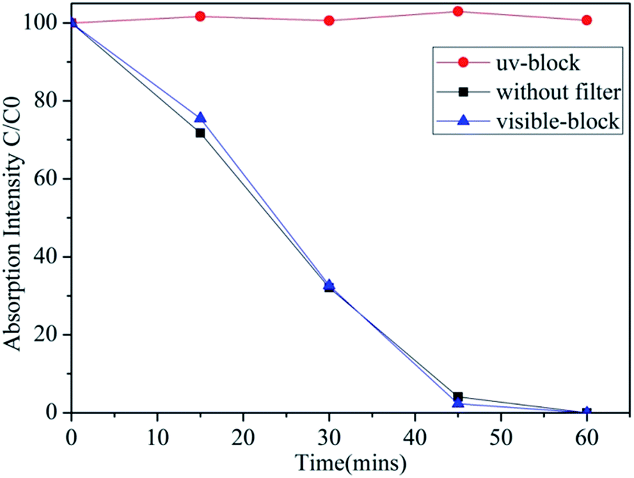 | ||
| Fig. 1 Photodegradation of RhB using Ag-BTO under simulated solar light, visible light and UV light. After UV light was blocked, the catalyst hardly showed any photocatalytic activity. | ||
In the case of our Ag-BTO system the results do not support the hypothesis that both sub and super band gap illumination are driving the reaction. As shown in Fig. 1, after the UV component of the full solar spectrum was blocked, there was negligible degradation of the dye throughout the course of the experiment period while the photodegradation profiles of full spectrum solar illumination and visible-light filter block almost overlap. This illustrates that in the Ag-BTO system, visible light hardly contributes to the degradation and only UV excited charge carriers are participating in the degradation reaction. The photoassisted oxidation process is hindered with respect to the direct photocatalysed. In comparison, for a standard TiO2 system, both visible light driven photosensitized oxidation and UV driven photocatalytic oxidation have been shown to coexist during the degradation process, shown in Fig. S2,† which is consistent with previously reported results.41
It is known that the conduction band gap position of the semiconductor is required to be lower than the lowest unoccupied molecular orbital (LUMO) of the dye to make electrons transfer successful for photoassisted oxidation. The structure of RhB is accepted to give the LUMO and HOMO positions at 1.1 eV and −1 eV versus NHE.42 In terms of the band structures of a semiconductor the specific band position of the semiconductor can be calculated according to the empirical equation:43,44
| ECB = X − Ee − 0.5Eg | (1) |
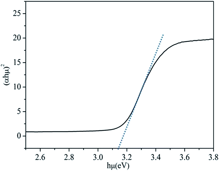 | ||
| Fig. 2 Tauc plot for Ag-BTO using the relationship between the square of αhμ versus photon energy for a direct semiconductor system. By extrapolating of the linear portion we determine the band gap to be 3.14 eV. | ||
Table 2 shows the adapted and calculated values for the band edge positions using eqn (1). The energy level diagrams of the Ag-BTO catalytic systems from Table 2 are shown schematically in Fig. 3. In Fig. 3 we demonstrate the proposed reaction scheme. When Ag-BTO was dispersed in the cationic dye RhB solution, the dye molecules will be attracted to the negative domains (c−) on the surface of the ferroelectric powder. The c+ surfaces will hold a net positive charge and so will not attract and absorb the cationic dye. As Ag is a conductor it will screen the charge in the ferroelectric but the whole c+ surface will have a net positive charge. The c− face is where holes accumulate leading to upward band bending, as shown in Fig. 3. Due to the proximity of the conduction band edge (−0.97 eV) and LUMO of RhB (−1 eV) and upward band bending of the ferroelectric c− domain. Our results support the hypothesis that this is enough of a barrier to prevent electron injection from the excited dye to the conduction band of BTO. This reduced injection of electrons will be manifested by a reduction in the rate of dye degradation. Once the electron transport cannot overcome the barrier formed at the catalyst surface and solution the photoassisted oxidation process will be suppressed. Accordingly visible light cannot contribute to the degradation process, which is consistent with the phenomenon observed in Fig. 1. This is different from a TiO2 system, where the photocatalytic oxidation and photoassisted oxidation reactions can coexist (see Fig. S2†).
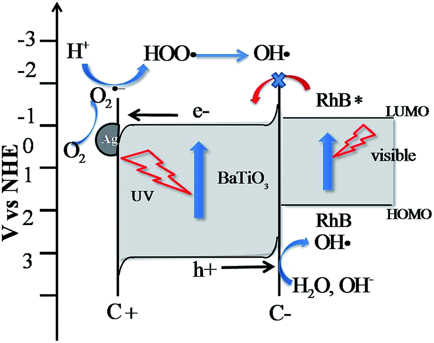 | ||
| Fig. 3 Calculated energy level diagram and proposed degradation reactions for the Ag-BTO system under simulated solar light. Photoassisted oxidation was hindered due to the barriers arising from band bending. | ||
Fig. 4(a) shows the UV-vis absorption spectra of RhB dye solution at different stages of decolourisation represented by the percentage of absorption at a fixed wavelength. The spectra shows a previously observed22,26,29,30 shift of wavelength during degradation of RhB. The change of maximum absorption wavelength as a function of decolourisation for the dye is shown in Fig. 4(b). There were two clear stages to the trend for the shift of wavelength. Up to 80% decolourisation there is only a slight shift in the wavelength of absorption (to a maximum of 2 nm) while in the second stage of reaction the maximum wavelength of absorption exhibited by the dye shifts significantly by 55 nm.
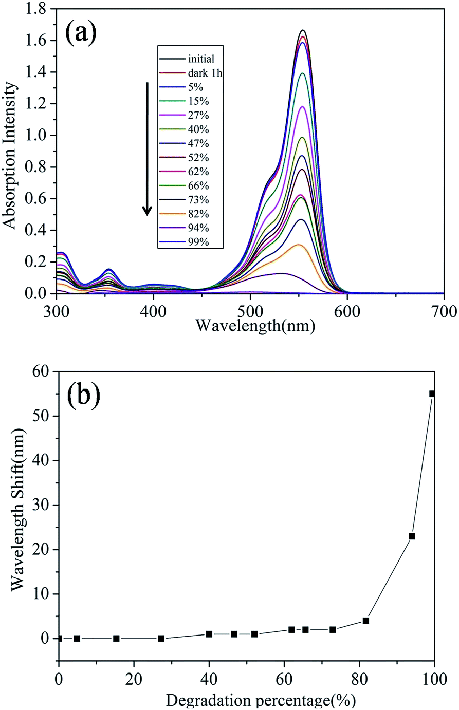 | ||
| Fig. 4 (a) UV-vis absorption spectra of RhB dye solutions with different degradation percentage in Ag-BTO system and (b) the maximum absorption wavelength shift of RhB as a function of degradation percentage in Ag-BTO system. | ||
The shift in absorption maximum wavelength has been associated with the deethylation process. The four ethyl group in RhB are removed one by one and a series of N-de-ethylated intermediates are formed.29 This deethylation process accompanies and competes with cleavage of the conjugated chromophore structure during the overall degradation process. Our Ag-BTO system shows a slight hypsochromic wavelength shift during the initial stage of degradation, indicating that cleavage of chromophore structure predominated.
In Ag-BTO system, as described above, only UV induced photocatalytic oxidation contributes to the whole process, and the oxidative radicals are generated from the reactions between charge carries from the catalysts and other species (O2, OH−, etc.). This is typical for systems undergoing such a photocatalysed reaction where the production of OH− and other active species is the initial step in photochemical reaction.22 In a photoassisted oxidation, the reactive species are produced near the adsorption site of the RhB molecules, where the excited dye molecules inject electrons into the semiconductor. Therefore, it is be easier for the reactive species to selectively attack the adsorbed group selectively. In Ag-BTO system, where only UV-induced photocatalytic oxidation exists, it is less likely that reactive radicals will selectively attack of adsorbed group (alkylamine group (–NEt2) in Ag-BTO, see Fig. S3†) which will lead to non-obvious deethlylation and a slight wavelength shift. This argument is consistent with the observations from previous work, where under UV irradiation the deethylation process was not so obvious as when under visible irradiation.21 The deethylation of the dye was regarded as initiated by visible light.44
To provide a reference and demonstrate the robustness of our test regimes, TiO2 was used as a model photocatalyst and used to compare products of the dye at the same decolourisation stage, shown in Fig. S4.† Overall we find that TiO2 system presents a similar degradation process,48 that is the cleavage of chromophore structure predominated over deethlylation. This observation is in accordance with the other reported results,25,30,49 where degradation of RhB with TiO2 under visible light was regarded to be mainly destruction of chromophore structure. Our findings indicate that the presence of the metal nanostructures and the ferroelectric nature of the catalyst have not significantly influenced the process of cleavage of the chromophore and indicates that our experimental procedure is robust.
1H NMR spectroscopy
To observe the structural changes of RhB during the degradation processes proton NMR analysis was performed. Six samples at the same percentage decolourisation, were evaluated using 1H NMR. Fig. 5 shows the NMR spectra for the degradation of RhB using Ag-BTO catalyst. The NMR signals from different protons in the RhB structure have been assigned peaks d, e, f, g, h, i and j represent aromatic hydrogen atoms Hd, He, Hf, Hg, Hh, Hi and Hj (Fig. S5†). The hydrogen atoms in the ethyl group of RhB structure contributed to the NMR peaks at δ 1.15–1.25 ppm and δ 3.6–3.6 ppm. In addition, there are a series of small peaks between peak a and peak b in the initial RhB sample. After careful examination of the NMR spectra of pure RhB and after catalyst loading, these peaks have been assigned to an impurity from of RhB and/or the NMR sample preparation process.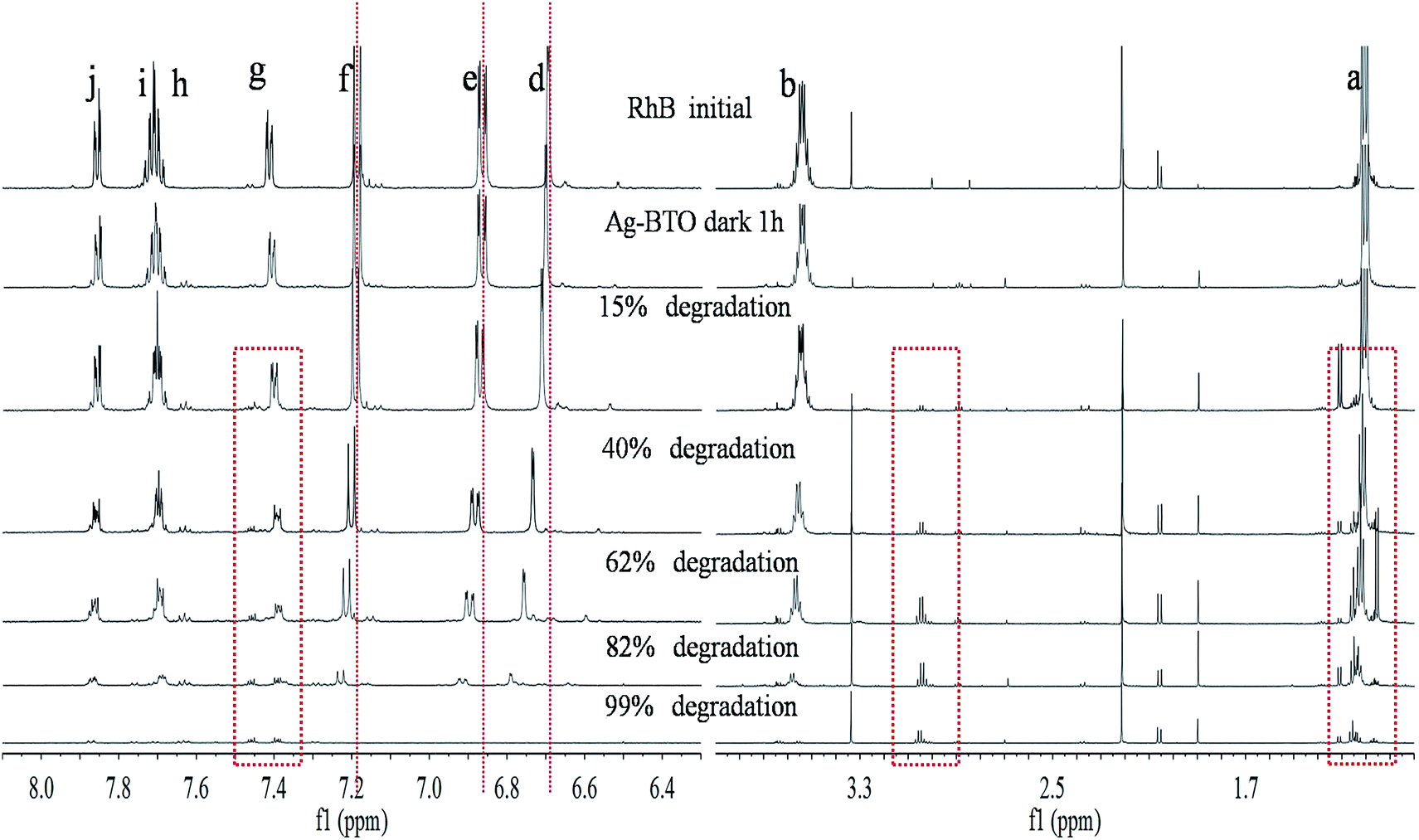 | ||
| Fig. 5 1H NMR spectra of samples with different degradation percentage with Ag-BTO. | ||
As the photodegradation progresses the intensity of the characteristic peaks associated with aromatic hydrogen atoms (peaks d–j) and ethyl group (peaks a and b) decrease while new peaks appear at δ 3.0–3.1 ppm and around peak a (δ 1.15–1.25 ppm) as highlighted in Fig. 5. The disappearance of characteristic peaks indicates the breakdown of chromophore structures and simultaneous removal of ethyl groups during the degradation process. The new peaks in the spectrum are associated with the intermediate products formed during degradation. In addition to the intensity decreasing for the characteristic peaks, a peak shift can be observed. As highlighted in Fig. 5, peaks d, e and f moved to a higher chemical shift while peaks g, h, I and j remain in place. If we consider the hydrogen atoms which these peaks represent in the RhB structure, this chemical shift could be associated with either the deethylation process or breakdown of the xanthene ring.
Fig. S6† shows the NMR spectra for the degradation of RhB for the TiO2 system. Being the same as Ag-BTO system, the characteristic peaks for aromatic hydrogen atoms and ethyl group disappeared. Meanwhile, new peaks appeared at δ 3.0–3.1 ppm and at δ 1.15–1.25 ppm were observed. The latter peaks were considered to be signals from –CH3 and analogous group. These features were consistent with the other RhB degradation works using TiO2 as catalysts.29,32
Identification of intermediates by GC-MS
Fig. 6 shows the gas chromatography of samples with irradiation for 10 and 90 min in Ag-BTO system. After discounting peaks associated with the impurities in the system (see Fig. S7†), new peaks (marked by ) were observed for the Ag-BTO system. These have been associated with intermediate products produced during the degradation process. The peaks at the retention time 5.82 min (Fig. 6(a)) and the peak with a retention time of 5.928 min (Fig. 6(b)) have been assigned to benzoic acid according to the mass fragmentation pattern. The small differences in retention time arise from individually sample injections.
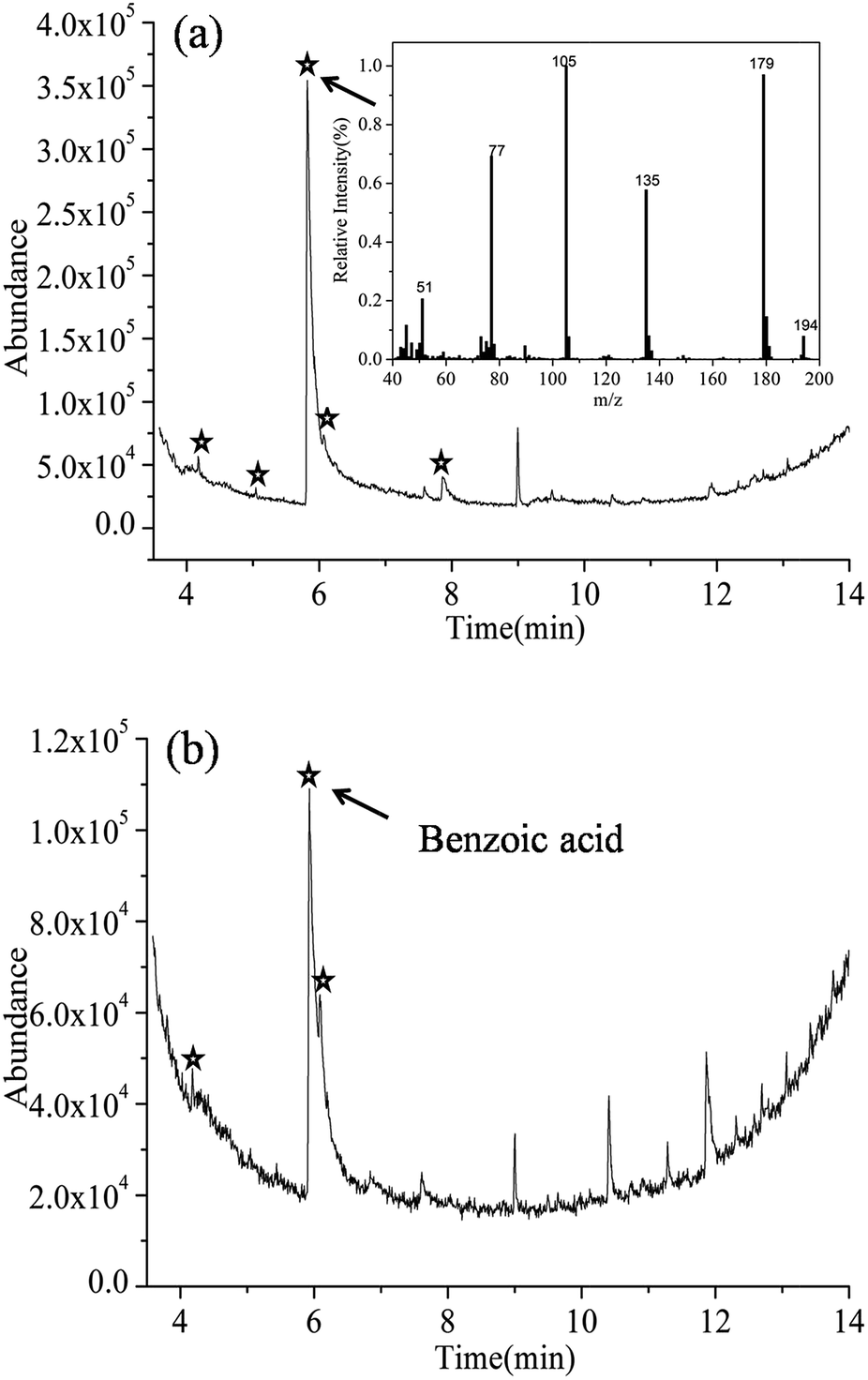 | ||
| Fig. 6 Gas chromatography of RhB with Ag-BTO-anneal after irradiation for (a) 10 min and (b) 90 min under solar simulator, with mass spectrum of the peak at 5.82 min (a), indicating the presence of benzoic acid. The peak at 5.928 min in (b) presents the same mass spectrum and can be assigned to benzoic acid as well. | ||
In addition to the benzoic acid peak, there are a new peaks at 4.172 min, 5.044 min, 6.068 min, 7.862 min in Fig. 6(a) and 4.179 min, 6.087 min in Fig. 6(b). However, we have not been able to assign a chemical structure to these peaks according to the mass fragmentation pattern. As they do not exist in the blank experiments and are not impurities so it is reasonable to assume that they are intermediate products in the degradation.
Comparing between Fig. 6(a) and (b), with the irradiation time increasing to 90 min, some new peaks observed in Fig. 6(a) have diminished while the intensity of benzoic acid peak dropped. The change in the pattern of the GC-MS relates the species that are in solution during the degradation of the RhB. The results shown here indicate that as the photochemical process proceeds the reaction intermediates are reacting to form a new mixture during degradation of the RhB. A number of publications have investigated the distribution of intermediates and degradation pathways for Rhodamine B22–31 using different catalysts. These previous works describe a number of discrepancies in the intermediates found during the degradation of RhB. However, phthalic acid and benzoic acid have been widely observed and have become the accepted, or the most probable, intermediates during the degradation of RhB.
In order to test this and support our observation, we performed experiments where we ran phthalic acid and benzoic acid as the target molecule through the GC-MS. From this we were able to determine the expected output for the two molecules using our GC-MS system. The retention time of phthalic acid and benzoic acid were found to be 8.644 min and 5.864 min (Fig. S8†). After examining the GC-MS results for the degradation of RhB over Ag-BTO, no peaks could be found that matched the peak position and mass fragmentation pattern of phthalic acid. This excluded the possibility of phthalic acid being produced as an intermediate when RhB is degraded over Ag-BTO. The peaks which have been assigned to benzoic acid in Fig. 6 are consistent with standard benzoic acid in terms of retention time and mass spectra. This further demonstrates the existence of benzoic acid as intermediate. Overall, the intermediates observed in Ag-BTO system are summarized in Table 3.
| Catalytic system Ag-BTO | Retention time of peaks obtained |
|---|---|
| T = 10 min | 4.172 min, 5.044 min, 5.82 min (benzoic acid), 6.068 min, 7.862 min |
| T = 90 min | 4.179 min, 5.928 min (benzoic acid), 6.087 min |
The intermediates in TiO2 system were also analysed (see Fig. S9 and 10†) following the same methodology. Ethylene glycol (at retention time 3.771 min) and benzoic acid (at retention time 5.8 min) have been identified as part of the intermediates in addition to a few other peaks unassigned in the sample at irradiation time 10 min. The confirmed species have been observed and reported as intermediates during degradation of RhB in TiO2 (ref. 32 and 50) and other catalytic systems,22,26 supporting the feasibility of the experimental process.
The impact of ferroelectric polarisation on surface chemistry has been extensively investigated, and it ranges from the varied desorption activation energy51,52 to the reactive sticking coefficient.40,53 Furthermore, the dipoles of ferroelectrics were demonstrated to bend the carbon dioxide molecule,19 and affect the adsorption configuration of OH˙ radicals.54 The polarisation-dependent adsorption has been observed in different species, e.g. water,53,55,56 alcohols,40,51,53 and acetic acid.52 In addition to the influence on adsorption, the interaction between the dipoles of adsorbed molecules and surface dipole in ferroelectrics can also affect the activation energy of the surface catalysed reactions.57 Based on previous work, it was expect that there will be some intriguing phenomenon on the ferroelectric surface when interacting with dye molecules, and that would lead to a varied degradation pathway. However, according to our results, it seems there is no significant change in the intermediates distribution and degradation pathway with respect to the nonpolar TiO2 system is seen for the ferroelectric system. There could be a number of reasons to account for this.
First, our ferroelectric system is ferroelectric powder, of which the polarisation orientation is not systematically controlled. Thus the potential effect of polarisation will not be evident as poled thin film or single crystal which is widely used in the investigation of polarisation effect.58 In addition, it was proposed that the geometry of transition metals on ferroelectric substrate plays an important role in enlarging or inhibiting the polarisation effect.59 When the metal clusters are too thick for their surface to be affect by the underlying polarisation, it will behave similarly to the other nonpolar systems. But in our system, the size of Ag nanoparticles is only 5–10 nm, which is not likely to block the effect from polarisation, although the exact critical thickness is not known. Thus the first reason is more likely. Nevertheless, our initial attempt to probe into the degradation mechanism, intermediates and pathways in degradation of RhB dye molecules using ferroelectric BaTiO3 provides a deeper understanding in ferroelectric catalytic system and add directions to the development of a new efficient photocatalyst.
Conclusion
We have used UV-vis spectroscopy, NMR and GC-MS to investigate the degradation process of Rhodamine B under simulated solar light with silver modified BaTiO3 as a photocatalyst. Our results indicate that a tight Stern layer is formed consisting of the dye cation and counter anions around the ferroelectric catalyst. The polarisation of the dipole associated with the ferroelectric forms band bending and this hinders the photosensitized oxidation process between adsorbed dye and the catalyst, such that we see no evidence of direct electron injection from the dye into the Ag-BTO. The hypsochromic wavelength shift of the maximum absorption peak shown by UV-vis demonstrates that the cleavage of the chromophore structure was the primary initial process of molecule breakdown. The use of NMR analysis further supported the hypothesis that during degradation there was cleavage of the chromophore structure followed by deethylation of the dye molecule. Analysis of the breakdown products shows that we have been able to identify benzoic acid as the main intermediate based on GC-MS analysis.Acknowledgements
The author, Yongfei Cui, would like to acknowledge Chinese Scholarship Council for supporting this work. Dr Joes Briscoe is acknowledged for helpful discussion in this work.References
- M. R. Hoffmann, S. T. Martin, W. Choi and D. W. Bahnemann, Chem. Rev., 1995, 95, 69–96 CrossRef CAS.
- P. K. J. Robertson, J. Cleaner Prod., 1996, 4, 203–212 CrossRef.
- D. S. Bhatkhande, V. G. Pangarkar and A. A. C. M. Beenackers, J. Chem. Technol. Biotechnol., 2002, 77, 102–116 CrossRef CAS PubMed.
- M. N. Chong, B. Jin, C. W. K. Chow and C. Saint, Water Res., 2010, 44, 2997–3027 CrossRef CAS PubMed.
- I. K. Konstantinou and T. A. Albanis, Appl. Catal., B, 2004, 49, 1–14 CrossRef CAS PubMed.
- U. G. Akpan and B. H. Hameed, J. Hazard. Mater., 2009, 170, 520–529 CrossRef CAS PubMed.
- S. J. A. Moniz, S. A. Shevlin, D. J. Martin, Z.-X. Guo and J. Tang, Energy Environ. Sci., 2015, 8, 731–759 CAS.
- H. Tong, S. Ouyang, Y. Bi, N. Umezawa, M. Oshikiri and J. Ye, Adv. Mater., 2012, 24, 229–251 CrossRef CAS PubMed.
- K. Maeda, J. Photochem. Photobiol., C, 2011, 12, 237–268 CrossRef CAS PubMed.
- H. Xu, S. Ouyang, L. Liu, P. Reunchan, N. Umezawa and J. Ye, J. Mater. Chem. A, 2014, 2, 12642–12661 CAS.
- A. Di Paola, E. García-López, G. Marcì and L. Palmisano, J. Hazard. Mater., 2012, 211–212, 3–29 CrossRef CAS PubMed.
- J. L. Giocondi and G. S. Rohrer, J. Phys. Chem. B, 2001, 105, 8275–8277 CrossRef CAS.
- J. L. Giocondi and G. S. Rohrer, Chem. Mater., 2001, 13, 241–242 CrossRef CAS.
- D. Tiwari and S. Dunn, J. Mater. Sci., 2009, 44, 5063–5079 CrossRef CAS.
- L. Li, P. A. Salvador and G. S. Rohrer, Photocatalysts with internal electric fields, Nanoscale, 2014, 6, 24–42, 10.1039/c3nr03998f.
- S. S. Roy, H. Gleeson, C. P. Shaw, R. W. Whatmore, Z. Huang, Q. Zhang and S. Dunn, Integr. Ferroelectr., 2000, 29, 189–213 CrossRef CAS PubMed.
- D. Tiwari, S. Dunn and Q. Zhang, Mater. Res. Bull., 2009, 44, 1219–1224 CrossRef CAS PubMed.
- A. L. Cabrera, F. Vargas and R. A. Zarate, J. Phys. Chem. Solids, 1994, 55, 1303–1307 CrossRef CAS.
- A. L. Cabrera, F. Vargas and J. J. Albers, Surf. Sci., 1995, 336, 280–286 CrossRef CAS.
- M. Stock and S. Dunn, J. Phys. Chem. C, 2012, 116, 20854–20859 CAS.
- Y. Cui, J. Briscoe and S. Dunn, Chem. Mater., 2013, 25, 4215–4223 CrossRef CAS.
- K. Yu, S. Yang, H. He, C. Sun, C. Gu and Y. Ju, J. Phys. Chem. A, 2009, 113, 10024–10032 CrossRef CAS PubMed.
- H. Fu, C. Pan, W. Yao and Y. Zhu, J. Phys. Chem. B, 2005, 109, 22432–22439 CrossRef CAS PubMed.
- Z. He, S. Yang, Y. Ju and C. Sun, J. Environ. Sci., 2009, 21, 268–272 CrossRef CAS.
- F. Chen, J. Zhao and H. Hidaka, Int. J. Photoenergy, 2003, 05, 209–217 CrossRef CAS.
- Z. He, C. Sun, S. Yang, Y. Ding, H. He and Z. Wang, J. Hazard. Mater., 2009, 162, 1477–1486 CrossRef CAS PubMed.
- P. Lei, C. Chen, J. Yang, W. Ma, J. Zhao and L. Zang, Environ. Sci. Technol., 2005, 39, 8466–8474 CrossRef CAS.
- J. Li, W. Ma, P. Lei and J. Zhao, J. Environ. Sci., 2007, 19, 892–896 CrossRef CAS.
- T. Wu, G. Liu, J. Zhao, H. Hidaka and N. Serpone, J. Phys. Chem. B, 1998, 102, 5845–5851 CrossRef CAS.
- Q. Wang, C. Chen, D. Zhao, W. Ma and J. Zhao, Langmuir, 2008, 24, 7338–7345 CrossRef CAS PubMed.
- H. Fu, S. Zhang, T. Xu, Y. Zhu and J. Chen, Environ. Sci. Technol., 2008, 42, 2085–2091 CrossRef CAS.
- J. Li, W. Ma, C. Chen, J. Zhao, H. Zhu and X. Gao, J. Mol. Catal. A: Chem., 2007, 261, 131–138 CrossRef CAS PubMed.
- G. Liu, X. Li, J. Zhao, H. Hidaka and N. Serpone, Environ. Sci. Technol., 2000, 34, 3982–3990 CrossRef CAS.
- J.-M. Herrmann, Catal. Today, 1999, 53, 115–129 CrossRef CAS.
- K. Vinodgopal and P. V. Kamat, J. Phys. Chem., 1992, 96, 5053–5059 CrossRef CAS.
- W. C. Yang, B. J. Rodriguez, A. Gruverman and R. J. Nemanich, J. Phys.: Condens. Matter, 2005, 17, S1415–S1426 CrossRef CAS.
- S. Dunn, P. M. Jones and D. E. Gallardo, J. Am. Chem. Soc., 2007, 129, 8724–8728 CrossRef CAS PubMed.
- S. Dunn, D. Tiwari, P. M. Jones and D. E. Gallardo, J. Mater. Chem., 2007, 17, 4460–4463 RSC.
- P. M. Jones and S. Dunn, J. Phys. D: Appl. Phys., 2009, 42, 065408 CrossRef.
- M. H. Zhao, D. A. Bonnell and J. M. Vohs, Surf. Sci., 2008, 602, 2849–2855 CrossRef CAS PubMed.
- J. Zhao, T. Wu, K. Wu, K. Oikawa, H. Hidaka and N. Serpone, Environ. Sci. Technol., 1998, 32, 2394–2400 CrossRef CAS.
- K. Hashimoto, M. Hiramoto and T. Sakata, Chem. Phys. Lett., 1988, 148, 215–220 CrossRef CAS.
- M. A. Butler and D. S. Ginley, J. Electrochem. Soc., 1978, 125, 228–232 CrossRef CAS PubMed.
- Y. I. Kim, S. J. Atherton, E. S. Brigham and T. E. Mallouk, J. Phys. Chem., 1993, 97, 11802–11810 CrossRef CAS.
- M. A. Butler, J. Appl. Phys., 1977, 48, 1914 CrossRef CAS PubMed.
- H. Fan, H. Li, B. Liu, Y. Lu, T. Xie and D. Wang, ACS Appl. Mater. Interfaces, 2012, 4, 4853–4857 CAS.
- R. G. Pearson, Inorg. Chem., 1988, 27, 734–740 CrossRef CAS.
- Y. Ma and J. Yao, J. Photochem. Photobiol., A, 1998, 116, 167–170 CrossRef CAS.
- Y. Fan, G. Chen, D. Li, Y. Luo, N. Lock, A. P. Jensen, A. Mamakhel, J. Mi, S. B. Iversen, Q. Meng and B. B. Iversen, Int. J. Photoenergy, 2012, 2012, 1–7 Search PubMed.
- T. Natarajan, K. Natarajan, H. Bajaj and R. Tayade, J. Nanopart. Res., 2013, 15, 1–18 CrossRef.
- Y. Yun, L. Kampschulte, M. Li, D. Liao and E. I. Altman, J. Phys. Chem. C, 2007, 111, 13951–13956 CAS.
- Y. Yun and E. I. Altman, J. Am. Chem. Soc., 2007, 129, 15684–15689 CrossRef CAS PubMed.
- D. Li, M. H. Zhao, J. Garra, A. M. Kolpak, A. M. Rappe, D. A. Bonnell and J. M. Vohs, Nat. Mater., 2008, 7, 473–477 CrossRef CAS PubMed.
- R. Hölscher, S. Sanna and W. G. Schmidt, Phys. Status Solidi, 2012, 9, 1361–1365 CrossRef PubMed.
- G. Geneste and B. Dkhil, Phys. Rev. B: Condens. Matter Mater. Phys., 2009, 79, 235420 CrossRef.
- S. Sanna, R. Hölscher and W. G. Schmidt, Phys. Rev. B: Condens. Matter Mater. Phys., 2012, 86, 205407 CrossRef.
- M. H. Zhao, D. A. Bonnell and J. M. Vohs, Surf. Sci., 2009, 603, 284–290 CrossRef CAS PubMed.
- S. Dunn, J. Appl. Phys., 2003, 94, 5964–5968 CrossRef CAS PubMed.
- K. Garrity, A. M. Kolpak, S. Ismail-Beigi and E. I. Altman, Adv. Mater., 2010, 22, 2969–2973 CrossRef CAS PubMed.
Footnote |
| † Electronic supplementary information (ESI) available: Dye adsorption on referenced sample P25, irradiation spectra under different wavelength conditions, zeta potential of Ag-BTO, photodegradation profiles, reaction mechanisms, UV-vis spectra and 1H NMR spectra in P25 system, GC-MS spectra and identified intermediates in P25 system and the comparison with standard compounds. See DOI: 10.1039/c5ra00798d |
| This journal is © The Royal Society of Chemistry 2015 |