
Preparation of nasal cavity-like SiC–Si3N4 foams with a hierarchical pore architecture
Duan Liab,
Elisângela Guzi de Moraesc,
Paolo Colombocd and
Zhijian Shen*ab
aDepartment of Materials and Environmental Chemistry, Arrhenius Laboratory, Stockholm University, S-106 91 Stockholm, Sweden. E-mail: shen@mmk.su.se; Fax: +46 8 152187; Tel: +46 8 162388
bBerzelii Center EXSELENT on Porous Materials, Stockholm University, S-106 91 Stockholm, Sweden
cDipartimento di Ingegneria Industriale, University of Padova, Via Marzolo 9, 35131 Padova, Italy
dDepartment of Materials Science and Engineering, The Pennsylvania State University, University Park, PA 16801, USA
First published on 9th March 2015
Abstract
Rigid SiC–Si3N4 foams with hierarchical porosity were prepared through protein-based gel-casting followed by radiant sintering in a modified spark plasma sintering (SPS) set-up. The porous bodies sintered at 1500–1700 °C for only 10 minutes achieved a compressive strength of 15–21 MPa while keeping a porosity of 60–70 vol%. Gradient porous structures, with pore sizes ranging between 1 to 100 μm, were intersected by the growth of hybrid SiC and Si3N4 nanowires inside the pores resulting in a nasal cavity-like appearance. Gas permeability at room temperature (25 °C) and 600 °C was evaluated. Darcian permeabilities and non-Darcian permeabilities of all the prepared foams at room temperature fell within (0.354–1.55) × 10−12 m2 and (1.60–6.33) × 10−8 m, respectively. Measurement of the Darcian and non-Darcian permeabilities at 600 °C were much higher, at 1.71 × 10⁻¹¹ m2 and 2.68 × 10⁻⁷ m, respectively. The microstructure, stability, gas flow properties and the green synthesis route reveal the potential of these ceramic foams to be used as industrial PM filters for airborne pollutions.
1. Introduction
PM2.5 issues have received extensive attention due to their detrimental influence on both human health and the environment.1–9 One possible solution for industry is to use ceramic filters for purification.9 Applications in such a harsh environment as steel or power plants lead to the following additional requirements for the materials of the filter: high temperature stability, oxidation and corrosion (chemical) resistance, good mechanical strength and low coefficient of thermal expansion (CET). Porous SiC–Si3N4 ceramics appear to be the most promising candidates targeted at such applications due to their inherent properties.10–15Foaming and sintering are two critical preparation steps for fabricating of stable and inert ceramic foams. Gel-casting of ceramic foams by using proteins as the gelling agent is a novel technique developed during the past decade.16–20 The basic principle is to solidify water-based ceramic suspensions into rigid bodies by gelation of proteins (such as ovalbumin).18,20 Compared with other foaming methods, the presented route is non-toxic, environment friendly (green), low-cost and widely available.17,19
Sintering is needed for receiving a stable consolidated filter material after the foaming processes. Conventional sintering techniques such as gas pressure sintering (GPS), pressureless sintering (PLS) and partial hot pressing (PHP) often require a high temperature (≥1800 °C) and long dwell time (a few hours) for strengthening SiC and Si3N4 foams even under the condition when sintering additives are added.21–23 Spark plasma sintering (SPS) provides the possibility for rapid and low-temperature densification due to effective heat transfer and electric field effect in certain cases.24–28 SPS has been proven to be a powerful tool for consolidating SiC and Si3N4 based materials.29–32 Rapid sintering of porous materials by intense thermal radiation based on a modified SPS set-up has recently been established by us.33
For gas filter applications, a gradient porous structure of the ceramic filters is preferred, as such structures must have sufficient low pressure drop with gas or particle mixed gas flow.34,35 Gas permeability is most often characterized by macroscopic measurement of the ease with which a gas driven by only a pressure gradient flows through the porous medium.33–43 Gas permeability is mainly controlled by the structural parameters such as pore characteristics (pore amount, pore size and distribution, pore shape), specific surface area and tortuosity.41 Different approaches have been developed to improve pore size and porosity.37–40,43 However, few studies are concerned about the high-temperature permeability that is crucial for the filtration of smoke dusts from steel/power plants that usually has a temperature higher than 600 °C.
In the present study, we utilized a low-cost and environment-friendly gel-casting method by adding egg white (mainly ovalbumin) in the aqueous slurry as both foaming agent and binder. In addition, this energy/time-saving sintering process based on a modified SPS set-up was employed to prepare stable SiC–Si3N4 foams. Randomly oriented SiC and Si3N4 nanowires were generated in situ in the porous structure for improving the filtration of micron sized particles. Catalytic ferrocene was used as Fe source for rapid and mass growth of the nanowires through the well-established vapor–liquid–solid (VLS) mechanism. Both room temperature (25 °C) and high temperature (600 °C) gas permeability was evaluated.
2. Experimental
2.1 Raw materials
Si3N4 powder (grain size d50 = 0.6 μm, purity ≥ 96 wt%, α phase ≥91.5%, Yantai Tomley Hi-tech New Materials Co., Yantai, Shandong, China) and SiC nanopowder (grain size d50 = 40 nm, purity ≥ 99.9 wt%, Shanghai Chao Wei Nanotechnology Co., Ltd., Shanghai, China) were used as the raw materials. Y2O3 (purity ≥ 99.99 wt%, Sigma Aldrich Chemie GmbH, Germany) and Al2O3 (purity ≥ 98 wt%, Sigma Aldrich Chemie GmbH, Germany) were selected as sintering additives. In a standard batch, the said materials were blended with mass ratio 1![[thin space (1/6-em)]](https://www.rsc.org/images/entities/char_2009.gif) :1:0.1:0.1 (Si3N4:SiC:Y2O3:Al2O3) and pre-mixed with 1 wt% (relative to the powder mixture) catalytic ferrocene powder (Fe(C5H5)2, purity ≥ 98 wt%, Sigma Aldrich Chemie GmbH, Germany). The powder mixture was ball milled in acetone for 3 h and the obtained slurry was then dried and sieved through a 36 μm screen.
:1:0.1:0.1 (Si3N4:SiC:Y2O3:Al2O3) and pre-mixed with 1 wt% (relative to the powder mixture) catalytic ferrocene powder (Fe(C5H5)2, purity ≥ 98 wt%, Sigma Aldrich Chemie GmbH, Germany). The powder mixture was ball milled in acetone for 3 h and the obtained slurry was then dried and sieved through a 36 μm screen.
2.2 Preparation of green foams
The preparation process of the green foams started with dispersion, followed by several steps shown in Fig. 1. 1 wt% polyacrylic acid (PAA, Sigma Aldrich Chemie GmbH, Germany) was used as dispersing agent with optimization. The foaming process was initiated by adding 1 wt% (relative to the powder mixture) nonionic surfactant polysorbate Tween@ 80 (Sigma Aldrich Chemie GmbH, Germany) with stirring at 1000 rpm for 5 min. Afterwards, 20 wt% (relative to the powder mixture) egg white powder (Sigma Aldrich Chemie GmbH, Germany) was introduced into the suspension as gelling agent and binder, and maintained at 60 °C for 30 min with vigorous stirring at 2000 rpm. Then the wet foam slurry was poured into pre-heated moulds and cooled to room temperature (20 °C). Complete drying was then conducted in a humidity chamber at 50 °C/50 RH% for 72 h and subsequently at 100 °C for 12 h. | ||
| Fig. 1 A flow chart describing the different steps for the preparation process of the ceramic foams, cf. the text. | ||
2.3 Sintering
After debinding at 600 °C for 300 min, rapid pressureless sintering was conducted in a modified SPS set-up (Dr Sinter 2050, Sumitomo Coal Mining Co., Tokyo, Japan) under vacuum. The green foams (labeled as SCSN-0) were loaded in a covered cylindrical graphite crucible with an inner diameter of 40 mm, an outer diameter of 48 mm and a height of 40 mm. The temperature was automatically raised to 600 °C over a period of 5 min and from there onwards it was monitored and regulated by an optical pyrometer. The pyrometer was focused on a graphite detail close to the sample and inside the crucible through a hole of ∼5 mm in diameter on the outer wall of the graphite crucible. Three sintering temperatures were tested at 1500, 1600 and 1700 °C and samples were labeled SCSN-1, SCSN-2 and SCSN-3, respectively. The sintering conditions are summarized in Table 1. All the samples were heated with a heating rate of 100 °C min−1 and held for 10 min at sintering temperature. Mechanically stable and rigid disk-shaped foams were obtained after cooling.| Sample | Sintering temperature (°C) | Total time consumed during sintering (min) | Bulk density (g cm−3) | Average pore sizea (μm) | Porosityb (%) | ||
|---|---|---|---|---|---|---|---|
| Cell | Window | Open | Total | ||||
| a Calculated according to mercury porosimetry results.b Calculated by assuming that the theoretical density of 100% dense SiC–Si3N4 composites is 3.4 g cm−3. | |||||||
| SCSN-0 | — | — | 0.73 | 102.7 | 53.0 | 56.8 | 78.5 |
| SCSN-1 | 1500 | 24 | 1.28 | 100.5 | 8.2 | 63.4 | 70.0 |
| SCSN-2 | 1600 | 25 | 1.37 | 45.3 | 2.1 | 52.6 | 67.2 |
| SCSN-3 | 1700 | 26 | 1.57 | 32.7 | 0.9 | 46.7 | 60.9 |
2.4 Characterization
The measurement of zeta potential was performed through a Zetasizer Nano ZS (Malvern Instruments, Worcestershire, UK). A refractive index of 2.60 and an absorbance of 0.2 were used. Deionized water was used as the continuous phase, where the values of 0.8872 mPa s for the viscosity at 25 °C, 1.33 for the refractive index and 78.5 for the dielectric constant were used. The measurements were performed in diluted suspensions (0.02 vol%), without or with different dispersants, in which the pH values were adjusted prior to the measurement by using either 0.1 M HNO3 or 0.1 M KOH and measured with a SevenMulti instrument equipped with an InLab Expert NTC30 electrode (Mettler Toledo, International Inc., Greifensee, Switzerland).Crystalline phase analysis was performed by a XRD diffractometer (PANalytical, Almelo, Netherlands) using CuKα radiation (λ = 1.5418 Å) at room temperature. The porosity of the samples with pore diameter ranging from 100 nm to 100 μm were determined using mercury intrusion porosimetry (Micromeritics AutoPore III 9410, Norcross, Georgia, USA). The surface tension and the contact angle of the mercury were set to 0.485 N m−1 and 130°, respectively. The microstructure of the foams was characterized by a field emission scanning electron microscope (FE-SEM, JSM-7000F, JEOL, Tokyo, Japan) and a LaB6 transmission electron microscope (TEM, JEM-2000FXII, JEOL Ltd., Tokyo, Japan) operated at 200 kV, equipped with an energy-dispersive X-ray spectroscopy (EDX) detector. TEM samples were prepared from the pulverized foam dispersed in ethanol. The compressive strengths of the foams were measured at room temperature (25 °C) using an universal testing machine (1121 UTM, Instron, Norwood, MA, USA). The cross-head speed was 1.0 mm min−1 and the compressive load cell was 5000 N. A minimum of five specimens with a nominal dimension of 10 × 10 × 10 mm3 were tested per data point (ASTM C133-97).
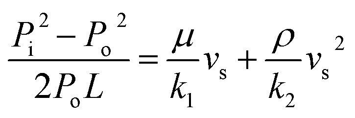
Gas permeability tests were carried out using an argon flow by a porosimeter, see Fig. 2. All the samples (SCSN-1, -2 & -3) were cut into disks with dimensions of Φ (20.5–22.5) mm × (7.6–7.7) mm and measured at room temperature (25 °C). The high temperature permeability of sample SCSN-1 was also measured at 600 °C (labeled as SCSN-1′). The Darcian and non-Darcian permeability parameters, namely k1 (m2) and k2 (m), were calculated from the measured flow rate and pressure drop using Forchheimer's equation:34,41
 | (1) |
| y = ax + bx2 | (2) |
 | (3) |
 | ||
| Fig. 2 Gas permeability measurement setups are illustrated for (a) room temperature (25 °C) and (b) high temperature (600 °C) recordings. The pressure drop to achieve a certain gas flow through a fixed filter area is monitored, cf. the text. | ||
3. Results and discussion
3.1 Dispersion and zeta potential
The first step for preparing ceramic foams is achieving an uniform dispersion of the ceramic powder in a liquid (typically water), which generally involves three steps: (i) wetting of the powder, (ii) breaking of agglomerates to form individual particles, and (iii) re-agglomeration. In the suspensions, fluid-dynamic forces exist between the particles due to electric charge effects and agglomerates are only generated when the repulsive forces are less than the attractive forces.44,45 One disadvantage occurring at the formation of these agglomerates, however, is that they might occasionally create abnormal voids/pores in the sintered ceramic foams if special care is not used.Ceramic powders with sub-micron size in dry form often contain hard agglomerates of primary particles.45 Therefore, in steps (i) and (ii) a complete dispersion of a mixed ceramic powder is a result of the complex balance of fluid-dynamics, gravity and interparticle electrostatic forces. Considering powders with multi-components, more difficulties might be expected in obtaining a well stabilized and homogeneous slurry due to hetero-coagulation and competitive adsorption.46 In conclusion, the steric or electrosteric stabilization requires strongly attached and dense layers of polymer or polyelectrolyte on the particle surfaces. Therefore, the use of a proper dispersing agent is necessary.
Zeta potential (ζ-potential) as a function of pH is usually measured for semi-quantifying the dispersion process. In our study, prior to foaming process, two types of dispersants with different concentrations were tested, namely polyacrylic acid (0.5 wt% PAA and 1 wt% PAA) and citric acid (0.5 wt% and 1 wt%). The measurements were performed in diluted suspensions containing the dispersants as well as 0.02 vol% SiC–Si3N4–Y2O3–Al2O3 powder mixture (mass ratio 1:1:0.1:0.1), and the results are presented in Fig. 3. As can be seen, the isoelectric point (IEP) is ∼3.0 for all cases, which is different from that usually reported for other multi-component mixes in the literature.46 This similarity of IEP is probably reflecting the same thin surface layer of soluble or insoluble silicon oxide/hydroxide found upon SiC and Si3N4 particles.45 In the pH range 3.0–10.0, the ζ-potential value became negative and decreased significantly from 0 to ∼−80 mV when pH increased, indicating stronger repulsive forces between particles. Considering the fact that >40 mV repulsive potential is required for a long-term stability, the use of 1 wt% PAA can be the optimal choice.47 PAA has a wider pH range (with >40 mV potential) than citric acid and was used in all our following foam preparations.
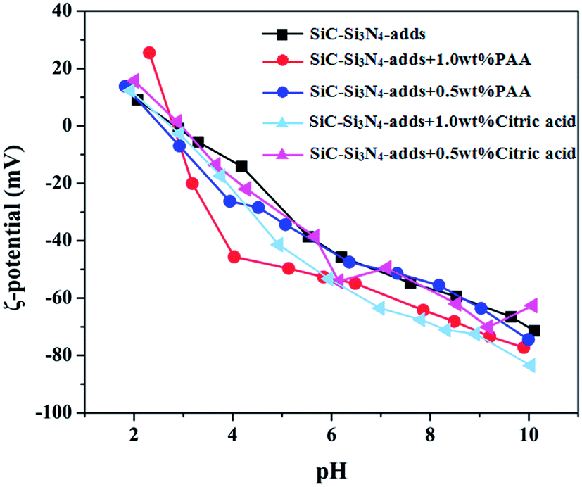 | ||
| Fig. 3 ζ-potential of the SiC–Si3N4 powder mixture with different types and concentrations of dispersants as a function of the pH. The dispersants were added as 0.5 and 1 wt% of polyacrylic acid (PAA) or citric acid. The isoelectric point (IEP) is around 3 for all, see discussion in the text. | ||
3.2 Sintering, necking, phase composition and mechanical strength
The hold time at high temperature was only 10 min and the entire sintering processes took less than 30 min, cf. sample parameters and denotations in Table 1. The compressive strength of the sintered foams as a function of porosity is given in Fig. 4. Before sintering, the green foam (SCSN-0) had a low compressive strength of 2.25 ± 0.25 MPa. After sintering, the compressive strength of the foams increased markedly with increasing sintering temperature. The observed high mechanical strength values can be attributed both to the formation of particle necks and thicker cell walls (see below). The neck-formation between adjacent particles is demonstrated in the TEM images of Fig. 4. The necks at particle connect points can be seen to growth wider with the increase in sintering temperature, resulting in better rigidity and strength of the cellular ceramic structure. This is in consistence with the results reported in Table 1, which shows that a higher sintering temperature resulted in a higher density and lower porosity of the foams. Thus, SCSN-3 (sintered at 1700 °C) possessed significantly higher strength of 21.40 ± 0.60 MPa at a porosity of 60.9 vol% than SCSN-2 (1600 °C) of 16.81 ± 0.82 MPa at 67.2 vol% or SCSN-1 (1500 °C) of 15.00 ± 1.84 MPa at 70.0 vol%. | ||
| Fig. 4 The recorded compressive strength of the sintered SiC–Si3N4 foams (at 1500–1700 °C) depicted as a function of total porosity. The strength increased and open porosity decreased by higher sintering temperature. The green foam is included for comparison (SNSC-0). TEM images are inserted to illustrate the formation of necking between particles after sintering. | ||
The XRD patterns revealed that all the sintered samples were predominantly composed of the precursor structures α-SiC and α-Si3N4, see XRD diagrams summarized in Fig. 5. However, the Al2O3 and Y2O3 precursor peaks, found before sintering, disappeared indicating the formation of liquid phase at high temperature that becomes a supercooled glassy phase after cooling. More intensive β-Si3N4 structure peaks relative the α-Si3N4 structure were observed in both SCSN-2 and SCSN-3 samples, due to the increase in the α- to β-Si3N4 transformation occurring at higher processing temperatures.
 | ||
| Fig. 5 XRD patterns of the precursor powder mixture, the green foam as well as the sintered SiC–Si3N4 foams at different temperatures. Note that the Y2O3 and Al2O3 sintering additives were only detected before the sintering and that the β-Si3N4 to α-Si3N4 ratio increased by temperature, cf. the text. | ||
Sintering of SiC and Si3N4 based materials often encounters difficulty due to their strong covalent bonding.48 Sintering additives, such as the Al2O3–Y2O3 system, are used to form an oxynitride liquid at high temperature and densification follows the liquid-phase sintering mechanism.21 However, consolidation of SiC and Si3N4 based ceramic foams by conventional methods requires hours for sintering even at >1800 °C.21–23 In the present study, the sintering temperatures were set from 1500 to 1700 °C. This is because that we employed a very effective method, sintering by intense thermal radiation (STIR), to densify the SiC–Si3N4 foams based on a pressureless SPS set-up as reported earlier by us.33 Sintering was assured by intense thermal radiation so that rigid foams could be obtained within minutes.
3.3 Nasal cavity-like structure with hierarchical pore architecture
The evolution of pore structure during foaming and sintering is illustrated by OM and SEM images in Fig. 6a–e. The optical pseudo-color images demonstrate the introduction of gas bubbles that are stabilized by the gel network, see Fig. 6a and b. The tendency of the suspension to remain in the wet foam condition, and the final cell size of the sintered foams, are mainly controlled by the processes of bubble expansion (Oswtald ripening) and coalescence taking place in the wet foams as well as liquid drainage from the foam's struts and cell walls.49 A cellular structure with interconnected pores was obtained after sintering, as can be seen from Fig. 6c–e. Pores in SCSN-2 and SCSN-3 foams have a more spherical geometry than in SCSN-1, and the cell walls of these foams sintered at higher temperature are thicker but still with some porosity (see from the insets). Two populations of pores were detected by mercury porosimetry in the sintered samples: the smaller with sizes below 10 μm (related to the residual porosity in the struts) and the larger with dimensions up to 100 μm (related to the cell windows and occasional macro-defects), as seen in Fig. 7 and listed in Table 1. Pore shrinkage took place with densification in all foams compared with the green foam (SCSN-0). | ||
| Fig. 6 Optical and SEM images showing pore evolution during foaming and sintering processes: (a) optical pseudo-color image of the bubbles immediately after gel-casting; (b) optical pseudo-color image of the bubbles after drying and removal of organics at 600 °C; (c)–(e) SEM images of the foam after being sintered at different temperatures: (c) 1500 °C, (d) 1600 °C & (e) 1700 °C. The insets in (d) & (e) show the cells and struts at higher magnifications. | ||
 | ||
| Fig. 7 Pore size distribution of the SiC–Si3N4 foams before and after being sintered at three different temperatures (1500, 1600 and 1700 °C). | ||
The formation of nanowires within the macro-pore framework can be seen from the higher magnification SEM images shown in Fig. 8. Numerous nanowires with a length of several tens of microns were grown in situ from initiation sub-micron iron-silicide droplets at the cell walls and foam struts, see Fig. 8a and d. The anisotropic growth and distribution of the nanowires divided the cells into smaller meshes with size ranging from less than 1 μm to 5 μm, which gives an impression of a nasal cavity-like structure, see Fig. 8b and e. A semispherical cap (droplet) was found in the tips of the nanowires, as seen in high SEM magnifications in Fig. 8c and f. Detailed microstructure characterized by TEM/EDX revealed that the nanowires have a diameter of 50 to 200 nm, see Fig. 9. Simultaneous EDX results show that the caps contained a silicide phase with variable iron content, SiFex, and that the bodies of the nanowires were composed either of Si–C–O or Si–N–O (see Fig. 9a and b). The analyzed nanowire volume is really small and the EDX did pick up some radiations from the Cu grid; thus, Cu-peaks are present in the nanowire EDX recordings. All these features reveal that the VLS mechanism is behind the formation of SiC and Si3N4 nanowires assisted by addition of the ferrocene catalyst.50–54 The oxygen content might come from additives, but more probably from the oxidized surface layers of SiC and Si3N4 precursor materials.51
 | ||
| Fig. 8 SEM images of the SiC–Si3N4 foams sintered (a)–(c) at 1600 °C and (d)–(f) at 1700 °C showing the nasal cavity-like structure discussed in the text. | ||
 | ||
| Fig. 9 TEM images of (a) SiC and (b) Si3N4 nanowires grown inside the SiC–Si3N4 pore framework sintered at 1700 °C. The inserted EDX results confirmed the VLS formation of hybrid SiC & Si3N4 nanowires with semispherical caps (droplets) of iron silicide in the tips. The Cu-signal is from the Cu-grid when recording the very small analyzed volume of the nanosized wires. | ||
At the end of the processing, therefore, the produced samples contained hierarchical pore architecture which was composed of: (a) macropores derived from the stabilized gas bubbles (of the order of a several tens of microns to a few hundred microns); (b) cell windows (of the order of 10–30 microns); (c) “pores” between the nanowires (of the order of less than 1 micron to 5 microns); and (d) the residual porosity in the struts (resulted from incomplete sintering). This size distribution enables the possibility for filtration of fine particles around PM2.5 level based on different filtration mechanisms.55
3.4 Permeability
Permeability is an important parameter for characterizing the efficiency of the filtration property.34 It normally predicts the pressure drop (or pressure gradient) necessary to achieve a specific gas flow rate for a fixed filter area.36 Darcy's law and Forchheimer's equation are the two most important expressions to describe the permeability, see eqn (1)–(3). Darcy's law considers only the viscous effects on the fluid pressure drop and establishes a linear dependence between the pressure gradient and the fluid velocity through the porous medium, and has been widely applied due to its simplicity. However, it fails to include the important contributions from inertia and turbulence when compared with Forchheimer's equation.35,40 In this study, we employed the more realistic and reliable Forchheimer's equation to calculate two permeability parameters: k1 (Darcian permeability, in dimensions of square length) and k2 (non-Darcian permeability, in dimensions of length) both at 25 °C and 600 °C, see eqn (3).The fitted Forchheimer's equation for all sintered samples (SCSN 1–3) and the calculated permeability values are given in Fig. 10a and b, respectively. At room temperature (25 °C); sample SCSN-1 displayed the highest Darcian (1.55 × 10⁻¹² m2) and non-Darcian permeability values (0.633 × 10⁻⁸ m), while sample SCSN-3 has the lowest values, being 0.354 × 10⁻¹² m2 and 1.60 × 10⁻⁸ m. This can be explained by the difference in their pore size and degree of open porosity, reported in Table 1, i.e. the permeability value increased with larger open porosity and pore size. This is in good agreement with previous studies.37,42
 | ||
| Fig. 10 (a) Experimental permeability data at 25 °C fitted according to Forchheimer's equation as a function of the fluid velocity; (b) the calculated permeability values. The results are discussed in the text and the sample with extraordinary good data is measured at 600 °C (SCSN-1′). | ||
Gas permeability of sample SCSN-1 at 600 °C was also measured (labeled as SCSN-1′). The aim was to examine the pressure drop in relation to gas flow at high temperature. Compared with the room temperature behavior, at 600 °C both of the Darcian and non-Darcian permeabilities increased quite significantly to 1.71 × 10⁻¹¹ m2 and 2.68 × 10⁻⁷ m, respectively, indicating that the gas fluid condition is improved at high temperature. This is probably due to the thermal expansion of the foams that generated larger pores to allow better gas penetration. More experiments will be conducted to assess the precise reason for the change in permeability occurring in the samples with varying temperature.
Filtration tests were conducted on SiC ceramic foams decorated with NWs, produced using a different route to the one proposed in this work but with a similar morphology.56 The results indicate that the filters removed the aerosol particulate (with particle diameter ranging from 8 to 280 nm) with an efficiency close to that of HEPA filters, with comparatively less resistance to air flow.
Overall, the permeability of SiC–Si3N4 ceramics is largely dependent on both open porosity and pore size. With the in situ growth of one-dimensional nanostructures from the foam struts and cell walls into the macroscopic cells, the permeability at room temperature was still comparable with the best available filters, and the comparison was even more favorable at 600 °C. The good high temperature permeability, the high mechanical strength and the superior chemical durability of SiC–Si3N4 ceramics suggests that these components with hierarchical pore architecture could find application in the filtration of particulate from hot gases in a harsh chemical environment.
4. Conclusions
In summary, we have designed nasal cavity-like SiC–Si3N4 foams with a hierarchical pore architecture. The macro-cellular interconnected cellular structure was formed by a protein-based gel-casting method. Hybrid SiC/Si3N4 nanowires were grown in situ on the cell walls when sintering at 1500 to 1700 °C by intense thermal radiation in the presence of a Fe-based catalyst. The obtained porous structures had an average cell size of the order of ∼100 μm, a cell windows size ranging from ∼10 to 30 μm and the foam struts and cell walls were decorated with nanowires, with a length of several tens of microns and an average diameter of ∼50 to 200 nm. The foams possessed an open porosity of 60 to 70 vol% and compressive strength of 15 to 21 MPa. The permeability, tested at room temperature (25 °C) and at 600 °C, indicated a good penetration capacity of the gas throughout the structure. The hierarchical pore architecture, gas permeability, good chemical and mechanical properties and green synthesis route of these components suggests their strong potential for application as PM2.5 filter for steel or power plants. Future work will be focused on the evaluation of their PM2.5 filtration efficiency.Acknowledgements
We acknowledge the financial supports by the Swedish Research Council (VR) and the Swedish Governmental Agency for Innovation Systems (VINNOVA) through the Berzelii Center EXSELENT on Porous Materials and by the Ministry of Science and Technology of the P. R. China through Sinosteel Corporation Luoyang Institute of Refractories Research. The support by European Commission through the Marie-Curie ITN project “Functional Nitrides for Energy Applications, FUNEA” (FP7-PITN-GA-2010-264873) is also appreciated. The authors would express their gratitude to Stefano Corradetti (INFN-LNL, Italy) and Murilo Daniel de Mello Innocentini (University of Ribeirao Preto, Brasil) for their assistance with permeability measurements. We also appreciated Prof. Thommy Ekström for his kind comments and suggestions.References
- R. D. Brook, B. Franklin, W. Cascio, Y. Hong, G. Howard and M. Lipsett, et al., Air pollution and cardiovascular disease: a statement for healthcare professionals from the Expert Panel on Population and Prevention Science of the American Heart Association, Circulation, 2004, 109, 2655–2671 CrossRef PubMed.
- D. Guan, X. Su, Q. Zhang, G. P. Peters, Z. Liu and Y. Lei, et al., The socioeconomic drivers of China's primary PM2.5 emissions, Environ. Res. Lett., 2014, 9, 024010 CrossRef.
- A. Yang, A. Jedynska, B. Hellack, I. Kooter, G. Hoek and B. Brunekreef, et al., Measurement of the oxidative potential of PM2.5 and its constituents: the effect of extraction solvent and filter type, Atmos. Environ., 2014, 83, 35–42 CrossRef CAS PubMed.
- Z. Cheng, J. Jiang, O. Fajardo, S. Wang and J. Hao, Characteristics and health impacts of particulate matter pollution in China (2001–2011), Atmos. Environ., 2013, 65, 186–194 CrossRef CAS PubMed.
- S. A. Guerra, S. R. Olsen and J. J. Anderson, Evaluation of the SO2 and NOX offset ratio method to account for secondary PM2.5 formation, J. Air Waste Manage. Assoc., 2014, 64, 265–271 CAS.
- J. Si, X. Liu, M. Xu, L. Sheng, Z. Zhou and C. Wang, et al., Effect of kaolin additive on PM2.5 reduction during pulverized coal combustion: importance of sodium and its occurrence in coal, Appl. Energy, 2014, 114, 434–444 CrossRef CAS PubMed.
- D. D. Parrish and T. Zhu, Clean Air for Megacities, Science, 2009, 326, 674–675 CrossRef CAS PubMed.
- C. Cao, W. J. Jiang, B. Y. Wang, J. H. Fang, J. D. Lang and G. Tian, et al., Inhalable microorganisms in Beijing's PM2.5 and PM10 pollutants during a severe smog event, Environ. Sci. Technol., 2014, 48, 1499–1507 CrossRef CAS PubMed.
- M. Fuji, Y. Shiroki, R. L. Menchavez, H. Takegami, M. Takahashi, H. Suzuki, S. Izuhara and T. Yokoyama, Fabrication of cordierite filter by in situ solidification for high temperature dust collection, Powder Technol., 2007, 172, 57–62 CrossRef CAS PubMed.
- Q. Liu, F. Ye, Z. Hou, S. Liu, Y. Gao and H. Zhang, A new approach for the net-shape fabrication of porous Si3N4 bonded SiC ceramics with high strength, J. Eur. Ceram. Soc., 2013, 33, 2421–2427 CrossRef CAS PubMed.
- W. Yang, F. Gao, C. Xu, G. Wei and L. An, Fabrication of Si3N4/SiC nanocomposites toughened by in situ formed low-dimensional nanostructures, Solid State Sci., 2010, 12, 1692–1695 CrossRef CAS PubMed.
- J. H. Shin, B. V. M. Kumar, J. H. Kim, S. H. Hong and R. Scattergood, Tribological properties of Si3N4/SiC nano-nano composite ceramics, J. Am. Ceram. Soc., 2011, 94, 3683–3685 CrossRef CAS PubMed.
- R. Arora and K. Balasubramanian, Hierarchically porous PVDF/nano-SiC foam for distant oil-spill cleanups, RSC Adv., 2014, 4, 53761–53767 RSC.
- F. L. Riley, Silicon nitride and related materials, J. Am. Ceram. Soc., 2000, 83, 245–265 CrossRef CAS PubMed.
- I. W. Chen and A. Rosenflanz, A tough SIAION ceramic based on alpha-Si3N4 with a whisker-like microstructure, Nature, 1997, 389, 701–704 CrossRef CAS PubMed.
- A. R. Studart, U. T. Gonzenbach, E. Tervoort and L. J. Gauckler, Processing routes to macroporous ceramics: a review, J. Am. Ceram. Soc., 2006, 89, 1771–1789 CrossRef CAS PubMed.
- S. Dhara, M. Pradhan, D. Ghosh and P. Bhargava, Nature inspired novel processing routes for ceramic foams, Adv. Appl. Ceram., 2005, 104, 9–21 CrossRef CAS PubMed.
- B. S. Murray and R. Ettelaie, Foam stability: proteins and nanoparticles, Curr. Opin. Colloid Interface Sci., 2004, 9, 314–320 CrossRef CAS PubMed.
- S. Dhara and P. Bhargava, Egg white as an environmentally friendly low-cost binder for gelcasting of ceramics, J. Am. Ceram. Soc., 2001, 84, 3048–3050 CrossRef CAS PubMed.
- O. Lyckfeldt, J. Brandt and S. Lesca, Protein forming – a novel shaping technique for ceramics, J. Eur. Ceram. Soc., 2000, 20, 2551–2559 CrossRef CAS.
- A. Diaz, S. Hampshire, J. F. Yang, T. Ohji and S. Kanzaki, Comparison of mechanical properties of silicon nitrides with controlled porosities produced by different fabrication routes, J. Am. Ceram. Soc., 2005, 88, 698–706 CrossRef CAS PubMed.
- B. K. Jang and Y. Sakka, Thermophysical properties of porous SiC ceramics fabricated by pressureless sintering, Sci. Technol. Adv. Mater., 2007, 8, 655–659 CrossRef CAS PubMed.
- J. F. Yang, T. Ohji, S. Kanzaki, A. Diaz and S. Hampshire, Microstructure and mechanical properties of silicon nitride ceramics with controlled porosity, J. Am. Ceram. Soc., 2002, 85, 1512–1516 CrossRef CAS PubMed.
- E. A. Olevsky and L. Froyen, Impact of thermal diffusion on densification during SPS, J. Am. Ceram. Soc., 2009, 92, S122–S132 CrossRef CAS PubMed.
- Z. Shen and M. Nygren, Kinetic aspects of superfast consolidation of silicon nitride based ceramics by spark plasma sintering, J. Mater. Chem., 2001, 11, 204–207 RSC.
- Z. J. Shen, Z. Zhao, H. Peng and M. Nygren, Formation of tough interlocking microstructures in silicon nitride ceramics by dynamic ripening, Nature, 2002, 417, 266–269 CrossRef CAS PubMed.
- M. Omori, Sintering, consolidation, reaction and crystal growth by the spark plasma system (SPS), Mater. Sci. Eng., A, 2000, 287, 183–188 CrossRef.
- Z. A. Munir, D. V. Quach and M. Ohyanagi, Electric current activation of sintering: a review of the pulsed electric current sintering process, J. Am. Ceram. Soc., 2011, 94, 1–19 CrossRef CAS PubMed.
- J. Wan, R. Duan and A. Mukherjee, Spark plasma sintering of silicon nitride/silicon carbide nanocomposites with reduced additive amounts, Scr. Mater., 2005, 53, 663–667 CrossRef CAS PubMed.
- M. Belmonte, J. González-Julián, P. Miranzo and M. I. Osendi, Spark plasma sintering: a powerful tool to develop new silicon nitride-based materials, J. Eur. Ceram. Soc., 2010, 30, 2937–2946 CrossRef CAS PubMed.
- D. S. Perera, M. Tokita and S. Moricca, Comparative study of fabrication of Si3N4/SiC composites by spark plasma sintering and hot isostatic pressing, J. Eur. Ceram. Soc., 1998, 18, 401–404 CrossRef CAS.
- M. Suganuma, Y. Kitagawa, S. Wada and N. Murayama, Pulsed electric current sintering of silicon nitride, J. Am. Ceram. Soc., 2003, 86, 387–394 CrossRef CAS PubMed.
- D. Li, E. G. Moraes, P. Guo, J. Zou, J. Z. Zhang, P. Colombo and Z. Shen, Rapid sintering of silicon nitride foams decorated with one-dimensional nanostructures by intense thermal radiation, Sci. Technol. Adv. Mater., 2014, 15, 045003 CrossRef.
- M. Scheffler and P. Colombo, Cellular ceramics: structure, manufacturing, properties and applications, WILEY-VCH Verlag GmbH & Co. KGaA, Weinheim, 2005 Search PubMed.
- M. D. M. Innocentini, A. R. F. Pardo, V. R. Salvini and V. C. Pandolfelli, How accurate is Darcy's law for refractories, Am. Ceram. Soc. Bull., 1999, 78, 64–68 CAS.
- M. W. Kennedy, K. Zhang, R. Fritzsch, S. Akhtar, J. A. Bakken and R. E. Aune, Characterization of ceramic foam filters used for liquid metal filtration, Metall. Mater. Trans. B, 2013, 44, 671–690 CrossRef CAS.
- J. H. Eom, Y. W. Kim and I. H. Song, Effects of the initial α-SiC content on the microstructure, mechanical properties, and permeability of macroporous silicon carbide ceramics, J. Eur. Ceram. Soc., 2012, 32, 1283–1290 CrossRef CAS PubMed.
- S. Q. Ding, Y. P. Zeng and D. L. Jiang, Gas permeability behavior of mullite-bonded porous silicon carbide ceramics, J. Mater. Sci., 2007, 42, 7171–7175 CrossRef CAS.
- M. Fukushima, M. Nakata, Y. Zhou, T. Ohji and Y. I. Yoshizawa, Fabrication and properties of ultra highly porous silicon carbide by the gelation-freezing method, J. Eur. Ceram. Soc., 2010, 30, 2889–2896 CrossRef CAS PubMed.
- S. Barg, D. Koch and G. Grathwohl, Processing and properties of graded ceramic filters, J. Am. Ceram. Soc., 2009, 92, 2854–2860 CrossRef CAS PubMed.
- G. Topates, L. Mammitzsch, U. Petasch, J. Adler, F. Kara and H. Mandal, Microstructure-permeability relation of porous β-Si3N4 ceramics, J. Eur. Ceram. Soc., 2013, 33, 1545–1551 CrossRef CAS PubMed.
- Y. J. Park and H. D. Kim, Permeability enhancement in porous-sintered reaction-bonded silicon nitrides, Int. J. Appl. Ceram. Technol., 2011, 8, 809–814 CrossRef CAS PubMed.
- I. H. Song, J. H. Ha, M. J. Park, H. D. Kim and Y. W. Kim, Effects of silicon particle size on microstructure and permeability of silicon-bonded SiC ceramics, J. Ceram. Soc. Jpn., 2012, 120, 370–374 CrossRef CAS.
- A. Kocjan and Z. Shen, Colloidal processing and partial sintering of high-performance porous zirconia nanoceramics with hierarchical heterogeneities, J. Eur. Ceram. Soc., 2013, 33, 3165–3176 CrossRef CAS PubMed.
- S. G. Malghan, Dispersion of Si3N4 powders – surface chemical interactions in aqueous media, Colloids Surf., 1992, 62, 87–99 CrossRef CAS.
- E. Lidén, L. Bergström, M. Persson and R. Carlsson, Surface modification and dispersion of silicon nitride and silicon carbide powders, J. Eur. Ceram. Soc., 1991, 7, 361–368 CrossRef.
- R. Pugh and L. Bergström, Surface and Colloid Chemistry in Advanced Ceramics Processing, Marcel Dekker Inc., New York, 1994, vol. 363 Search PubMed.
- R. Riedel and I. W. Chen, Ceramics science and technology: synthesis and processing, Wiley-VCH, Weinheim, 1st edn, 2012, vol. 3 Search PubMed.
- S. Barg, C. Soltmann, M. Andrade, D. Koch and G. Grathwohl, Cellular ceramics by direct foaming of emulsified ceramic powder suspensions, J. Am. Ceram. Soc., 2008, 91, 2823–2839 CrossRef CAS PubMed.
- C. Vakifahmetoglu, E. Pippel, J. Woltersdorf and P. Colombo, Growth of one-dimensional nanostructures in porous polymer derived ceramics by catalyst-assisted pyrolysis. Part I: iron catalyst, J. Am. Ceram. Soc., 2010, 93, 959–968 CrossRef CAS PubMed.
- N. Wang, Y. Cai and R. Q. Zhang, Growth of nanowires, Mater. Sci. Eng., R, 2008, 60, 1–51 CrossRef PubMed.
- S. N. Mohammad, Analysis of the vapor–liquid–solid mechanism for nanowire growth and a model for this mechanism, Nano Lett., 2008, 8, 1532–1538 CrossRef CAS PubMed.
- M. Fukushima, Y. Yoshizawa and P. Colombo, Decoration of ceramic foams by ceramic nanowires via catalyst-assisted pyrolysis of preceramic polymers, J. Am. Ceram. Soc., 2012, 95, 3071–3077 CrossRef CAS PubMed.
- V. Purushothaman, P. S. Venkatesh, R. Navamathavan and K. Jeganathan, Direct comparison on the structural and optical properties of metal-catalytic and self-catalytic assisted gallium nitride (GaN) nanowires by chemical vapor deposition, RSC Adv., 2014, 4, 45100–45108 RSC.
- C. Tien and B. V. Ramarao, Revisiting the laws of filtration: an assessment of their use in identifying particle retention mechanisms in filtration, J. Membr. Sci., 2011, 383, 17–25 CrossRef CAS PubMed.
- M. D. M. Innocentini, J. R. Coury, M. Fukushima and P. Colombo, High-efficiency aerosol filters based on silicon carbide foams decorated with ceramic nanowires, submitted to Separation and Purification Technology.
| This journal is © The Royal Society of Chemistry 2015 |