DOI:
10.1039/C5RA00663E
(Paper)
RSC Adv., 2015,
5, 33666-33673
Reversible and dynamic transitions between sticky and slippery states on porous surfaces with ultra-low backpressure
Received
12th January 2015
, Accepted 31st March 2015
First published on 31st March 2015
Abstract
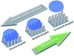
Modulation of droplet mobility on surfaces is crucial in numerous technological applications. Here we present an easy to implement methodology in controlling the mobility of water droplets by means of backpressure application. Tuning the backpressure the inherently sticky hydrophobic porous surface may be readily rendered slippery, reversibly and dynamically with low response time. Gas pockets at the liquid–solid interface are formed and sustained, thus leveraging continuous droplet de-pinning. Thus the surface exhibits slippery macroscopic behavior, without fully developed droplet levitation. Two porous ceramic surfaces are studied: one consisting of sintered primary micro particles exposing randomly distributed micro-posts and a second one shaped by extrusion, part of a honeycomb ceramic structure exhibiting randomly distributed micro-holes. Appropriate vapor deposition was used to render them hydrophobic, exhibiting inherently sticky characteristics. The adequate backpressure to deliver slippery characteristics is experimentally measured for various tilt angles. Ultra-low adequate backpressures of some tens of mbar are reported for the case of the porous surface with the micro-holes, thus providing a rather attractive tool for micro- as well as for large-scale applications. Considering capillary bridging on the in-plane force balance the experimental variations between the two surfaces are explained and correlated to the porous surface microstructure.
1 Introduction
The importance of studying phenomena related to the mobility of droplets on surfaces has rapidly increased recently due to the numerous pertinent technological applications.1–4 The flow in open or closed microfluidics,5–9 the collection of rain drops and fog,10 many chemical processes in droplets,11 self-cleaning technology,12–14 icephobic coatings,15 membrane contactors,16 fuel cells17,18 are only some of the applied areas that call for dynamic, and reversible droplet mobility transitions in order to offer adaptive technical solutions and enhanced performance. Recently a variety of approaches have been proposed towards preparing “active”19 or “tunable”20 or “adaptive”21 surfaces, through which the mobility of droplets is manipulated.
With regard to the droplet mobility, a hydrophobic surface may attain many states from a sticky to multiple slippery states and ultimately the frictionless state. In the first state the droplet pins to the surface and exhibits low mobility, because the liquid fully wets the solid (Wenzel state), as depicted in Fig. 1 for the case of a surface with protruding posts.
 |
| | Fig. 1 Schematic representation of a droplet exhibiting various wetting states, corresponding to different mobility states. As the liquid–solid contact surface area decreases the friction forces are lowered. The surface gradually passes from a sticky to multiple slippery states and finally to a frictionless state. The droplet and the posts are in different length scales. | |
As the liquid–solid contact surface area decreases, the droplet is passing through various Cassie–Baxter states, some of which are also sticky, until a stable state may be reached. In Fig. 1 the droplet rests on top of the posts, exhibiting high mobility (a slippery state). All possible intermediate states are not energetically stable, but may be attained and sustained by an external actuation means, as pressure, electrical power etc. These are also associated with respective variations in mobility. This Wenzel to Cassie–Baxter transition entails overcoming of respective energy barriers,22 and has been realized using various methodologies, including electrowetting and thermal evaporation,23 electrochemical gas production,24 application of over- or under-pressure using a probe from the liquid side.25 Pertinent theory and methodologies have been reviewed recently.26–28 The droplet may move along the surface, upon the exertion of a force, in most cases the gravitational force, through an incline. However, apart from gravitational other forces may also be used to induce movement, such as electrostatic, magnetic, vibrational etc. The aim is to produce surfaces in which the droplet movement is incited with the lower possible adequate effort.29
As the liquid–solid contact surface area decreases more, the other extreme is finally met, in which the droplet is kept completely afloat i.e. there is no contact between the liquid and the solid (Fig. 1). The air cushion under the liquid levitates the droplet and provides a lubrication film ensuring frictionless movement. This air cushion may either be generated by the Leidenfrost phenomenon on hot surfaces,30 or on dry ice,31 or by a stream of air flowing continuously under the droplet.32,33
The existence, preservation, control and regeneration of a continuous or partially developed gas lubrication film at the liquid–solid interface, against pressure, diffusion etc., has proven rather essential towards realizing superhydrophobic and slippery surfaces,34 or controlling the wetting characteristics of droplets after impingement35 even on hydrophilic surfaces.36
In this work we present a generic method for reversible and dynamic mobility transitions on porous surfaces, with low response time. Tuning the backpressure the volume and the pressure of the gas pockets at the liquid–solid interface are controlled. These act as a partially developed gas lubrication film inciting different partial wetting states of the liquid, accompanied by significant variations in the mobility. With appropriate selection of the porous characteristics the surface may switch between the sticky and various slippery states, even with the employment of ultra-low backpressure, i.e. actuation effort.
2 Materials and methods
2.1 Porous surface preparation
To validate our approach two different surfaces will be examined. The first is the surface of a porous disk fabricated from ceramic particles with a size distribution with D0.9 = 7.1 μm uniaxially pressed and sintered, as described in ref. 35 and 37. The second is the open surface of a honeycomb structure. The honeycomb structure was constructed in order to accommodate the backpressure application under the open surface through adjacent channels and was shaped by extrusion of a ceramic paste and sintering. The two surfaces exhibit different microstructure and porosity, as seen in the respective SEM images Fig. 2a and b. The first exhibits protruding particles as randomly distributed posts, while the second randomly distributed holes. However, other inherently sticky porous surfaces may be fabricated e.g. from environmentally friendly materials,38 or materials with tunable micro/nano porosity, structural characteristics, optical and electrical properties.39–41
 |
| | Fig. 2 SEM images and schematics of the experimental setup for the backpressure application. (a) Porous surface of a disk shaped ceramic material fabricated using particles uniaxially pressed and sintered. (b) Porous open surface fabricated by extrusion of a ceramic paste and sintering. In the inset a higher magnification is provided (the bar is 100 nm). | |
The as formed surfaces prior use were heated to 150 °C for 2 h and left to cool down in a desiccator. These structures were then rendered hydrophobic after vapor deposition using a solution precursor of 10% 1H,1H,2H,2H-perfluorododecyltrichlorosilane (PFOTS) (Sigma Aldrich) in cyclohexane, under mild vacuum conditions at 60 °C. After deposition the surfaces were aged in an oven at 130 °C for 24 h. After cool down they were used for the experiments. Static, receding and advancing water contact angles were measured by a GBX-DIGIDROP at ambient atmospheric conditions. The static water contact angle was θ ∼ 125°. The advancing and receding water contact angles were measured on a water droplet of decreasing/increasing volume. The porous surfaces exhibit receding contact angle θr ∼ 110° and advancing contact angle θa ∼ 135°.
2.2 Experimental setup for the backpressure application
The disk shaped specimen was introduced on a Plexiglas holder and an appropriate metal housing under which the gas flow and pressure could be finely controlled with a needle valve (Fig. 2a). The honeycomb structured ceramic was appropriately sectioned and sealed to enable gas feed under the open surface (Fig. 2b). All other open surfaces were sealed to prevent gas leak and tested accordingly. These setups were attached to a tilted stage enabling finely tuned manual rotation. The tilt angle was then measured with accuracy higher than ±2°. The droplet was delivered using micropipette. The backpressure was then increased up to the point until the droplet started to move, as evidenced visually. The backpressure was measured with 2 mbar accuracy, using the KIMO MP 200HP manometer. For each case no less than 5 measurements were conducted, from which an average was extracted. The adequate backpressure error was in all cases less than 5% for the measurements on the surface with the micro-holes. Higher uncertainties, up to 10 mbar were recorded for the surface fabricated using particles uniaxially pressed and sintered.
3 The concept
The concept of our approach is schematically depicted in Fig. 3. A quiescent droplet on a porous surface partially wets the surface due to the existence of the porosity, in which gas pockets are inherently present. Several combinations of porosity morphology and solid surface energy exist in which the intrusion of the liquid in the porous network is not allowable.42 However, in this energetically stable state, the droplet exhibits low mobility; it is impaled to the surface. With the application of backpressure the volume and the pressure of the gas pockets increase, gradually pushing the liquid out of the porous network. In this pressure-mediated state the droplet exhibits higher mobility and the surface slippery characteristics. Transitions between these two states are the core of our study. However, further increase of the backpressure accompanied with increased gas flow leverages a droplet take-off and may render the droplet afloat, in which frictionless movement may be realized. This levitation has been previously thoroughly studied43–45 and demand high gas flow and pressure levels, namely actuation effort, thus hindering application in microsystems.
 |
| | Fig. 3 Schematic illustration of the backpressure application on the droplet. The surface is inherently sticky and the quiescent droplet partially wets the surface. With the application of backpressure gas pockets appear, which incite downhill droplet movement. Farther increase of the backpressure and the gas flow induces a droplet take-off and may sustain a continuous cushion keeping the droplet afloat. The droplet and the posts are in different length scales. | |
Employment of small pressure under the liquid has been exploited before in sustaining slippery surfaces even underwater, by means of electrochemical gas production.24 This case resembles our approach; the difference comes from the source of gas production, being the electrolysis in ref. 24 and external backpressure application in our case.
4 Results and discussion
In Fig. 4 we present experimental results on a porous surface fabricated from particles uniaxially pressed exhibiting D0.9 = 7.1 μm. The experimental data, represent the minimum droplet volume which slides upon the application of a particular backpressure, and inform on the transition of the surface from the sticky to a slippery state. This transition is reversible, dynamic and with low response time.
 |
| | Fig. 4 Effect of the backpressure on the mobility of water droplets of various volumes at porous surfaces from particles at (a) 0°, (b) 20° and (c) 40°. | |
When no backpressure is applied water droplets up to 200 μl remain on the surface at no tilt, namely at tilt ∼ 1° (see Fig. 4a). Maybe larger droplets also stick, but the area of the porous surface constrained us on volumes up to 200 μl. When tilted, the surface sustained droplet of ∼170 μl (Fig. 4b) and 45 μl (Fig. 4c), respectively. The surface demonstrates inherently sticky behavior for volumes up to 200 μl. However this gradually changes with the backpressure application. Tilted at 20° (Fig. 4b) for e.g., the maximum droplet that sticks to the surface falls from 170 μl, to ca. 75 μl and finally to ca. 7 μl, when the backpressure increase to 200 mbar and 510 mbar, respectively.
As the tilt angle increases the slippery states dominate over the sticky state. For e.g. for a 25 μl water droplet at no tilt (i.e. tilt ∼ 1°) a backpressure as-much-as ca. 770 mbar is needed to incite sliding, whereas this decreases to ca. 400 mbar and 180 mbar when the surface is tilted to 20° and 40° respectively.
In Fig. 5 we present the respective experimental data for the porous surface fabricated by extrusion. In this case the pores appear as holes, contrary to the previous case where the particles protrude, as posts. For a virtually horizontal (tilt ∼1°) surface (Fig. 5a) the surface exhibits sticky behavior for droplets up to 70 μl. This maximum droplet volume gradually decreases with tilt angle, from 70 μl to 65 μl, 27 μl and 15 μl under the line connecting the experimental data. Significantly lower backpressure values are needed to render the surface slippery, compared to the surface from particles. The effect of the backpressure and the tilt angle is more intense for droplets with volumes bigger than 15 μl.
 |
| | Fig. 5 Effect of the backpressure on the mobility of water droplets of various volumes at porous surfaces with holes tilted at (a) 0°, (b) 20°, (c) 40°, and (d) 60°. | |
Therefore the critical tilt angle of a droplet, α, is also a function of the backpressure (Pb), and it worth investigating the underline mechanism of this correlation.
In general, the critical tilt angle of a droplet, α, is determined by the governing forces acting on the plane of the surface and takes the following general form:
| |
ρgV sin a = k2ωγ(cos θr − cos θa)
| (1) |
where
ρ and
γ is the density and surface tension of the liquid, respectively,
V the droplet volume, 2
ω is the width of the drop in the direction perpendicular to inclination,
k is a retention-force factor, which is expected to be equal to 1, but is usually adjusted to fit the experimental data.
θr and
θa are the receding and advancing contact angles, respectively, of the droplet on the respective smooth solid surface.
For textured surfaces and in order to account the effect of each capillary bridge on α different approaches have been developed.46–48 In these, additional parameters are introduced, related to the number (n) and the geometrical characteristics of the pillars, as for the case of ref. 49.
| |
 | (2) |
with
L being the length of the pillar on which the droplet pins.
In Fig. 6 the effect of the backpressure is depicted as observed experimentally (left column) and schematically illustrated (right column). Initially the droplet is pinned to the surface, as informed by the measurements in Fig. 4 and 5, but does not penetrate into the porous network. The surface tension (FS = 4Lγ
sin(θr)) in each post exerts a downward force that is opposed by the capillary pressure and the Laplace force
the latter being negligible.48 These forces constitute a pressure balance that is initially in equilibrium, and the droplet is quiescent as in Fig. 6a. The backpressure application is intervened in this pressure balance and gradually provokes detachment of the liquid from the posts.
 |
| | Fig. 6 (Left) Snapshots of the same droplet during backpressure application. (Right) Schematic illustration of the process. (a) Initially the liquid is impaled to the surface. (b) Upon backpressure application the force balance is modified and the liquid is gradually pushed-off, with the gas pockets exhibiting increased volume pressure. In this state the droplet moves downward as may seen in the photo. If the backpressure is farther increased then (c) a plastron gradually develops, the droplet (d) takes-off and then (e) hovers onto the surface. | |
With the application of a backpressure the curvature in each capillary bridge is gradually changed, inciting the formation of multiple gas pockets as seen in Fig. 6b. Of particular interest are the ones resided at the contact line since the droplet pinning stems on those. In Fig. 6b some openings at the front contact line may also be observed. With this scenario the capillary bridges progressively collapse, and n decreases up to the point at which droplet movement is allowable. For example in Fig. 6b the schematic representation demonstrates a decrease of n from 12 to 4. This incites a downhill movement of the droplet as may seen in the sequence of Fig. 6a and b, and this backpressure value is presented in Fig. 4 and 5. Such states are slippery.
Further increase of the backpressure gives rise to the development of a plastron as seen in Fig. 6c and droplet take-off as seen in Fig. 6d. The droplet then hovers onto the surface Fig. 6e. At this particular snapshot the distribution of the gas pockets may be readily seen all over the liquid contact area. We claim however that a complete droplet detachment is not necessary; droplet movement takes place before levitation, thus inquiring mild backpressure conditions in the order of some few mbar as seen in Fig. 5.
In Fig. 7 we present the calculated values of the number of pillars, (n), based on eqn (2), using the experimental results presented in Fig. 4 and in Fig. 5. The solid lines correspond to the mean value of L, being 5 μm and 50 μm for the surface from pressed particles and the extruded, respectively. The dash lines may seen as the uncertainty of n, coming from the extreme variation of L, as informed from the SEM images in Fig. 2. In the left column of Fig. 7 the upper and lower dash line correspond to L = 1 μm and L = 9 μm, respectively. In right column of Fig. 7 the upper and lower dash line correspond to L = 20 μm and L = 70 μm, respectively. Such extreme uncertainties in L, correspond to very large variations in n, which in some cases reach order of magnitude. However some trends with tilt angle and backpressure are systematic and will be discussed hereafter. The corresponding droplet volumes have been added for comparison purposes.
 |
| | Fig. 7 Calculated number of pillars (n) for the two surfaces. (Left) For the surface fabricated from particles the solid lines correspond to L = 5 μm, the extreme upper limit (dash lines) to L = 1 μm and the extreme lower limit (dash line) to L = 9 μm. (Right) For the extruded surface with the holes the solid lines correspond to L = 50 μm, the extreme upper limit (dash lines) to L = 20 μm and the extreme lower limit (dash line) to L = 70 μm. θr = 110° θa = 135°. | |
For e.g. a 50 μl droplet to move on a virtually horizontal (i.e. tilt angle 1°) uniaxially pressed and sintered sample, n shall be ca. 70 based on eqn (2). However, with no backpressure n is much larger and the droplet sticks to the surface. With increasing backpressure n gradually decreases up to the critical value of 70, which is reached at 600 mbar. For the surface with the microholes tilted at 20° and for a 10 μl droplet n is ca. 20. This value is reached only at ca. 30 mbar, after which the surface is macroscopically slippery for this droplet volume.
Significantly smaller number of pillars are calculated for the case of the extruded surface for all tilt angles, comparing the two columns of Fig. 7. This is in concert with the microstructural characteristics seen in the SEM images, and provides a reasoning for the large difference in the adequate backpressure values measured experimentally. In the case of the extruded surface with holes the pillars at which the droplet hinges from, are wider, but much less. On the other hand the uniaxially pressed surface exhibits higher post density, and therefore more capillary bridges may be formed, that shall be collapse in order to allow the droplet movement.
5 Conclusions
We presented a dynamic with low response time, reversible, and easy-to-implement method to render a porous surface from a sticky to a non-sticky, and hence macroscopically slippery state and back. With the application of backpressure the capillary bridges, which act as hinges hindering the droplet movement, are forced to collapse, thus enabling the downward droplet motion. The applicability of our method has been demonstrated in two different surfaces, in terms of their porous microstructure: one fabricated from particles pressed and sintered, exhibiting random micro-posts, and an extruded one exhibiting randomly distributed micro-holes. In the latter case the adequate backpressure to incite the transition from sticky to slippery, is ultra low, in the order of some few tens of mbar, thus providing comparative advantages, compared to the state-of-the art pertinent technologies. The droplet mobility is strongly related to the microstructural surface properties and is well described by the effect of capillary bridging. This provides designing rules for the surface characteristics, that shall be followed in order to attain switching between the sticky and the slippery state, at ultra-low backpressure values.
Acknowledgements
John S. Latsis, Public Benefit Foundation is kindly acknowledged for financial support through the “Research Projects 2015” Grant.
References
- P. G. de Gennes, F. Brochard-Wyart and D. Quere, Capillarity and Wetting Phenomena: Drops, Bubbles, Pearls, Waves, Spinger-Verlag, New York, 2004 Search PubMed.
- D. t Mannetje, S. Ghosh, R. Lagraauw, S. Otten, A. Pit, C. Berendsen, J. Zeegers, D. van den Ende and F. Mugele, Nat. Commun., 2014, 5, 3559 CrossRef PubMed.
- T. S. Wong, S. H. Kang, S. K. Y. Tang, E. J. Smythe, B. D. Hatton, A. Grinthal and J. Aizenberg, Nature, 2011, 477, 443–447 CrossRef CAS PubMed.
- J. D. Smith, R. Dhiman, S. Anand, E. Reza-Garduno, R. E. Cohen, G. H. McKinley and K. K. Varanasi, Soft Matter, 2013, 9, 1772 RSC.
- A. C. Glavan, R. V. Martinez, E. J. Maxwell, A. B. Subramaniam, R. M. Nunes, S. Soh and G. M. Whitesides, Lab Chip, 2013, 13, 2922–2930 RSC.
- D. Moschou, N. Vourdas, G. Kokkoris, G. Papadakis, J. Parthenios, S. Chatzandroulis and A. Tserepi, Sens. Actuators, B, 2014, 199, 470–478 CrossRef CAS PubMed.
- M. Kitsara and J. Ducrée, J. Micromech. Microeng., 2013, 23, 033001 CrossRef.
- N. Vourdas, A. Tserepi, A. Boudouvis and E. Gogolides, Microelectron. Eng., 2008, 85, 1124–1127 CrossRef CAS PubMed.
- E. Gogolides, K. Ellinas and A. Tserepi, Microelectron. Eng., 2015, 132, 135–155 CrossRef CAS PubMed.
- B. S. Lalia, S. Anand, K. K. Varanasi and R. Hashaikeh, Langmuir, 2013, 29, 13081–13088 CrossRef CAS PubMed.
- R. Abdelaziz, D. Disci-Zayed, M. K. Hedayati, J.-H. Pöhls, A. U. Zillohu, B. Erkartal, V. S. K. Chakravadhanula, V. Duppel, L. Kienle and M. Elbahri, Nat. Commun., 2013, 4, 2400 Search PubMed.
- N. Vourdas, A. Tserepi and E. Gogolides, Nanotechnology, 2007, 18, 125304 CrossRef.
- N. E. Vourdas, M. E. Vlachopoulou, A. Tserepi and E. Gogolides, Int. J. Nanotechnol., 2009, 6, 196–207 CrossRef CAS.
- K. Tsougeni, N. Vourdas, A. Tserepi, E. Gogolides and C. Cardinaud, Langmuir, 2009, 25, 11748–11759 CrossRef CAS PubMed.
- A. Davis, Y. H. Yeong, A. Steele, I. S. Bayer and E. Loth, ACS Appl. Mater. Interfaces, 2014, 6, 9272–9279 CAS.
- S. Mosadegh-Sedghi, D. Rodrigue, J. Brisson and M. C. Iliuta, J. Membr. Sci., 2014, 452, 332–353 CrossRef CAS PubMed.
- F. Y. Zhang, X. G. Yang and C. Y. Wang, J. Electrochem. Soc., 2006, 153, A225–A232 CrossRef CAS PubMed.
- J. I. Hur and C.-J. Kim, J. Power Sources, 2015, 274, 916–921 CrossRef CAS PubMed.
- K. S. Khalil, S. R. Mahmoudi, N. Abu-dheir and K. K. Varanasi, Appl. Phys. Lett., 2014, 105, 041604 Search PubMed.
- Y. Zhu, D. S. Antao, R. Xiao and E. N. Wang, Adv. Mater., 2014, 26, 6357 CrossRef CAS PubMed.
- X. Yao, Y. Hu, A. Grinthal, T. S. Wong, L. Mahadevan and J. Aizenberg, Nat. Mater., 2013, 12, 529–534 CrossRef CAS PubMed.
- E. Bormashenko, R. Pogreb, G. Whyman and M. Erlich, Langmuir, 2007, 23, 6501–6503 CrossRef CAS PubMed.
- T. N. Krupenkin, J. A. Taylor, E. N. Wang, P. Kolodner, M. Hodes and T. R. Salamon, Langmuir, 2007, 23, 9128–9133 CrossRef CAS PubMed.
- C. Lee and C.-J. Kim, Phys. Rev. Lett., 2011, 106, 014502 CrossRef.
- T. Verho, J. T. Korhonen, L. Sainiemi, V. Jokinen, C. Bower, K. Franze, S. Franssila, P. Andrew, O. Ikkala and R. H. A. Ras, Proc. Natl. Acad. Sci. U. S. A., 2012, 109, 10210–10213 CrossRef CAS PubMed.
- E. Bormashenko, Adv. Colloid Interface Sci., 2014 DOI:10.1016/j.cis.2014.02.009.
- G. Whyman and E. Bormashenko, J. Adhes. Sci. Technol., 2012, 26, 207–220 CAS.
- M. Reyssat, D. Richard, C. Clanet and D. Quere, Faraday Discuss., 2010, 146, 19–33 RSC.
- E. Bormashenko, R. Pogreb, Y. Bormashenko, R. Grynyov and O. Gendelman, Appl. Phys. Lett., 2014, 104, 171601 CrossRef PubMed.
- D. Quéré, Annu. Rev. Fluid Mech., 2013, 45, 197–215 CrossRef.
- C. Antonini, I. Bernagozzi, S. Jung, D. Poulikakos and M. Marengo, Phys. Rev. Lett., 2013, 111, 014501 CrossRef CAS.
- J. Snoeijer, P. Brunet and J. Eggers, Phys. Rev. E: Stat., Nonlinear, Soft Matter Phys., 2009, 79, 036307 CrossRef.
- J. H. Snoeijer and K. van der Weele, Am. J. Phys., 2014, 82, 1029–1039 CrossRef.
- M. Xu, G. Sun and C.-J. Kim, Phys. Rev. Lett., 2014, 113, 136103 CrossRef.
- N. Vourdas, A. Tserepi and V. N. Stathopoulos, Appl. Phys. Lett., 2013, 103, 111602 CrossRef PubMed.
- J. de Ruiter, R. Lagraauw, D. van den Ende and F. Mugele, Nat. Phys., 2014, 11, 48–53 CrossRef.
- N. Vourdas and V. N. Stathopoulos, Technical Proceedings of the 2014 NSTI Nanotechnology Conference and Expo, NSTI-Nanotech, 2014, p. 2014 Search PubMed.
- A. Milionis, R. Ruffilli and I. S. Bayer, RSC Adv., 2014, 4, 34395–34404 RSC.
- I. Kostis, N. Vourdas, G. Papadimitropoulos, A. Douvas, M. Vasilopoulou, N. Boukos and D. Davazoglou, J. Phys. Chem. C, 2013, 117, 18013–18020 CAS.
- N. Vourdas, K. Dalamagkidis, I. Kostis, M. Vasilopoulou and D. Davazoglou, Opt. Commun., 2012, 285, 5229–5234 CrossRef CAS PubMed.
- N. Vourdas, G. Papadimitropoulos, I. Kostis, M. Vasilopoulou and D. Davazoglou, Thin Solid Films, 2012, 520, 3614–3619 CrossRef CAS PubMed.
- C. W. Extrand and S. I. Moon, Langmuir, 2012, 28, 3503–3509 CrossRef CAS PubMed.
- M. A. Goldshtik, V. M. Khanin and V. G. Ligai, J. Fluid Mech., 1986, 166, 1–20 CrossRef CAS.
- P. Brunet and J. H. Snoeijer, Eur. Phys. J.: Spec. Top., 2011, 192, 207–226 CrossRef.
- W. Bouwhuis, K. G. Winkels, I. R. Peters, P. Brunet, D. van der Meer and J. H. Snoeijer, Phys. Rev. E: Stat., Nonlinear, Soft Matter Phys., 2013, 88, 023017 CrossRef.
- C. W. Extrand and S. I. Moon, Langmuir, 2014, 30, 8791–8797 CrossRef CAS PubMed.
- D. W. Pilat, P. Papadopoulos, D. Schaffel, D. Vollmer, R. Berger and H. J. Butt, Langmuir, 2012, 28, 16812–16820 CrossRef CAS PubMed.
- A. T. Paxson and K. K. Varanasi, Nat. Commun., 2013, 4, 1492 CrossRef PubMed.
- P. Papadopoulos, L. Mammen, X. Deng, D. Vollmer and H.-J. Butt, Proc. Natl. Acad. Sci. U. S. A., 2013, 110, 3254–3258 CrossRef CAS PubMed.
|
| This journal is © The Royal Society of Chemistry 2015 |
Click here to see how this site uses Cookies. View our privacy policy here.