Facile synthesis of silver-decorated reduced graphene oxide as a hybrid filler material for electrically conductive polymer composites

Linxiang He and Sie Chin Tjong*
Department of Physics and Materials Science, City University of Hong Kong, Hong Kong. E-mail: aptjong@cityu.edu.hk; Fax: +852 34420538; Tel: +852 34427702

Received 7th January 2015 , Accepted 23rd January 2015

First published on 23rd January 2015


Abstract

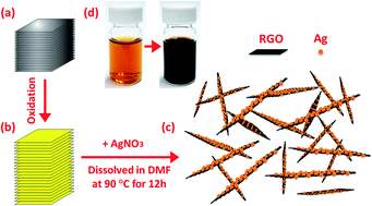
Nano silver-decorated reduced graphene oxide (Ag–RGO) sheets were synthesized by simply dissolving graphite oxide and silver nitrate in N,N-dimethylformamide and keeping the suspension at 90 °C for 12 h. These highly stable hybrid sheets were then incorporated into a polar polymer, polyvinylidene fluoride (PVDF), to prepare the Ag–RGO/PVDF nanocomposites via solution mixing. The Ag–RGO hybrid sheets were dispersed homogeneously in the polymer matrix, resulting in a low percolation threshold of 0.17 vol%. Above the percolation threshold, electrical conductivity of the Ag–RGO/PVDF composite system was about one order of magnitude higher than that of thermally reduced graphene/PVDF composites. This was attributed to the high intrinsic electrical conductivity of silver. The improved electrical properties render this novel composite system an attractive material for antistatic, electrostatic dissipative and electromagnetic/radio frequency interference shielding applications. Furthermore, the resistivity of the composite system increased with increasing temperature, generating a pronounced positive temperature coefficient effect of resistivity.


1. Introduction

Rapid development in electronic industries in recent years leads to an increasing demand for polymeric materials with large electrical conductivity and good flexibility. Conventional polymeric materials are poor electrical conductors that can be rendered conductive by incorporating large contents of metal or carbonaceous microparticles.1–3 However, high filler loadings degrade the flexibility, increase the product weight and cause poor processability.4–9 In this respect, fillers of nanometer dimensions are superior to micromaterials for enhancing the electrical conductivity of polymers.10–12 Carbonaceous nanofillers such as carbon nanotubes (CNTs) possess extraordinarily high mechanical strength and excellent electrical conductivity. They have been widely added to polymers to form electrically conductive polymer composites.13–18 The large aspect ratio of CNTs facilitates the development of a conductive network in the polymer matrix at low filler contents. However, CNTs are still expensive even though their commercial prices have been reduced markedly in recent years.19

In 2004, Geim and co-workers successfully exfoliated graphite into monolayer graphene using the scotch-tape technique.20 Graphene has a large aspect ratio, exceptionally high mechanical strength, superior electrical and thermal conductivity. Thus, it can replace CNTs for reinforcing polymers to form electrically conductive polymer nanocomposites. It has been reported that graphene-based polymer nanocomposites exhibit better electrical and mechanical properties than the CNT/polymer composites.21,22 However, the low production yield of mechanically exfoliated graphene is a major restraint for its applications in polymer nanocomposites. As an alternative, graphene can be prepared by chemically/thermally reducing graphene oxide (GO), which can be synthesized by reacting graphite in strong acid and oxidizing solution. Therefore, chemically/thermally reduced graphene sheets can be mass produced in a facile manner and added to polymers to yield polymer nanocomposites. However, reduced graphene oxide (RGO) sheets exhibit inferior electrical transport properties as compared to pure graphene due to the disruption of the π–π conjugation. This reduces their effectiveness for improving the electrical conductivity of the composites. It has been reported that Ag nanoparticles can decorate RGO to form Ag–RGO hybrid sheets for enhancing the material properties.23 However, Ag–RGO hybrid sheets obtained by glucose reduction were difficult to disperse uniformly in the polymer matrix. This seriously limited their effectiveness for enhancing the electrical properties, and led to a large percolation threshold of 1.52 vol% of the resultant composites.23 In this study, we report a facile synthesis of homogeneous and stable Ag–RGO suspension, and its use as a filler material to fabricate Ag–RGO/polymer composites. The synthesized Ag–RGO hybrid sheets are proved to be more effective in improving the electrical conductivity of polymer composites when compared to RGO sheets. Previously, the utilization of metal nanoparticle-decorated graphene as a hybrid filler material to enhance the electrical properties of polymers is rarely reported in the literature. By combining excellent properties of both graphene and metal nanoparticles, in this work we attempt to exploit the novel applications of this new kind of hybrid sheet in the field of polymer nanocomposites. The polymer material is semicrystalline polyvinylidene fluoride (PVDF) with excellent electroactive properties. It has found wide applications in the electronic and biomedical engineering industries.24

2. Experimental

Graphite flakes and N,N-dimethylformamide (DMF) were purchased from Sigma-Aldrich Inc. (U.S.A.). PVDF (Kynar 500) pellets were provided by Arkema Inc. (U.S.A.). Silver nitrate (AgNO3) was obtained from Beijing Chemical Reagent Co. Graphite oxide was prepared by a typical Hummers method.25 In this study, DMF played a dual role of reducing agent and solvent. It reduced Ag+ ions to Ag atoms26–28 and GO to RGO,29,30 and acted as a good solvent for PVDF.

Fig. 1 illustrated the step procedures of preparing stable Ag–RGO suspension. Firstly, graphite oxide was dissolved in DMF to form a stable GO suspension. Then a predetermined amount of 10 mM AgNO3 aqueous solution was pipetted into the suspension. The suspension was hand-mixed and heated to 90 °C and kept at this temperature for 12 h. During this process, the color of the suspension changed gradually from brown to black, indicating the reduction of GO to RGO. By carefully controlling the temperature and reduction time, the obtained Ag–RGO suspension was homogeneous and very stable, and no dark precipitate formed. To examine the effect of silver decoration on the electrical conductivity of the RGO sheets, Ag–RGO hybrid sheets prepared from different AgNO3/GO mass ratios were compressed into pellets of 0.3 mm thickness for electrical conductivity measurements.


image file: c5ra00257e-f1.tif
Fig. 1 Route for synthesizing Ag–RGO hybrid sheets. (a) Graphite flake, (b) graphite oxide, (c) Ag–RGO sheets obtained by dissolving graphite oxide and AgNO3 in DMF and keeping the solution at 90 °C for 12 h. (d) DMF reduction of Ag+ and GO to Ag–RGO, changing brown color of the suspension to black.

The Ag–RGO hybrid sheets are then regarded as a novel filler material for reinforcing polymers. Its volume fraction can be calculated as follows:

 
image file: c5ra00257e-t1.tif(1)
where p represents the volume fraction of the hybrid fillers; MAg, MRGO and MPVDF are the mass of silver, RGO sheets and PVDF pellets; ρAg = 10.5 g cm−3, ρRGO = 2.25 g cm−3, and ρPVDF = 1.78 g cm−3 are the density of silver, RGO and PVDF, respectively.

To prepare Ag–RGO/PVDF nanocomposite, PVDF pellets were dissolved in DMF at 60 °C. It was then mixed with the Ag–RGO suspension. The mixed suspension was coagulated into a large amount of stirring water.31 The Ag–RGO/PVDF composite mixture precipitated out immediately because of its insolubility in the DMF–water mixture. The obtained fibrous mixture was washed by distilled water and vacuum filtrated. After being dried overnight, the Ag–RGO/PVDF mixture was hot-pressed at 200 °C into sheets of about 0.4 mm thickness.

The Ag–RGO hybrid sheets were examined in a transmission electron microscope (TEM; Philips FEG CM 20). X-Ray diffraction (XRD) patterns of these sheets were recorded on a Philips 220 X'pert diffractometer with Cu Kα radiation (λ = 1.54178 Å). Thermogravimetric analysis (TGA) experiments were carried out on a TA Instruments (TGA Q50) system with the scanning range from 30 °C to 300 °C, and a heating rate of 5 °C min−1 in a nitrogen atmosphere. The morphology of the Ag–RGO/PVDF composites was observed in a field emission scanning electron microscope (FESEM; FEG JSM 6335). Electrical conductivity of the RGO pellet, Ag–RGO pellets and Ag–RGO/PVDF composite were measured with an Agilent 4284A Precision LCR Meter. Prior to the measurements, silver ink was coated on the specimen surfaces to form electrodes. For temperature variation measurements, the specimens were placed inside a computer-controlled temperature chamber. Tensile tests of hot-pressed PVDF and composite specimens were performed at room temperature using an Instron tester at a crosshead speed of 2 mm min−1.

3. Results and discussion

GO contains hydroxyl and epoxide functional groups on their basal planes, as well as carbonyl and carboxyl groups at its sheet edges.32–34 When GO is dispersed in water, these functional groups ionize, making the sheet negatively charged.35 For the system contains metal ions, positively charged metal ions would attach to negatively ionized functional groups of GO through electrostatic attraction. In the presence of a reducing agent, these attached metal ions are converted to metal atoms. At the same time, the reduction of metal ions to metal atoms causes a gradual increase in metal atom concentration, until nucleation becomes energetically favorable. Since heterogeneous nucleation is energetically favored than homogeneous nucleation, metal atoms attached on the GO sheets would trigger the nucleation process. Therefore, the nucleation sites affect the subsequent nanocrystal growth into final metal nanoparticles. This pattern is generally observed for the growth of Au nanoparticles on GO36,37 and Pt nanoparticles on functionalized carbon nanotubes.38 In this study, Ag nanoparticles follow a similar growth mechanism. During the experimental process, we observed only a little amount of isolated Ag nanoparticles, demonstrating that the Ag nucleation occurred primarily on the GO sheets. Besides, we found that the anchored density of Ag nanoparticles can be effectively manipulated. Fig. 2 shows the TEM micrographs of Ag–RGO sheets with different Ag anchored densities. These sheets were obtained by first keeping GO/DMF suspension at 90 °C for different time periods prior to the addition of AgNO3. By keeping the suspension for a longer time, the anchored density of Ag became smaller, implying that the functional groups on GO were partly eliminated by DMF. Therefore, by properly controlling the DMF reduction of GO, Ag–RGO hybrid sheets with desirable Ag anchored density can be obtained.
image file: c5ra00257e-f2.tif
Fig. 2 Ag–RGO hybrid sheets obtained by first keeping GO/DMF suspension at 90 °C for various periods before adding AgNO3: (a) 0 h, (b) 1 h, (c) 3 h and (d) 6 h.

To obtain a stable suspension, the amount of silver anchored on RGO sheets must be carefully controlled. Although more silver decoration resulted in larger electrical conductivity of the Ag–RGO sheets (Fig. 3(a)), dark precipitate usually appeared when the mass ratio of AgNO3 to GO exceeded 1[thin space (1/6-em)]:[thin space (1/6-em)]8. TEM micrographs of the precipitates indicated that these RGO sheets were anchored with large silver nanoparticles (Fig. 3(b)–(d)). This was attributed to long period of heating process needed to fully reduce silver ions, which completely removed functional groups on the RGO sheets and caused aggregation of the formed Ag–RGO sheets. Re-dispersing aggregated RGO or Ag–RGO sheets in polymers were difficult and often led to large percolation threshold,23 thus in this work we confined our study to the Ag–RGO sheets prepared from a 1[thin space (1/6-em)]:[thin space (1/6-em)]8 AgNO3/GO mass ratio.


image file: c5ra00257e-f3.tif
Fig. 3 (a) Electrical conductivity of compressed Ag–RGO pellets prepared from different AgNO3/GO mass ratios. (b, c and d) are TEM micrographs of Ag–RGO hybrid sheets obtained with AgNO3/GO mass ratios of 0.2, 0.5 and 1.

Fig. 4 shows the X-ray diffraction (XRD) patterns of graphite, graphite oxide and Ag–RGO powder. The (002) characteristic peak of graphite oxide (9.7°) locates at a smaller angle than that of graphite (26.75°), implying that the interlayer distance of graphite oxide is expanded due to the formation of oxygen functionalities as illustrated in Fig. 1. These functional groups greatly weaken the van der Waals forces between the layers and therefore facilitate the subsequent exfoliation. For Ag–RGO hybrid sheet, the characteristic peak of graphite oxide disappears and only (111) peak of silver can be observed, implying that the graphite oxide has been almost completely exfoliated. The oxygen functionalities at the GO surface can be effectively removed by thermal heating, leading to a mass loss of GO. Fig. 4(b) shows that GO loses up to 75% of its original mass by heating to 300 °C. In sharp contrast, graphite mass loss is less than 1% when exposed to identical heating conditions. For Ag–RGO sheets, it shows a larger mass loss (5%) than graphite, but the loss is much less than that of GO. This indicates that Ag–RGO sheets still have a certain amount of functional groups. As mentioned before, these functional groups causes the sheets to be negatively charged, thus are responsible for the high stability of Ag–RGO suspension.


image file: c5ra00257e-f4.tif
Fig. 4 (a) XRD patterns of graphite flakes, graphite oxide and Ag–RGO powders. (b) TGA curves of graphite flakes, GO powders and Ag–RGO powders.

Since DMF is a versatile solvent for polymers, thus very stable Ag–RGO suspension renders Ag–RGO a very attractive filler material for the preparation of electrically conductive polymer composites by solution mixing. Fig. 5 shows the SEM images of the prepared Ag–RGO/PVDF composite using the Ag–RGO suspension. The morphology of pure PVDF is provided for comparison. We observe that the incorporation of Ag–RGO hybrid sheets into PVDF changes its morphology markedly. Most of these sheets are crumpled and wrinkled within the polymer, thus interlocked themselves with the PVDF matrix and strengthened the interfacial bonding.


image file: c5ra00257e-f5.tif
Fig. 5 SEM micrographs of (a) pure PVDF and Ag–RGO/PVDF composite at (b) low and (c) high magnification. The filler content is 0.17 vol%.

Fig. 6 shows the DC and AC electrical conductivity of the prepared Ag–RGO/PVDF composites. According to the percolation theory, a rapid increase in the DC electrical conductivity of composite materials takes place when the conductive filler forms an infinite network of connected paths through the insulating matrix. The conductivity of the composite σ(p) above the percolation threshold (pc) is given by:39,40

 
σ(p) = σ0(ppc)t, for p > pc. (2)
where p is the filler content and t the critical exponent. Nonlinear fit in Fig. 6(a) reveals that the percolation occurs when the filler content approaches 0.17 vol%. Such a low pc is evidently due to the large aspect ratio of the Ag–RGO sheets and their homogeneous dispersion in the composites. In principle, randomly oriented oblate ellipsoids (disks) with an aspect ratio of 1000 are predicted to have a geometrical pc of ∼0.1 vol%.41 In our study, the crumpling, wrinkling or folding of the Ag–RGO sheets may decrease their aspect ratio, resulting in a slightly larger pc. Table 1 shows the electrical conductivity of PVDF composites with various types of carbonaceous fillers prepared by solution mixing from this and previous studies.42–45 We find that Ag–RGO/PVDF composite exhibits a smaller pc than almost all other composites. Although Ag–RGO/PVDF composite system has a pc slightly larger than in situ formed thermally reduced graphene (TRG) based PVDF composite,42 above pc its conductivity is almost one order of magnitude larger than that of TRG/PVDF composite. When no silver is anchored on the RGO sheets, electrical conductivity of the composite is much smaller (Fig. 6(a)). Generally, electrical conductivity of the conductive polymer composites is governed by two factors: intrinsic conductivity of the filler material and contact resistance between the fillers. Since silver has an electrical conductivity (6.30 × 10⁵ S cm−1) three times order of magnitude larger than that of even highly conductive RGO (2.02 × 10² S cm−1),46 its anchoring on RGO can improve the electrical transport properties within the Ag–RGO fillers. In addition, as an excellent electrical conductor, silver has been widely used as the electrode material to ensure good electrical contact. Its decoration on RGO is thus expected to reduce the contact resistance between the RGO sheets. This greatly facilitates the flow of charge carriers across the contact regions between the fillers, thus enhancing the electrical conduction behavior of the resultant composite.


image file: c5ra00257e-f6.tif
Fig. 6 (a) Static electrical conductivity of Ag–RGO/PVDF composites as a function of filler content. Main figure: composite conductivity, σ, versus filler volume fraction, p. Right inset: electrical conductivity of compressed Ag–RGO, TRG and RGO pellets. The black solid line gives the calculated conductivity based on the fitting of numerical data to eqn (2). Fitted parameters are: pc = 0.17 ± 0.02 vol%, t = 2.15 ± 0.20 and σ0 = 1120.40 ± 152.45 S cm−1. The red and blue dash lines give the electrical conductivities of TRG/PVDF composite,42 and RGO/PVDF composite, respectively. (b) AC electrical conductivity of Ag–RGO/PVDF composites.
Table 1 Electrical conductivity of PVDF nanocomposites with carbonaceous fillers prepared by solution mixinga
Filler pc, vol% σ, S cm−1 Ref.
a MWNT: Multi-walled carbon nanotube; CNF: carbon nanofiber; GNP: graphite nanoplatelet; EG: expanded graphite.
Ag–RGO 0.17 vol% 3.8 × 10⁻² at 1 vol% This work
TRG 0.12 vol% 6.4 × 10⁻³ at 1 vol% 42
MWNT 0.98 vol% 5.97 × 10⁻⁵ at 1.5 vol% 43
CNF 1.46 vol% 1.51 × 10⁻⁴ at 2.5 vol% 43
GNP 2.4 wt% 8.09 × 10⁻⁴ at 3 wt% 44
EG 6 vol% 7.2 × 10⁻⁴ at 8 vol% 45


The AC electrical conductivity of conductor/insulator composite materials provides useful information about the arrangement of the internal conducting clusters. The DC electrical conductivity plateau usually implies the formation of a well-percolated conductive network. At 0.12 vol% filler loading, the electrical conductivity increases almost linearly with frequency, indicating that the isolated conducting clusters have not linked together to form a network. By slightly increasing the loading level to 0.17 vol%, however, the conductivity shows a marked increase in low-frequency regime with the appearance of a DC plateau. The appearance of DC plateau reveals the formation of a conducting network within the system, conforming to the static electrical conductivity measurement. Further increase in filler loading raises the DC plateau as a result of the formation of a well-developed, percolating Ag–RGO network.

The increased electrical conductivity of percolated Ag–RGO/PVDF composite provides it with antistatic or electrostatic dissipative (ESD) or electromagnetic/radio frequency interference (EMI/RFI) shielding or a combination of these properties. Fig. 7 shows the surface resistivity of Ag–RGO/PVDF films with different thicknesses as a function of Ag–RGO content. At a filler loading of 0.17 vol%, the conductivity of the composite film already satisfies the antistatic and ESD criteria.47,48 An increase in Ag–RGO loading to 1 vol% gives a resistance in the order of 104 Ω sq.−1, which already fulfills the requirement of EMI/RFI shielding applications.47,48


image file: c5ra00257e-f7.tif
Fig. 7 Equivalent surface resistivity of the Ag–RGO/PVDF films of different thicknesses as a function of filler volume fraction.

The effect of temperature on resistivity of Ag–RGO/PVDF composite was evaluated in the temperature range of 40–170 °C. Fig. 8 shows that the composites exhibit an increase in resistivity with increasing temperature. This is followed by a sharp increase in resistivity, when the melting point of PVDF is reached. The resistivity varies by more than two orders of magnitude when the temperature increases from 40 °C to 170 °C, resulting in the so-called positive temperature coefficient (PTC) effect of resistivity.


image file: c5ra00257e-f8.tif
Fig. 8 Effect of temperature on resistivity of Ag–RGO/PVDF composites with 0.17 vol% and 0.24 vol% filler loadings.

At a low filler content, the Ag–RGO sheets cannot form a conducting network in the insulating polymer matrix. As a result, the electrical conduction occurs based on the “Zener tunneling or internal field emission effect”.49–52 As the number of electrical contacts increases because of an increase in the filler content, the Ag–RGO sheets can contact each other to form a conducting network throughout the system, resulting in a high conductivity of the composite. An increase in temperature can disrupt the conducting network, thus increase the electrical resistivity. The maximum increase in resistivity is seen for the composite with 0.17 vol% Ag–RGO, with almost three orders of magnitude change in resistivity (Fig. 7). The increase in resistivity is found to be reversible only for a certain temperature range. Above the melting temperature of PVDF, the PTC effect became irreversible, implying that the arrangements of conducting clusters and/or network within the system can not be recovered. Materials exhibit a pronounced PTC effect can find applications in various fields like sensors, self-regulating or overcurrent protection material.53,54 The PTC behavior of the Ag–RGO/PVDF composite enables the material to respond rapidly to the temperature change, making it attractive for a variety of smart device applications.

The mechanical properties of polymer nanocomposites are crucial for their practical applications. Fig. 9(a) shows the stress–strain plots of Ag–RGO/PVDF composites while the tensile properties vs. Ag–RGO content are depicted in Fig. 9(b). It is apparent that the tensile strength of the composites increases with increasing Ag–RGO content, demonstrating that these fillers reinforce PVDF effectively. However, the strain at break decreases with an increase in the Ag–RGO content. This is due to the weaker interactions between the fillers and PVDF matrix, which restrict the movements of polymer chains. This behavior is a typical behavior of polymer composites reinforced with fillers of nanoscale dimension.55–57


image file: c5ra00257e-f9.tif
Fig. 9 (a) Stress–strain curves of Ag–RGO/PVDF nanocomposite sheets with different Ag–RGO contents. (b) Tensile strength (left) and tensile strain (right) versus Ag–RGO loading content.

4. Conclusions

Ag–RGO hybrid sheets were synthesized by simply dissolving graphite oxide and silver nitrate in DMF and keeping the suspension at 90 °C for 12 h. The obtained sheets were then used to improve the electrical properties of PVDF. Furthermore, these sheets were dispersed homogeneously in the polymer matrix, resulting in a low percolation threshold of 0.17 vol%. Comparing with TRG/PVDF composites, the Ag–RGO/PVDF composite system showed improved electrical conduction behavior. This was attributed to high intrinsic electrical conductivity of silver. The improved electrical properties render such novel composite system a potential material for antistatic and ESD and EMI/RFI shielding applications. Finally, the resistivity of the composite increased with increasing temperature, yielding a pronounced PTC effect of resistivity, making it attractive for a variety of smart device applications.

Acknowledgements

This work is supported by the project (R-IND4401), Shenzhen Research Institute, City University of Hong Kong.

References

  1. G. C. Psarras, Composites, Part A, 2006, 37, 1545–1553 CrossRef PubMed.
  2. R. A. Mrozek, P. J. Cole, L. A. Mondy, R. R. Rao, L. F. Bieg and J. L. Lenhar, Polymer, 2010, 51, 2954–2958 CrossRef CAS PubMed.
  3. Y. Z. Meng, A. S. Hay, X. G. Jian and S. C. Tjong, J. Appl. Polym. Sci., 1998, 68, 137–143 CrossRef CAS.
  4. S. C. Tjong, S. L. Liu and R. K. Y. Li, J. Mater. Sci., 1996, 31, 479–484 CrossRef CAS.
  5. Y. Z. Meng and S. C. Tjong, Polymer, 1998, 39, 99–107 CrossRef CAS.
  6. S. C. Tjong and Y. Z. Meng, Polymer, 1997, 38, 4609–4615 CrossRef CAS.
  7. J. Z. Liang, R. K. Y. Li and S. C. Tjong, Polym. Compos., 1999, 20, 413–422 CrossRef CAS.
  8. K. L. Fung, R. K. Y. Li and S. C. Tjong, J. Appl. Polym. Sci., 2002, 85, 169–176 CrossRef CAS.
  9. X. H. Li, S. C. Tjong, Y. Z. Meng and Q. Zhu, J. Polym. Sci., Part B: Polym. Phys., 2003, 41, 1806–1813 CrossRef CAS.
  10. L. X. He and S. C. Tjong, Nanoscale Res. Lett., 2013, 8, 132 CrossRef PubMed.
  11. J. Song and J. Jang, RSC Adv., 2013, 3, 22308–22313 RSC.
  12. S. P. Bao, G. D. Liang and S. C. Tjong, Carbon, 2011, 49, 1758–1768 CrossRef CAS PubMed.
  13. B. Biswas, A. Chowdhury and B. Mallik, RSC Adv., 2013, 3, 3325–3332 RSC.
  14. R. Xu and X. Xu, RSC Adv., 2014, 4, 42226–42233 RSC.
  15. S. Maiti, S. Suin, N. K. Shrivastava and B. B. Khatua, RSC Adv., 2014, 4, 7979–7990 RSC.
  16. L. X. He and S. C. Tjong, Eur. Phys. J. E, 2010, 32, 249–254 CrossRef CAS PubMed.
  17. L. X. He and S. C. Tjong, J. Nanosci. Nanotechnol., 2011, 11, 3916–3921 CrossRef CAS PubMed.
  18. L. X. He and S. C. Tjong, J. Nanosci. Nanotechnol., 2011, 11, 10668–10672 CrossRef CAS PubMed.
  19. http://www.nanoamor.com.
  20. K. S. Novoselov, A. K. Geim, S. V. Morozov, D. Jiang, Y. Zhang, S. V. Dubonos, I. V. Grigorieva and A. A. Firsov, Science, 2004, 306, 666–669 CrossRef CAS PubMed.
  21. T. Kuilla, S. Bhadrab, D. Yao, N. H. Kim, S. Bose and J. H. Lee, Prog. Polym. Sci., 2010, 35, 1350–1375 CrossRef CAS PubMed.
  22. S. Stankovich, D. A. Dikin, G. H. Dommett, K. M. Kohlhaas, E. J. Zimney, E. A. Stach, R. D. Piner, S. T. Nguyen and R. S. Ruoff, Nature, 2006, 442, 282–285 CrossRef CAS PubMed.
  23. S. Wageh, L. X. He, A. A. Al-Ghamdi, Y. A. Al-Turkid and S. C. Tjong, RSC Adv., 2014, 4, 28426–28431 RSC.
  24. H. S. Nalwa, Ferroelectric Polymers: Chemistry, Physics and Applications, Marcel Dekker, New York, 1995 Search PubMed.
  25. W. S. Hummers and R. E. Offeman, J. Am. Chem. Soc., 1958, 80, 1339 CrossRef CAS.
  26. I. Pastoriza-Santos and L. M. Liz-Marzán, Adv. Funct. Mater., 2009, 19, 679–688 CrossRef CAS.
  27. I. Pastoriza-Santos and L. M. Liz-Marzán, Langmuir, 1999, 15, 948–951 CrossRef CAS.
  28. I. Pastoriza-Santos and L. M. Liz-Marzán, Pure Appl. Chem., 2000, 72, 83–90 CrossRef CAS.
  29. O. C. Compton, B. Jain, D. A. Dikin, A. Abouimrane, K. Amine and S. T. Nguyen, ACS Nano, 2011, 5, 4380–4391 CrossRef CAS PubMed.
  30. K. Ai, Y. Liu, L. Lu, X. Cheng and L. Huo, J. Mater. Chem., 2011, 21, 3365–3370 RSC.
  31. F. M. Du, J. E. Fischer and K. I. Winey, J. Polym. Sci., 2003, 41, 3333–3338 CrossRef CAS.
  32. C. Hontoria-Lucas, A. J. López-Peinado, J. d. D. López-González, M. L. Rojas-Cervantes and R. M. Martín-Aranda, Carbon, 1995, 33, 1585–1592 CrossRef CAS.
  33. H. Hea, J. Klinowskia, M. Forsterb and A. Lerfb, Chem. Phys. Lett., 1998, 287, 53–56 CrossRef.
  34. A. Lerf, H. He, M. Forster and J. Klinowski, J. Phys. Chem. B, 1998, 102, 4477–4482 CrossRef CAS.
  35. D. Li, M. B. Müller, S. Gilje, R. B. Kaner and G. G. Wallace, Nat. Nanotechnol., 2008, 3, 101–105 CrossRef CAS PubMed.
  36. G. Goncalves, P. A. A. P. Marques, C. M. Granadeiro, H. I. S. Nogueira, M. K. Singh and J. Grácio, Chem. Mater., 2009, 21, 4796–4802 CrossRef CAS.
  37. K. Jasuja and V. Berry, ACS Nano, 2009, 3, 2358–2366 CrossRef CAS PubMed.
  38. S. L. Knupp, W. Li, O. Paschos, T. M. Murray, J. Snyder and P. Haldar, Carbon, 2008, 46, 1276–1284 CrossRef CAS PubMed.
  39. C. W. Nan, Y. Shen and J. Ma, Annu. Rev. Mater. Res., 2010, 40, 131–151 CrossRef CAS.
  40. C. W. Nan, Prog. Mater. Sci., 1993, 37, 1–116 CrossRef CAS.
  41. E. J. Garboczi, K. A. Snyder, J. F. Douglas and M. F. Thorpe, Phys. Rev. E: Stat. Phys., Plasmas, Fluids, Relat. Interdiscip. Top., 1995, 52, 819–828 CrossRef CAS.
  42. L. X. He and S. C. Tjong, RSC Adv., 2013, 3, 22981–22987 RSC.
  43. L. X. He and S. C. Tjong, Curr. Nanosci., 2010, 6, 520–524 CrossRef CAS.
  44. Y. C. Li, S. C. Tjong and R. K. Y. Li, Synth. Met., 2010, 160, 1912–1919 CrossRef CAS PubMed.
  45. Y. C. Li, R. K. Y. Li and S. C. Tjong, J. Nanomater., 2010, 261748 Search PubMed.
  46. W. Gao, L. B. Alemany, L. Ci and P. M. Ajayan, Nat. Chem., 2009, 1, 403–408 CrossRef CAS PubMed.
  47. J. Markarian, Plast. Addit. Compd., 2005, 26–30 CrossRef.
  48. J. Amarasekera, Reinf. Plast., 2005, 38–41 CrossRef.
  49. L. X. He and S. C. Tjong, Synth. Met., 2010, 160, 2085–2088 CrossRef CAS PubMed.
  50. L. X. He and S. C. Tjong, Synth. Met., 2011, 161, 540–543 CrossRef CAS PubMed.
  51. L. X. He and S. C. Tjong, Synth. Met., 2012, 161, 2647–2650 CrossRef PubMed.
  52. L. X. He and S. C. Tjong, eXPRESS Polym. Lett., 2013, 7, 375–382 CrossRef CAS.
  53. S. Isaji, Y. Z. Bin and M. Matsuo, Polymer, 2009, 50, 1046–1053 CrossRef CAS PubMed.
  54. D. Azulay, M. Eylon, O. Eshkenazi, D. Toker, M. Balberg, N. Shimoni, O. Millo and I. Balberg, Phys. Rev. Lett., 2003, 90, 236601 CrossRef CAS.
  55. G. D. Liang, S. P. Bao and S. C. Tjong, Mater. Sci. Eng., B, 2007, 142, 55–61 CrossRef CAS PubMed.
  56. S. C. Tjong and Y. Z. Meng, J. Polym. Sci., Part B: Polym. Phys., 2003, 41, 2332–2341 CrossRef CAS.
  57. S. C. Tjong and S. P. Bao, Compos. Sci. Technol., 2007, 67, 314–323 CrossRef CAS PubMed.

This journal is © The Royal Society of Chemistry 2015
Click here to see how this site uses Cookies. View our privacy policy here.