
Fabrication of ordered arrays of CNT/TiO2 nanotubes and their photocatalytic properties†
Xiaofei Qua,
Lixin Caob and
Fanglin Du*a
aCollege of Materials Science and Engineering, Qingdao University of Science and Technology, Qingdao, 266042, Shandong Province, P. R. China. E-mail: dufanglin2008@hotmail.com; Tel: +86-532-84022870
bCollege of Chemistry and Chemical Engineering, Ocean University of China, Qingdao 266100, Shandong Province, P. R. China
First published on 17th February 2015
Abstract
In this work, fabrication and characterization of ordered arrays of CNT/TiO2 nanotubes imbedded in porous anodic aluminum oxide (AAO) membranes were reported. The coaxial core–shell structures were exploited for the photocatalytic degradation of organic pollutants, such as methyl orange. The presence of the CNT greatly enhanced the efficiency of photocatalytic activity compared with the bare TiO2 nanotubes. The key achievement of this work is to fabricate ordered arrays of CNT/TiO2 composite nanotubes with coaxial core–shell structures by using a simple, convenient, and environmentally friendly process. Further application of this CNT/TiO2 hybrid material in many fields could be hopefully expected.
In recent years, there has been increasing interest in TiO2 because of its biological and chemical inertness, excellent stability and non-toxicity.1 Although catalysts in the form of nanoparticles show a good activity due to their large surface-to-volume ratios, separation of these powdered photocatalysts from suspended solution could be very difficult for the purpose of recycled usage. Another limitation encountered with TiO2 is that due to its wide band gap of ∼3.2 eV, it only absorbs light with wavelengths of ∼387 nm and below, which significantly diminishes the utilization of solar energy. In addition, most applications of TiO2 still suffer from the easy recombination of photogenerated electron–hole pairs.
Compared with nanoparticles or bulk materials, the photocatalysts in the form of nanotube arrays own many advantages including facilitation of recycle usage and higher photocatalytic activity derived from long-distance electron transport and larger specific surface area.2,3 As for the limitation of light absorption and easy recombination of the photogenerated electron–hole pairs which TiO2 suffers from, the idea coupling TiO2 with CNT has been popular. For CNTs, owing to their large surface-to-volume ratio, good mechanical behavior and excellent properties of transporting or shuttling electrons,4 they have been extensively combined with TiO2 to overcome TiO2's limitations. Up to now, various approaches including hydrothermal process,5 sol–gel method,6 and electrochemically coating method7 have been exploited in the synthesis of CNT/TiO2 composites and the composites CNT/TiO2 have been investigated in many fields, such as photo-catalysis,8 solar cell,9 lithium storage,10 and so on.
The conventional techniques preparing CNT/TiO2 composites usually have some disadvantages. For example, the CNTs need to be treated with strong acids to introduce active function groups on their surface;11 some organic stabilizers are introduced in order to prevent nanoparticles from agglomerating.12,13 In addition, most of these methods only concern about loading TiO2 particles on the outer wall of randomly dispersed CNTs.14,15 To our knowledge, there is only one paper about loading TiO2 in the inner wall of CNT and it is reported that a high photoactivity under visible-light irradiation could be obtained for the structure TiO2 confinement inside CNT.8
Here, we report a simple and effective route to prepare well-ordered CNT/TiO2 nanotube arrays with the assistance of AAO membranes as templates. AAO membrane contains lots of ordered nanochannels, which makes it a suitable template for the fabrication of one-dimensional nano-structures. As for the CNT/TiO2 composites, some other approaches to fabricate TiO2 nanotubes require the use of a metallic Ti substrate to support the TiO2 nanotube array,16 but the process to remove the Ti substrate and barrier layer is complex and involves the use of hydrogen fluoride which may be harmful for the environment.17 In this work, CNT/TiO2 composite core–shell coaxial nanotube arrays were fabricated by chemical vapor deposition (CVD) and hydrolytic reaction using AAO membranes as the templates and our work has following highlights:
(1) Compared to the forms of nanoparticles or other bulk materials, the product in the form of nanotube arrays is easier to be recycled, avoiding secondary pollution.
(2) A new structure was obtained in our work. TiO2 nanotubes are assembled on the inwall of ordered CNT arrays while many studies are mainly focusing on loading TiO2 on the outer wall of randomly dispersed CNT.
(3) The method to fabricate CNT/TiO2 core–shell coaxial nanotube arrays is environmentally friendly with no strong acids or alkali during the process.
In a typical process, the carbon nanotubes were firstly deposited on the entire surface of the AAO membrane by using a chemical vapor deposition (CVD) method, and then TiO2 was deposited on the inner surface of the AAO/CNT via hydrolysis of titanium isopropoxide. Further experimental details are provided in the ESI.†
The morphologies of the prepared samples were examined by SEM and TEM tests. For CNTs, the hollow feature could be seen from the tips of the nanotubes in Fig. S1a (ESI†). The obtained CNTs kept a good orientation and parallel with each other. The outside diameter of these nanotubes was equivalent to the pore diameter (200–300 nm) of the AAO template, and the length of these nanotubes was equal to the thickness of the employed AAO membrane (∼50 μm) (the inset of Fig. S1a†). Fig. S1b† showed the TiO2 nanotubes were arranged roughly parallel to one another, and were highly uniform in diameter, which indicated that the ordered TiO2 nanotubes could be successfully constructed in nanochannels of AAO using hydrolysis of titanium isopropoxide with the help of sonication operation. For CNT/TiO2, the feature of the core–shell structure was clear in the broken section from Fig. S1c† (indicated by circles). It could be seen that some TiO2 nanoparticles appeared in the broken part for the composite nanotubes. Here the energy dispersive spectroscopy (EDS) data corresponding to the samples were also shown in the right parts of Fig. S1.† The peaks of Ti, O, and C could be clearly seen, indicating that the TiO2 nanotubes, CNTs and CNT/TiO2 composite nanotubes could be obtained in our work. The element of Na could be introduced by the operation of dissolving the AAO template using NaOH solution. The Si signal originated from the silicon wafer, which was used as the substrate to hold the samples. The additional reflection of Pt in the EDS spectra were due to Pt coating convenient for the SEM measurements.
Further evidence for the core–shell structure could be found from the transmission electron microscopy (TEM) image shown in Fig. 1. Fig. 1a and b were the TEM images of the carbon nanotube and TiO2 nanotube, respectively, showing that the wall thickness of CNT and TiO2 nanotube was both about 10 nm. In addition, a typical TEM image of CNT/TiO2 composite nanotube was shown in Fig. 1c. The distinct interface between the outer layer of CNT and the inner layer of TiO2 suggested the structure of core–shell coaxial nanotube heterojunctions were obtained by our method. The structures of the prepared nanotubes were determined by selected area electron diffraction (SAED) studies. It clearly showed that CNT/TiO2 composite nanotube was composed of anatase-type TiO2 structure with four diffraction rings corresponding to the (101), (004), (200), and (211) planes and graphitic multiwalled CNT structure with typical (100) and (004) planes (inset of Fig. 1c).18,19 Based on the analysis of SEM and TEM, it could be concluded that the average outer diameter of the prepared nanotubes was 200–300 nm and the length was up to 50 μm, which perfectly corresponded to the size of the AAO template. HRTEM may offer further insight into the morphology and microstructure of CNT/TiO2 composites, as shown in Fig. 1d. The lattice fringes with spacing of 0.35 nm were in good agreement with the characteristic of anatase TiO2.
 | ||
| Fig. 1 TEM and SAED analyses of (a) CNTs, (b) TiO2 nanotubes (c) CNT/TiO2 nanotubes. (d) High-resolution TEM image of CNT/TiO2 nanotubes. | ||
XPS technique was further used to investigate the chemical composition of the samples. Fig. 2a was the whole scanning spectrum of the sample TiO2 and CNT/TiO2, including C, Ti and O. Fig. 2b showed the high-resolution spectra of the C 1s. For CNT/TiO2, the peak at 286.4 eV attributed to Ti–O–C bond.20 The other peaks for CNT/TiO2 (284.6 eV, 290.2 eV) and for TiO2 (284.8 eV, 288.7 eV) were assigned to C–C bond and COO bond.21 The existence of these polar groups may indicate that the surface of the CNT was oxidized to some extent, which may be helpful for the absorption of the precursor molecules and/or the nucleation of the TiO2 on the surface of CNTs.22 The two peaks for TiO2 at about 458.6 eV and 464.2 eV and for CNT/TiO2 at 458.8 eV and 464.5 eV in Fig. 2c could be assigned to the levels of Ti4+ 2p3/2 and Ti4+ 2p1/2, respectively.23 The additional two peaks for CNT/TiO2 composite at 457.7 eV and 463.1 eV corresponded to Ti3+ 2p1/2 and Ti3+ 2p3/2, respectively, suggesting the presence of the Ti3+ species.24 Ti3+ could be regarded as a surface defects on the surface of TiO2 (Ti4+). It was reported that the increased Ti3+ could not only increase oxygen adsorption and, then photooxidation25 but also inhibit the photogenerated electrons–holes recombination.26 Therefore, the existence of the Ti3+ species in the CNT/TiO2 composite may be responsible for its enhanced photocatalytic property. As shown in Fig. 2d, the peak of O 1s located at 532.5 eV for CNT/TiO2 could be identified, corresponding to H2O molecules chemisorbed on the sample surface.24 The peak at 530.4 eV for CNT/TiO2 and 530.0 eV for TiO2 could be assigned to the binding energy of Ti–O.20 The peak at 531.7 eV for TiO2 corresponded to Ti–OH.27
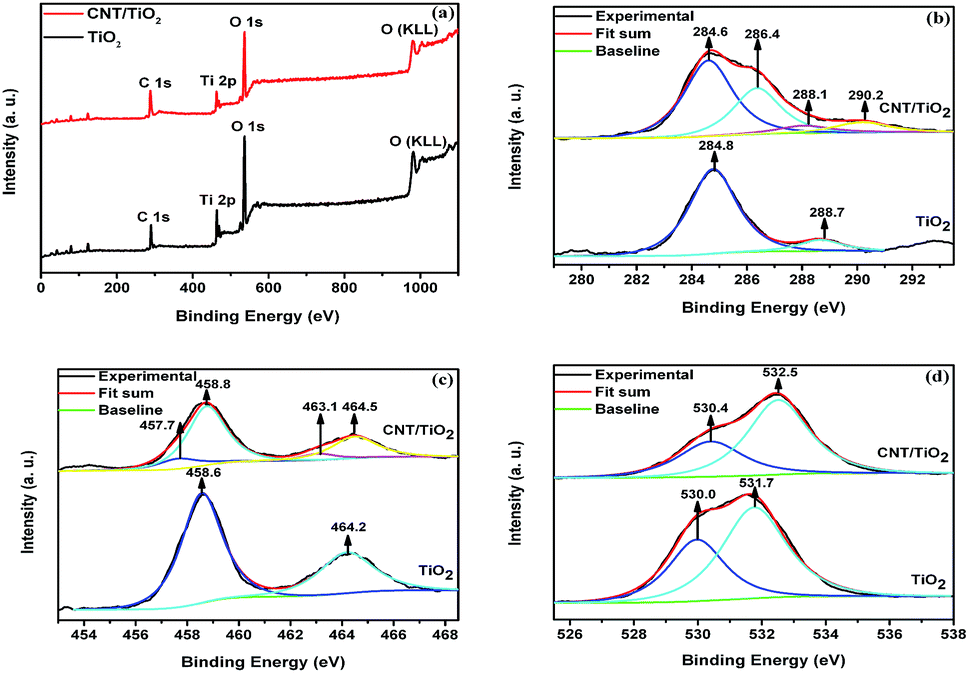 | ||
| Fig. 2 (a) XPS whole scanning spectrum of TiO2 and CNT/TiO2; (b–d) high-resolution XPS spectra of C, Ti and O in TiO2 and CNT/TiO2. | ||
N2 adsorption–desorption isotherms of the samples CNT, TiO2 and CNT/TiO2 core–shell coaxial structures were also measured (Fig. S2†). It was shown that all the samples exhibited type-IV isotherms.28 The BET surface areas of the prepared catalysts were listed in Table 1 (ESI†). The CNT/TiO2 composite catalysts exhibited much higher surface areas than the bare TiO2 nanotube catalyst. A large specific surface area could benefit the absorption of the target pollutant, which was crucial during the photocatalytic activities. For CNT/TiO2 composite nanotubes, because of the higher surface area, it may own better photocatalytic activity than that of bare TiO2 nanotubes.
The light absorption of the samples TiO2 nanotubes, CNTs, and CNT/TiO2 composite nanotubes were characterized using UV-vis diffuse reflectance spectra (Fig. S3†). The absorption threshold of TiO2 was about 387 nm, corresponding to the band gap of anatase (∼3.2 eV),29 while CNT absorption covered the whole range of the measured UV-vis region. For CNT/TiO2, it could be seen that the introduction of the carbon into TiO2 led to an increasement of light absorption in the visible spectral region, which was consistent with the reported paper.30
For the samples, the comparison about the photocatalytic activities was shown in Fig. 3. The kinetics of the degradation reaction were fitted to a pseudo-first-order rate using the equation ln(C0/C) = κt, where κ was the apparent rate constant and t was the irradiation time. The following κ data for TiO2 nanotube, CNTs and TiO2/CNTs composite nanotubes was 0.0080, 0.0035 and 0.0143 min−1, respectively (see Table 2 in ESI†). It was clear that the CNT/TiO2 composite nanotube arrays owned better photocatalytic activity than that of TiO2 nanotubes and CNTs.
 | ||
| Fig. 3 Linear transform ln(C0/C) = f(t) of the kinetic curves of MO degradation of (a) an empty AAO template, (b) CNTs imbedded in an AAO template, (c) TiO2 nanotubes imbedded in an AAO template, and (d) CNT/TiO2 composite nanotubes imbedded in an AAO template. | ||
As a photocatalyst, the activity is greatly affected by many factors, such as crystal structure, catalyst's surface, size distribution, band gap and so on. In our work, one reason for the higher photocatalystic activity of the CNT/TiO2 coaxial core–shell nanostructure may be the higher carrier mobility and less recombination of photogenerated electrons and holes resulting from the coupling of CNTs. When the CNT/TiO2 photocatalyst was illuminated under UV light, electrons in TiO2 were excited from valence band (VB) into conduction band (CB), leaving highly oxidative holes in VB and forming negative sites in CB. Some photogenerated electrons could recombine with holes, which led to the decrease of photocatalytic efficiency. Some were quickly conveyed to the CNTs because of the strong interactive force between two materials CNT and TiO2 and the large electron storage capacity of CNT.31 Because the photogenerated electrons quickly moved to the CNT while holes were left behind in TiO2, separation of the e−–h+ pairs could be created and the recombination of e−–h+ could be reduced. Thus, the integration of nanotubular TiO2 and CNT in a proper fashion could combine advantages of them and the enhanced photocatalytic performance could be obtained for CNT/TiO2 composite nanotubes in comparison with the bare TiO2 bulk materials or nanoparticles.
In addition, due to the large specific surface area of CNT/TiO2, it may have enhanced adsorption capacity and exhibit superior photocatalytic performance compared with that of bare TiO2. Adsorption is a key process in the photocatalytic destruction of pollutants.32 The last but not the least, Ti3+ could be regarded as a surface defects on the surface of TiO2 (Ti4+). The existence of the Ti3+ species in the CNT/TiO2 composite may be helpful for the photocatalytic activity.
Based on several factors above, CNT/TiO2 owned enhanced photocatalytic properties compared with bare TiO2 nanotube arrays.
Conclusions
In conclusion, a new method for preparing ordered coaxial core–shell CNT/TiO2 nanotube arrays with heterojunction structures by using AAO template was proposed. The length of the coaxial CNT/TiO2 core–shell nanotubes was 50 μm, which was the same as the thickness of the AAO membranes. The heterojunction nanotubes were much longer than those obtained from methods using dispersed CNTs. The wall thickness of the core–shell nanotubes was uniform. The fabrication process is simple, convenient, and is suitable for application over large areas of the AAO membranes to produce large size and well ordered core–shell heterojunction arrays.The CNT/TiO2 core–shell nanotube arrays exhibited higher photocatalytic activity in comparison to the bare TiO2 nanotubes:
(1) Compared with bare TiO2 nanotubes, CNT/TiO2 composite nanotubes exhibited enhanced sunlight absorption in the visible region.
(2) CNT/TiO2 composite nanotube arrays owned larger specific surface area than that of bare TiO2 arrays.
(3) After coupling with CNTs, Ti3+ was confirmed to be existed in the CNT/TiO2 composite core–shell coaxial nanotubes, which may be responsible for its superior photocatalytic performance.
Furthermore, the noble metals, which could act as electron traps, such as Pt, Au, or other active materials, have been considered to enhance the catalytic activity of the CNT/TiO2 photocatalyst and the relative investigation will soon be presented in future report.
Acknowledgements
This work was financially supported by National Natural Science Foundation of China (Grant no. 51272115) and The Scientific Research Encouragement Foundation for Outstanding Young and Middle Aged Scientists of Shandong Province, China (Grant no. BS2013CL025).Notes and references
- M. R. Hoffmann, S. T. Martin, W. Choi and D. W. Bahnemann, Chem. Rev., 1995, 95, 69–96 CrossRef CAS.
- J. R. Jennings, A. Ghicov, L. M. Peter, P. Schmuki and A. B. Walker, J. Am. Chem. Soc., 2008, 130, 13364–13372 CrossRef CAS PubMed.
- T. Tachikawa and T. Majima, J. Am. Chem. Soc., 2009, 131, 8485–8495 CrossRef CAS PubMed.
- A. Kongkanand and P. V. Kamat, ACS Nano, 2007, 1, 13–21 CrossRef CAS PubMed.
- L. C. Jiang and W. D. Zhang, Electrochim. Acta, 2010, 56, 406–411 CrossRef CAS PubMed.
- C. G. Silva and J. L. Faria, Appl. Catal., B, 2010, 101, 81–89 CrossRef CAS PubMed.
- Y. Zhao, Y. Hu, Y. Li, H. Zhang, S. W. Zhang, L. T. Qu, G. Q. Shi and L. M. Dai, Nanotechnology, 2010, 21, 505702 CrossRef PubMed.
- W. Chen, Z. L. Fan, B. Zhang, G. J. Ma, K. Takanabe, X. X. Zhang and Z. P. Lai, J. Am. Chem. Soc., 2011, 133, 14896–14899 CrossRef CAS PubMed.
- S. Zhang, C. Ji, Z. Bian, R. Liu, X. Xia, D. Yun, L. Zhang, C. Huang and A. Cao, Nano Lett., 2011, 11, 3383–3387 CrossRef CAS PubMed.
- F. F. Cao, Y. G. Guo, S. F. Zheng, X. L. Wu, L. Y. Jiang, R. R. Bi, L. J. Wan and J. Maier, Chem. Mater., 2010, 22, 1908–1914 CrossRef CAS.
- W. J. Lee, J. M. Lee, S. T. Kochuveedu, T. H. Han, H. Y. Jeong, M. Park, J. M. Yun, J. Kwon, K. No, D. H. Kim and S. O. Kim, ACS Nano, 2012, 6(1), 935–943 CrossRef CAS PubMed.
- S. Obata and K. Honda, J. Phys. Chem. C, 2011, 115, 19659–19667 CAS.
- R. Li, X. Wang, Z. Ji, B. Sun, H. Zhang, C. H. Chang, S. Lin, H. Meng, Y. P. Liao, M. Wang, Z. Li, A. A. Hwang, T. B. Song, R. Xu, Y. Yang, J. I. Zink, A. E. Nel and T. Xia, ACS Nano, 2013, 7(3), 2352–2368 CrossRef CAS PubMed.
- H. T. Yu, X. Quan, S. Chen and H. M. Zhao, J. Phys. Chem. C, 2007, 111, 12987–12991 CAS.
- K. Dai, T. Y. Peng, D. N. Ke and B. Q. Wei, Nanotechnology, 2009, 20, 125603 CrossRef PubMed.
- Z. R. Hesabi, N. K. Allam, K. Dahmen, H. Garmestani and M. A. El-Sayed, ACS Appl. Mater. Interfaces, 2011, 3, 952–955 CAS.
- S. P. Albu, A. Ghicov, J. M. Macak, R. Hahn and P. Schmuki, Nano Lett., 2007, 7, 1286–1289 CrossRef CAS PubMed.
- D. Eder and A. H. Windle, J. Mater. Chem., 2008, 18, 2036–2043 RSC.
- Y. Wang, H. C. Zeng and J. Y. Lee, Adv. Mater., 2006, 18, 645–649 CrossRef CAS.
- C. Lin, Y. Song, L. Cao and S. Chen, Nanoscale, 2013, 5, 4986–4992 RSC.
- S. Zhang, H. Niu, Y. Lan, C. Cheng, J. Xu and X. Wang, J. Phys. Chem. C, 2011, 115, 22025–22034 CAS.
- G. An, W. Ma, Z. Sun, Z. Liu, B. Han, S. Miao, Z. Miao and K. Ding, Carbon, 2007, 45, 1795–1801 CrossRef CAS PubMed.
- W. Ren, Z. Ai, F. Jia, L. Zhang, X. Fan and Z. Zou, Appl. Catal., B, 2007, 69, 138–144 CrossRef CAS PubMed.
- H. Liu, W. Yang, Y. Ma and J. Yao, Appl. Catal., A, 2006, 299, 218–223 CrossRef CAS PubMed.
- K. Suriye, P. Praserthdam and B. Jongsomjit, Appl. Surf. Sci., 2007, 253, 3849–3855 CrossRef CAS PubMed.
- D. R. Park, J. Zhang, K. Ikeue, H. Yamashita and M. Anpo, J. Catal., 1999, 185, 114–119 CrossRef CAS.
- B. Liu and H. C. Zeng, Chem. Mater., 2008, 20, 2711–2718 CrossRef CAS.
- D. Gu, H. Baumgart, T. M. Abdel-Fattah and G. Namkoong, ACS Nano, 2010, 4, 753–758 CrossRef CAS PubMed.
- Y. Xie, S. H. Heo, S. H. Yoo, G. Ali and S. O. Cho, Nanoscale Res. Lett., 2010, 5, 603–607 CrossRef CAS PubMed.
- S. Sakthivel and H. Kisch, Angew. Chem., Int. Ed., 2003, 42(40), 4908–4911 CrossRef CAS PubMed.
- C. Martínez, M. CanleL, M. I. Fernández, J. A. Santaballa and J. Faria, Appl. Catal., B, 2011, 102, 563–571 CrossRef PubMed.
- K. Woan, G. Pyrgiotakis and W. Sigmund, Adv. Mater., 2009, 21, 2233–2239 CrossRef CAS.
Footnote |
| † Electronic supplementary information (ESI) available. See DOI: 10.1039/c4ra17002d |
| This journal is © The Royal Society of Chemistry 2015 |