
Thermal spin transport of a nitroxide radical-based molecule
Qiuhua Wua,
Peng Zhao*a,
Yan Sua,
Desheng Liubc and
Gang Chen*a
aSchool of Physics and Technology, University of Jinan, Jinan 250022, China. E-mail: ss_zhaop@ujn.edu.cn; ss_cheng@ujn.edu.cn
bSchool of Physics, State Key Laboratory of Crystal Materials, Shandong University, Jinan 250100, China
cDepartment of Physics, Jining University, Qufu 273155, China
First published on 16th February 2015
Abstract
Based on spin-polarized first-principles density functional theory combined with nonequilibrium Green's function method, the thermal spin transport properties of a nitroxide radical-based molecule sandwiched between two Au electrodes are investigated. The results show that opposite spin currents can be induced by applying a temperature difference, rather than bias voltage, between two electrodes. Moreover, a pure spin current and a completely spin-polarized current can be realized by tuning the transverse gate voltage. These results indicate that the nitroxide radical-based molecule is a potential material for spin caloritronic and spintronic applications.
1 Introduction
With the aim of miniaturization, molecular electronics has been a very active field of research since its introduction in 1974 by Aviram and Ratner.1 However, the dissipation of heat energy becomes severe as the electronic devices shrink down to the molecular level, which inevitably leads to high energy consumption and deterioration in the performance and reliability of molecular devices. In this regard, spintronics offers a possibility to reduce the dissipating heat due to the weak spin interactions.2–4 On the other hand, thermoelectronics opens the door to transform directly the dissipating heat into electric energy.5–8 Recently, an invigorated research field of spin caloritronics, combining the advantages of both spintronics and thermoelectrics, has drawn considerable interest.9,10 Especially, the discovery of spin Seebeck effect in 2008 by Uchida et al. advanced dramatically the development of spin caloritronics.11 In this effect, the dissipating heat can be converted into spin voltage, which can be measured via inverse spin Hall effect (ISHE).12–14 Thus, this indicates that it is possible to apply spin caloritronics in the design of low-power consumption devices.Much effort has been devoted to find potential nanoscale materials for spin caloritronic applications. Zeng et al. explored thermally induced spin transport in magnetized zigzag graphene nanoribbons and found thermal spin-filtering and magnetoresistance effects.15 Wu et al. calculated thermal spin-dependent transport through a zigzag silicon carbide nanoribbons heterostructure and found such system can be designed as a highly-efficient multifunctional spin caloritronics device.16 Su et al. firstly reported a single molecule magnet Mn(dmit)2 also to be a promising material for spin caloritronic applications.17 Organic radicals of light elements, with unpaired valence electrons or an open electron shell, have attracted increasing attention in molecular spintronics due to their extremely long spin relaxation times.18–20 However, the possibility of organic radicals for spin caloritronic applications has never been investigated. It is known that a molecule-containing nitroxides can form stable organic radical species at ambient temperature.21 In the present work, using spin-polarized first-principles density functional theory (DFT) combined with nonequilibrium Green's function (NEGF) method, we investigate the thermal spin transport properties of a nitroxide radical-based molecule sandwiched between two Au electrodes. Our results show that the opposite spin currents can be induced by a temperature difference, rather than bias voltage, between the left electrode and the right electrode. Moreover, a pure spin current and a completely spin-polarized current can be realized by tuning the transverse gate voltage.
The remainder of this paper is organized as follows. In Section 2, we briefly describe the simulation model and the computational method. In Section 3, we present the results with associated discussions, and finally a short summary is given in Section 4.
2 Model and method
The molecular device is illustrated in Fig. 1(a), the nitroxide radical is connected to the (4 × 4) Au(111) electrodes via phenylthiol groups.20 The sulfur atom is located at the hollow site of each Au surface as this is more energetically favorable than the other absorption sites.22 The initial perpendicular distance between the sulfur atom and the Au surface is set to 1.9 Å, which is a typical Au–S distance23 and also corresponds to the lowest-energy of our system. As shown in Fig. 1(a), the entire molecular junction can be divided into three regions: the left electrode, the scattering region 2 and the right electrode. Each electrode contains three Au(111) layers, while the scattering region includes the organic radical molecule and seven Au buffer layers to take into account of the molecule–electrode coupling and the electrode screening effect. The transverse gate voltage (Vg) is only applied on the organic radical molecule and has no effect on the Au electrodes. The whole system is relaxed until the force on each atom is less than 0.05 eV Å−1 while the electrode Au atoms are kept fixed.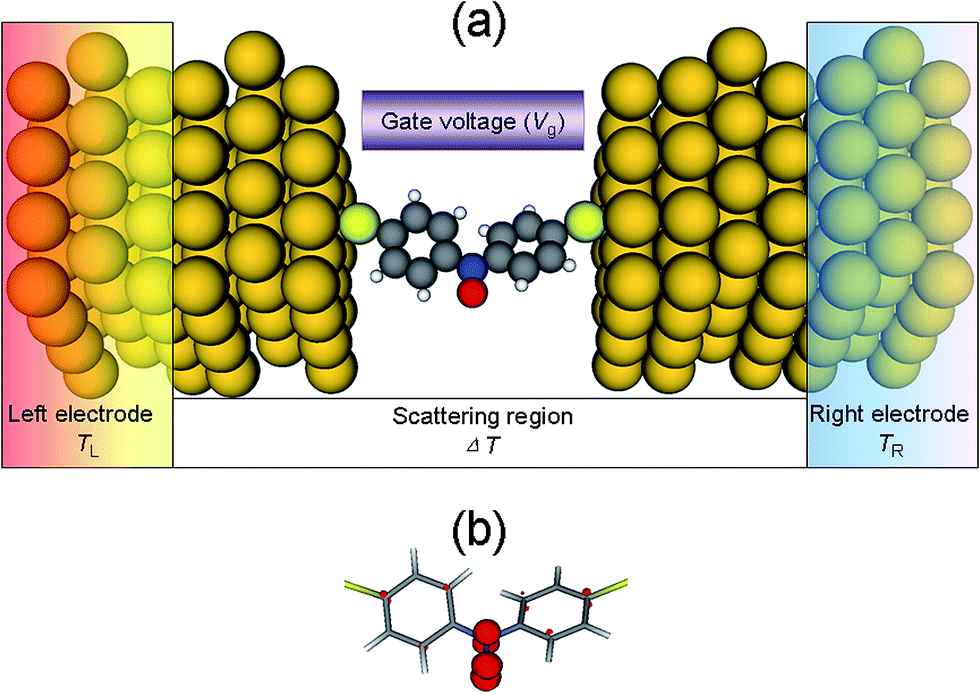 | ||
| Fig. 1 (a) The schematic illustration of the thermal spin caloritronic device, in which the nitroxide radical is sandwiched between two Au electrodes via phenylthiol groups. The sulfur atom is located at the hollow site of each Au surface. The thermal spin currents can be induced by applying a temperature difference (ΔT) between the left electrode (TL) and the right electrode (TR), i.e., ΔT = TL − TR. The gray, blue, red, white, yellow, and golden spheres indicate the carbon, nitrogen, oxygen, hydrogen, sulfur, and gold atoms, respectively. Vg is the transverse gate voltage. (b) The spin density distribution on the central molecule. | ||
The geometric optimization and the sequent thermal spin transport properties are performed within the framework of the Atomistix Toolkit (ATK) package,24–27 which adopts spin-polarized DFT combined with NEGF method. Norm-conserving Troullier–Martins pseudopotentials28 and a double-ξ plus polarization (DZP) basis set are adopted to describe the core orbitals and the valence electronic orbitals of all the atoms, respectively, except a single-ζ plus polarization (SZP) basis set is adopted for the valence electronic orbitals of Au atoms to achieve a balance between accuracy and computation burden. The exchange–correlation potential is treated at the level of spin-polarized generalized gradient approximation (GGA), with the form of Perdew–Burke–Ernzerhof.29 The Brillouin zone is sampled as a Monkhorst–Pack grid30 using 3 × 3 × 100 k-points and the grid mesh cutoff is set to 200 Ry. The spin-dependent current through the junction is given by the Landauer–Büttiker formula31
 | (1) |
| Tσ = Tr[ΓLGRΓRGA]σ, | (2) |
3 Results and discussion
The ground state of optimized free molecule is found to be a doublet-state with an unpaired spin-up electron. However, the presence of an unpaired electron in the free molecule does not necessarily give rise to polarized electron transmission, since charge transfer takes place once the molecule is connected to the electrodes and this maybe extinguish the excess number of spin-up electrons. According to the Mulliken population analysis, the number of excess spin-up electrons of the radical molecule in the junction is still found to be about 0.60e, which is mainly localized on the nitroxide radical group, as demonstrated by the spin density distribution in Fig. 1(b). Then, Fig. 2 plots the corresponding spin-resolved transmission spectrum, where the Fermi level (EF) has been set as the energy origin. Clearly, the transmission spectrum has an obvious asymmetric feature between spin-up and spin-down electrons, which can be ascribed to the asymmetric alignment between the EF and spin-polarized frontier molecular orbitals (FMOs). Around the EF, there are two peaks, at −0.17 eV for spin-up and 0.37 eV for spin-down, which originates from the delocalized highest occupied molecular orbital (HOMO) of spin-up electron and the lowest unoccupied molecular orbital (LUMO) of spin-down electron, respectively, as shown in the insets of Fig. 2. All these characteristics portend a potential way of applying the nitroxide radical-based molecule in the molecular spintronics. Here, we must point out that these two FMOs are calculated from the molecular projected self-consistent Hamiltonian (MPSH), which includes the molecule–electrode interaction.32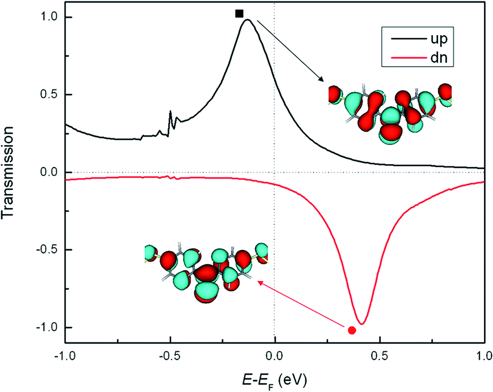 | ||
| Fig. 2 The spin-resolved transmission spectra. The positions of the HOMO and LUMO for spin-up and spin-down electrons are marked by black square and red circle, respectively. Both the temperatures of TL and TR are set as 300 K. The Fermi level (EF) has been set as the energy origin. The insets show the spatial distribution of HOMO and LUMO orbitals. | ||
Then, we apply different temperatures (TL and TR) to the left and right Au electrodes to investigate the thermal spin transport properties of the junction. The thermally induced spin currents versus the temperature difference ΔT (i.e., TL − TR) with different TL (100, 200, and 300 K) and those versus TL with different ΔT (20, 40, 60 and 80 K) are plotted in Fig. 3(a) and (b), respectively. Interestingly, a distinct spin Seebeck effect can be observed in the junction: the spin-up current (Iup) flows from the left electrode to the right one while the spin-down current (Idn) flows in the opposite direction. In this process, the dissipating heat is converted into spin voltage. Furthermore, the amplitude of Iup is always larger than that of Idn at the same ΔT and TL, and both of them go up almost linearly as ΔT and TL increase.
 | ||
| Fig. 3 (a) The thermal spin currents versus ΔT with different TL. (b) The thermal spin currents versus TL with different ΔT. | ||
According to the Landauer–Bütiker formula, the thermally induced current is determined not only by the transmission, but also by the difference in the Fermi–Dirac distributions between the left and right electrode, (fL(E, TL) − fR(E, TR)), which is only dependent on TL and TR, i.e., the carrier concentration on the left and right electrode, since the electrodes are the same material. Fig. 4(a) and (d) present the (fL(E, TL) − fR(E, TR)) with different TL (ΔT = 40 K) and ΔT (TL = 300 K), respectively, which shows a typical exponential decaying nature and also a perfect symmetric feature with respect to the EF. Clearly, fL − fR > 0 when the energy is higher than the EF, so carriers (electrons) with energy greater than the EF flow from the left electrode to the right one, resulting in a negative current in the opposite direction sine the electron charge e is negative. On the other hand, fL − fR < 0 when the energy is lower than the EF, thus, carriers (holes) with energy smaller than the EF flow from the left electrode to the right one, leading to a positive current. As shown in Fig. 4(a), although the height of fL − fR is decreased, it has a wider spread around the EF with the increase of TL if ΔT keeps constant. This means that the transmission with energy far from the EF can also contribute to the current as TL increases. On the contrary, as shown in Fig. 4(d), the distribution of fL − fR is nearly unchanged, although its height is increased with the increase of ΔT if TL is fixed, indicating the current is only determined by the transmission close to the EF.
 | ||
| Fig. 4 (a) The difference in the Fermi–Dirac distributions between the left and right electrode (fL(E, TL) − fR(E, TR)) for different TL. (b) The spin-up current spectra for different TL. (c) The spin-down current spectra for different TL. In (a)–(c), the ΔT is fixed at 40 K. (d)–(f) Similar to (a)–(c), respectively, except for different ΔT with a fixed TL = 300 K. | ||
Moreover, it is evident that the positive and negative currents will cancel out each other if the transmission spectrum is symmetric around the EF. In other words, an asymmetric distribution of the transmission spectrum around the EF is required to generate the thermally induced current. To further elucidate this point, the current spectra, Jσ(E) = Tσ(E)[fL(E, TL) − fR(E, TR)], as a function of energy, are shown in Fig. 4(b) and (e) (Fig. 4(c) and (f)) for spin-up electrons (spin-down electrons). Clearly, all these Jσ(E) are asymmetric with respect to the EF due to the asymmetry of corresponding Tσ(E). To be specific, for spin-up electrons (Fig. 4(b) and (e)), the cover area of Jup(E) below the EF is larger than that above the EF at a given TL and ΔT, resulting in a positive net spin-up current. On the contrary, for spin-down electrons (Fig. 4(c) and (f)), the cover area of Jdn(E) above the EF is larger than that below the EF at a certain TL and ΔT, giving rise to a negative net spin-down current. With the increase of TL (ΔT) in Fig. 4(b) and (c) (Fig. 4(e) and (f)), the asymmetry of Jσ(E) around the EF is enhanced. As a result, both the spin-up and spin-down currents increase almost linearly in Fig. 3. Moreover, the cover area of Jdn(E) is obvious smaller than that of Jup(E) due to the spin-down transmission peak Tdn(E) is farther than the spin-up transmission peak Tup(E) from the EF (Fig. 2). As a result, the amplitude of Idn is always smaller than that of Iup at the same TL and ΔT.
We have shown above that spin Seebeck effect can be obtained in the junction. Next, we prove that it is possible to create a pure spin current Is (the difference between the spin-up and spin-down currents, i.e., Is = Iup − Idn) for vanishingly charge current Ic (the sum of the spin-up and spin-down currents, i.e., Ic = Iup + Idn), and a completely spin-polarized current by tuning the transverse gate voltage Vg. The former has important applications in ISHE,13,14 while the later can be used to design a perfect spin-filter. Fig. 4(a) plots the Iup and Idn as a function of Vg for a fixed TL (300 K) and ΔT (40 K). At negative Vg, the amplitude of Iup increases firstly, and then decreases slowly. At positive Vg, the amplitude of Iup also increases firstly, then drops quickly to zero at Vg = 1.7 V. After that, Iup changes its sign from positive to negative. On the contrary, the amplitude variation of Idn is very small. In Fig. 5(b), we present the corresponding Ic and Is as a function of Vg. Clearly, a pure spin current appears at Vg = −1.98 and 1.65 V, respectively, where Ic = 0 and Is ≠ 0. Moreover, the spin polarization of charge current (SP = [(|Iup| − |Idn|)/(|Iup| + |Idn|)] × 100%) versus Vg is also shown in Fig. 5(b). It is evident that the SP reaches −100% at Vg = 1.7 V, where Iup = 0 and Idn ≠ 0.
 | ||
| Fig. 5 (a) The thermal spin-up and spin-down currents as a function of gate voltage Vg, where the TL and ΔT are set as 300 and 40 K, respectively. (b) The spin and charge currents, along with the spin polarization (SP) of the charge current versus Vg. | ||
To understand the variations of Iup and Idn, in Fig. 6, we plot the spin-resolved transmission spectrum under different Vg. As shown in Fig. 6(a), when negative Vg is applied, the Tup(E) takes place left-shift. Thus, the asymmetric distribution of Tup(E) around the EF is enhanced firstly, and then is weakened within the nonzero region of fL − fR (see the curve of TL = 300 K in Fig. 4(a) or ΔT = 40 K in Fig. 4(d)) when the negative Vg further increases, resulting in the corresponding increase and decrease of the amplitude of Iup. As shown in Fig. 6(b), when postive Vg is applied, the Tup(E) occurs right-shift and moves from below the EF to above the EF. In this process, the asymmetric distribution of Tup(E) with respect to the EF within the nonzero region of fL − fR is enhanced firstly, then is weakened, and then is completely eliminated at Vg = 1.7 V (not shown here), and then is enhanced again with the increase of Vg. As a result, the amplitude of Iup increases firstly, then drops quickly to zero at Vg = 1.7 V, and after that, the Iup changes its sign. On the other hand, as shown in Fig. 6(a) and (b), the Tdn(E) always moves to the left, no matter what Vg is applied. However, because the Tdn(E) is far from the EF, its shift can hardly affect the asymmetric distribution of Tdn(E) around the EF within the nonzero region of fL − fR. Therefore, the variations of Idn is very smooth.
 | ||
| Fig. 6 The spin-resolved transmission spectra with different Vg. | ||
4 Summary
In summary, by using spin-polarized first-principles density functional theory combined with nonequilibrium Green's function method, we have investigated the thermal spin transport properties of a nitroxide radical-based molecule sandwiched between two Au electrodes. The numerical results show that the spin Seebeck effect with spin-up and spin-down currents flowing in opposite directions can be realized by applying a temperature difference between two electrodes. The reason is ascribed to the asymmetric distribution the spin-resolved transmission spectra with respect to the Fermi level. Moreover, a pure spin current and a completely spin-polarized current can be achieved by tuning the transverse gate voltage. These results might be helpful in the design of organic radical-based spin caloritronic and spintronic devices.Acknowledgements
This work was jointly supported by the National Natural Science Foundation of China (Grant no. 11104115), the Science Foundation of Middle-aged and Young Scientist of Shandong Province of China (Grant no. BS2013DX036) and the Doctoral Foundation of University of Jinan, China (Grant no. XBS1004).References
- A. Aviram and M. A. Ratner, Chem. Phys. Lett., 1974, 29, 277–283 CrossRef CAS
.
- S. A. Wolf, D. D. Awschalom, R. A. Buhrman, J. M. Daughton, S. von Molnár, M. L. Roukes, A. Y. Chtchelkanova and D. M. Treger, Science, 2001, 294, 1488–1495 CrossRef CAS PubMed
- I. Žutić, J. Fabian and S. Das Sarma, Rev. Mod. Phys., 2004, 76, 323–410 CrossRef
- A. Fert, Rev. Mod. Phys., 2008, 80, 1517–1530 CrossRef CAS
- T. T. M. Vo, A. J. Williamson, V. Lordi and G. Galli, Nano Lett., 2008, 8, 1111–1114 CrossRef CAS PubMed
- G. Joshi, H. Lee, Y. Lan, X. Wang, G. Zhu, D. Wang, R. W. Gould, D. C. Cuff, M. Y. Tang, M. S. Dresselhaus, G. Chen and Z. Ren, Nano Lett., 2008, 8, 4670–4674 CrossRef CAS PubMed
- J. H. Lee, G. A. Galli and J. C. Grossman, Nano Lett., 2008, 8, 3750–3754 CrossRef CAS PubMed
- J. Tang, H. T. Wang, D. H. Lee, M. Fardy, Z. Huo, T. P. Russell and P. Yang, Nano Lett., 2010, 10, 4279–4283 CrossRef CAS PubMed
- G. E. W. Bauer, A. H. MacDonald and S. Maekawa, Solid State Commun., 2010, 150, 459–460 CrossRef CAS PubMed
- G. E. W. Bauer, E. Saitoh and B. J. van Wees, Nat. Mater., 2012, 11, 391–399 CrossRef CAS PubMed
- K. Uchida, S. Takahashi, K. Harii, J. Ieda, W. Koshibae, K. Ando, S. Maekawa and E. Saitoh, Nature, 2008, 455, 778–781 CrossRef CAS PubMed
- S. Valenzuela and M. Tinkham, Nature, 2006, 442, 176–179 CrossRef CAS PubMed
- E. Saitoh, M. Ueda, H. Miyajima and G. Tatara, Appl. Phys. Lett., 2006, 88, 182509 CrossRef PubMed
- T. Kimura, Y. Otani, T. Sato, S. Takahashi and S. Maekawa, Phys. Rev. Lett., 2007, 98, 156601 CrossRef CAS
- M. Zeng, Y. Feng and G. Liang, Nano Lett., 2011, 11, 1369–1373 CrossRef CAS PubMed
- D. D. Wu, H. H. Fu, L. Gu, Y. Ni, F. X. Zu and K. L. Yao, Phys. Chem. Chem. Phys., 2014, 16, 17493–17498 RSC
- Z. Su, Y. An, X. Wei and Z. Yang, J. Chem. Phys., 2014, 140, 204707 CrossRef PubMed
- A. Rajca, Chem. Rev., 1994, 94, 871–893 CrossRef CAS
- C. Herrmann, G. C. Solomon and M. A. Ratner, J. Am. Chem. Soc., 2010, 132, 3682–3684 CrossRef CAS PubMed
- Y. Matsuura, Chem. Phys. Lett., 2015, 619, 23–26 CrossRef CAS PubMed
- A. Calder, A. R. Forrester, P. G. James and G. R. Luckhurst, J. Am. Chem. Soc., 1969, 91, 3724–3727 CrossRef CAS
- M. Tachibana, K. Yoshizawa, A. Ogawa, H. Fujimoto and R. Hoffmann, J. Phys. Chem. B, 2002, 106, 12727–12736 CrossRef CAS
- H. Sellers, A. Ulman, Y. Shnidman and J. E. Eilers, J. Am. Chem. Soc., 1993, 115, 9389–9401 CrossRef CAS
- J. Taylor, H. Guo and J. Wang, Phys. Rev. B: Condens. Matter Mater. Phys., 2001, 63, 121104(R) CrossRef
- J. Taylor, H. Guo and J. Wang, Phys. Rev. B: Condens. Matter Mater. Phys., 2001, 63, 245407(R) CrossRef
- M. Brandbyge, J. L. Mozos, P. Ordejón, J. Taylor and K. Stokbro, Phys. Rev. B: Condens. Matter Mater. Phys., 2002, 65, 165401 CrossRef
- J. M. Soler, E. Artacho, J. D. Gale, A. García, J. Junquera, P. Ordejón and D. Sánchez-Portal, J. Phys.: Condens. Matter, 2002, 14, 2745–2779 CrossRef CAS
- N. Troullier and J. Martins, Phys. Rev. B: Condens. Matter Mater. Phys., 1991, 43, 1993–2006 CrossRef CAS
- J. P. Perdew, K. Burke and M. Ernzerhof, Phys. Rev. Lett., 1996, 77, 3865–3868 CrossRef CAS
- H. J. Monkhorst and J. D. Pack, Phys. Rev. B: Solid State, 1976, 13, 5188–5192 CrossRef
- M. Büttiker, Y. Imry, R. Landauer and S. Pinhas, Phys. Rev. B: Condens. Matter Mater. Phys., 1985, 31, 6207 CrossRef
- K. Stokbro, J. Taylor, M. Brandbyge, J. L. Mozos and P. Ordejón, Comput. Mater. Sci., 2003, 27, 151–160 CrossRef CAS
| This journal is © The Royal Society of Chemistry 2015 |