Synthesis of different CuO nanostructures from Cu(OH)2 nanorods through changing drying medium for lithium-ion battery anodes

Lin Shi, Chenyao Fan, Chunxiao Sun, Zhimin Ren, Xinxin Fu, Guodong Qian and Zhiyu Wang*
State Key Laboratory of Silicon Materials, School of Materials Science and Engineering, Zhejiang University, Hangzhou 310027, China. E-mail: wangzhiyu@zju.edu.cn; Fax: +86-571-87952539; Tel: +86-571-87952539

Received 21st December 2014 , Accepted 17th March 2015

First published on 17th March 2015


Abstract

Different CuO nanostructures have been successfully synthesized through changing the drying medium of Cu(OH)2 nanorods precursors. Herein, Cu(OH)2 nanorods precursors were first prepared through a simple precipitation method. When H2O was chosen as the drying medium at 80 °C, 2D leaf-like CuO nanostructures were obtained. While dried in ethanol 1D Cu(OH)2 nanorods were obtained. With post-annealing, porous CuO nanoleaves and nanocrystalline-assembled CuO nanorods were successfully synthesized, respectively, which have been applied to lithium batteries as anode materials and influence of different nanostructures on the electrochemical properties have been investigated. Fortunately, both novel nanostructured CuO successfully displayed high capacity and excellent cycling stability, and porous CuO nanoleaves can exhibit a reversible capacity of 633 mA h g−1 and 576 mA h g−1 after 100 and 150 discharge–charge cycles at 67.4 mA g−1, which is superior to that of CuO nanoleaves without post-annealing. These results may provide valuable insights for the industrialization and development of new nanostructured anodes for next-generation high-performance lithium-ion batteries.

Introduction

Lithium ion batteries (LIBs) have been regarded as the most powerful energy source for future portable electronic devices and great efforts have been devoted to developing high power density, high energy density and high safety LIBs for hybrid electric vehicles (HEV), plug in hybrid electric vehicles (PHEV) and pure electric vehicles (PEV).1–5 However, current commercially used graphite with theoretical capacity of 372 mA h g−1 as the anode material may not meet the growing high demand of future energy storage devices, thus transition-metal oxides with much higher theoretical capacity and better rate properties, which have been widely investigated as potential anode materials in recent years.6–9 3d transition metal oxides (MxOy, M = Fe, Co, Mn, Cu, Ni, etc.) can act as anodes via the so-called redox or “conversion” reaction with Li. Unfortunately, severe electrode pulverization caused by the large volume and structure variation of the transition metal oxides based anodes during discharge–charge process leads to poor cycling performance and fast capacity fade and blocks their widely commercial application.6,10

Copper oxide (CuO), as a narrow gap (1.2 eV) semiconductor has been considered as a promising anode material and has been extensively investigated recently due to its relatively high specific capacity (674 mA h g−1), easy to synthesize, low cost and environmental benignity except for fast capacity fade upon cycling.11–13

Many attempts to improve the electrochemical property of CuO-based anode materials have been made including synthesis of composites with carbon or conducting polymer such as carbon nanotube, graphene, mesoporous carbon, polypyrrole and so on.14–18 In this way, the electronic conductivity of electrode materials has been largely improved and the volume change during Li+ insertion/extraction has been relieved. However, the whole process is complex and inevitably costly which impedes its practical application. Another effective way is controlled synthesis of various CuO nanostructures. For example, Wang et al. fabricated highly porous CuO nanorods via heat treatment of Cu(OH)2 precursor, which delivered a high reversible capacity of 654 mA h g−1 at a rate of 0.5 C and excellent high rate capacity of 410 mA h g−1 even at 6 C.19 Complex three dimensional CuO nanowalnuts were prepared from the same diluted copper nitrate solution with ethanolamine at room temperature and 10 °C by Yu et al. which demonstrated a reversible capacity of 407 mA h g−1 after 30 cycles at a rate of 0.1 C.20 What's more, Ju et al. successfully synthesized multi-shelled CuO hollow structures using cetyltrimethylammonium bromide (CTAB) multi-lamellar as solf templates, which could exhibit a discharge capacity of 400 mA h g−1 at 150 mAg−1 after 50 cycles, and Wang et al. obtained leaf-like CuO, oatmeal-like CuO, and hollow-spherical CuO by changing the ligand agents, all of which delivered competitive electrochemical performance.21,22 Besides, CuO nanorods and nanosheets supported on a Cu substrate have been rationally fabricated from Cu2(OH)3NO3 precursors by Wang et al. through changing the solvents, and the unique nanostructural features endowed them high capacities of 450–650 mA h g−1 at 0.5–2 C over 100 cycles.23 Therefore, facile synthesis of new CuO nanostructures such as porous structure, hollow structure, 3D structure and nanocrystalline-assembled structure24 for lithium-ion battery is a promising way to obtain excellent electrochemical properties.

However, in most fore-mentioned methods, Cu(OH)2 is chosen as a morphology-controlled precursors for the synthesis of CuO nanostructures which inherit the special morphologies from Cu(OH)2, such as nanorods,19 nanowalnuts,20 and cog-like superstructures.25 And these methods involved in controlling the composition and morphology on property through modulation of reagent, reagent concentration, time, and surfactant. In this work, we gained two different CuO nanostructures from the same Cu(OH)2 precursor by simply changing the drying condition. When the rod-like Cu(OH)2 precursor was dried in deionized water, leaf-like CuO was obtained, after post-annealing at different temperatures leaf-like CuO turned to be porous. Wang et al. used citrate acid as a structure-directing agent successfully synthesized nanocrystalline-assembled bundle-like CuO nanostructure which endowed it with high rate capacities of 666 mA h g−1, and 609 mA h g−1 at a current rate of 0.3 C and 1 C, respectively.24 Here, we just replaced the deionized water with ethanol as the drying medium, nanocrystalline-assembled rod-like CuO were also successfully prepared when the Cu(OH)2 nanorods precursors were calcinated at different temperatures. Electrochemical performances of all the CuO electrodes were investigated and both porous leaf-like CuO and nanocrystalline-assembled rod-like CuO exhibited remarkably enhanced cycling performance and high reversible capacity. These results indicate that the development of anodes with special nanostructures such as porous structures, nanocrystalline-assembled structures is promising for next-generation high-performance LIBs.

Experimental section

Materials

Copper sulfate pentahydrate (CuSO4·5H2O ≥ 99.0%), sodium hydroxide (NaOH), ammonium hydroxide (wt% = 25% NH3·H2O) and cetyltrimethylammonium bromide (CTAB) were purchased from Shanghai Chemical Regent Co. and used as received without further purification.

Preparation of porous CuO nanoleaves

Firstly, 4.00 g of CuSO4·5H2O was dissolved in 200 mL solution mixed with 120 mL deionized water and 80 mL ethanol in a 500 mL beaker under constant magnetic stirring for 30 min, followed by addition of 200.00 mg CTAB. Then, 2 mL of 13.2 M ammonium hydroxide aqueous solution was diluted with 200 mL deionized water and before this solution dropwise added in the mixture was also maintained under continuous vigorous stirring at room temperature for another 30 min. Subsequently, 40 mL of 0.75 mol L−1 NaOH solution was added and a blue precipitate of Cu(OH)2 was obtained. The mixture was stirred for another 2 h, and then sealed for 20 h at ambient temperature. The product (denoted as sample A) was harvested by centrifugation, washed with deionized water and absolute alcohol several times, dispersed in 100 mL of deionized water and then dried in an oven at 80 °C, yielding a black CuO powder.

Preparation of nanocrystalline-assembled CuO nanorods

The synthesis procedure of the rod-like CuO was the same as that of the leaf-like CuO except that the blue precipitate of Cu(OH)2 was dispersed in ethanol and then dried in an oven at 80 °C. The product obtained was denoted as sample B.

Sample A and sample B were further annealed in air at 200 °C or 400 °C for 6 h, denoted as A-200, A-400, B-200 and B-400, respectively.

Materials characterization

The structure determination was characterized by powder X-ray diffraction (XRD; Philips, PW1050, Cu Kα radiation, λ = 1.5406 Å). Morphology and structure of samples were investigated using transmission electron microscopy (TEM; JEOL, JEM-1230) operating at an accelerating voltage of 80 kV and scanning electron microscopy (SEM; HITACHI-4800). The structure and selected area electron diffraction were measured by High-resolution TEM (HRTEM; TECNAI G2 F20) at 200 kV. Nitrogen adsorption and desorption were conducted employing Tristar II 3020 surface and porosity analyzer at 77 K. The surface area was calculated using the Brunauer–Emmett–Teller (BET) equation. The pore size distribution was estimated from the desorption branch of the isotherm curves using the Barrett–Joyner–Halenda (BJH) model. Thermogravimetric analysis (TGA) was performed using a CHNS/O analyzer (PE 2400II, PerkinElmer, America) in air atmosphere from room temperature to 800 °C with a heating rate of 10 °C min−1.

Electrochemical measurement

The electrochemical characterization was performed with CR2025-type coin cells containing the CuO working electrode and metallic lithium foil as the counter electrode. The working electrodes were prepared by mixing 80 wt% active material (CuO), 10 wt% acetylene black and 10 wt% polyvinylidene fluoride (PVDF) binder dispersed in N-methyl-2-pyrrolidinone. After uniformly coating the above slurry on Cu foils, the electrodes were dried in a vacuum oven at 120 °C for 12 h to remove the solvent before pressing. Celgard 2400 polypropylene membrane was used as a separator and the electrolyte consisted of 1 M LiPF6 in a mixture of 1[thin space (1/6-em)]:[thin space (1/6-em)]1[thin space (1/6-em)]:[thin space (1/6-em)]1 (v/v/v) ethylene carbonate (EC)–dimethyl carbonate (DMC)–diethyl carbonate (DEC). The cells were assembled in an argon-filled glove box. The galvanostatic discharge–charge cycles were tested by LAND CT2001A battery test system (Wuhan Land Electronic Co., China) at a constant current density of 0.1 C (1 C = 674 mA h g−1) based on the weight of the CuO sample between 3 V and 0.001 V vs. Li+/Li at room temperature. Cyclic voltammetry (CV) was conducted on an Arbin electrochemical workstation at a scan rate of 0.1 mV s−1 from 0 V to 3.0 V.

Results and discussion

The phase of the as-prepared samples (sample A, A-200, A-400, B, B-200, B-400) was examined by XRD as shown in Fig. 1. As for the leaf-like samples (samples A) in Fig. 1a, all the diffraction peaks can be indexed to the monoclinic symmetry of CuO (JCPDS file no. 45-0937, C2/c). However, in Fig. 1b all the diffraction peaks of sample B can be assigned to the orthorhombic symmetry of Cu(OH)2 (JCPDS file no. 35-0505, Cmcm). After heat treatment at 200 °C, and 400 °C, respectively, Cu(OH)2 precursor turned into CuO phase which is the same as that of samples A. No additional peaks were detected. It can be observed that the half-peak width of sample B-200 is larger than that of sample B-400 from the XRD pattern, which indicates that the crystallites of sample B-200 are smaller.
image file: c4ra16778c-f1.tif
Fig. 1 XRD patterns of: (a) samples A and (b) samples B.

The typical images of the synthesized leaf-like CuO nanostructure samples before and after calcination are shown in Fig. 2. Whether they were calcinated or not, samples A exhibit a leaf-like morphology. In Fig. 2a, leaf-like CuO nanostructures are of uniform sized, about 350–450 nm long and 200 nm wide. These leaves are composed of nanoribbons as clearly exhibited in TEM image (Fig. 2b). After calcination, especially at 400 °C, two sides of the CuO leaves turned to be smoother than before as presented in Fig. 2c–d and S1.


image file: c4ra16778c-f2.tif
Fig. 2 (a) SEM and (b) TEM images of as-prepared CuO nanoleaves obtained at 80 °C (sample A); (c) SEM and (d) TEM images of as-prepared porous CuO nanoleaves obtained at 400 °C (simple A-400); (e) and (f) HRTEM images of an individual CuO nanoleaf, and inset is its corresponding selected area electron diffraction pattern.

What's more, from the distinct black and white contrasts in the CuO leaves we may conclude that sample A-400 is porous nanoleaves, the pore sizes distribution is around 3–15 nm, the average pore size is 10 nm and the BET surface area was calculated to be 12 m2 g−1 (Fig. S2). Due to further dehydration and substantive characteristics of leaf-like CuO which is self-aggregation of nanoribbons, abundant pores formed in the leaf-like nanosheets.19,24,26 According to the selected area electron diffraction pattern (inserted in Fig. 2e), these nanograins are inclined to align along direction of [010], nevertheless the slightly elongated spots in the pattern indicate that the quasi-single crystalline character of the leaf-like nanosheets which were formed via an “oriented attachment” process.27 A high-resolution TEM image shown in Fig. 2f exhibits the crystal lattices of a single nanoleaf, and fringes with spacings of ca. 0.275 nm, corresponds to the (110) plane of monoclinic-phase CuO.

When ethanol was used as a dispersant during the drying process, instead of leaf-like CuO, Cu(OH)2 nanorods were obtained as shown in Fig. 3. The Cu(OH)2 nanorods of ∼20 nm in average diameter and 1–2 μm in length were inclined to arrange along a certain direction, which can be observed from the SEM characterization (Fig. 3a). The thermal behavior of the Cu(OH)2 nanorods precursor was investigated by thermogravimetric analysis (TGA). The TGA result (Fig. S3) shows that from room temperature to 750 °C the precursor underwent a 18.35 wt% weight loss due to thermal dehydration, which is in agreement with the theoretical weight loss of Cu(OH)2.


image file: c4ra16778c-f3.tif
Fig. 3 (a) SEM image of as prepared Cu(OH)2 nanorods obtained at 80 °C (sample B); (b) SEM image of as prepared nanocrystalline-assembled CuO nanorods obtained at 200 °C (sample B-200); (c) SEM, (d) TEM, (e) and (f) HRTEM images of as prepared nanocrystalline-assembled CuO nanorods obtained at 400 °C (sample B-400), and inset is corresponding selected area electron diffraction pattern.

After heat treatment at 200 °C for 6 h, the CuO products maintained the rod-like morphology from their precursors which can be seen clearly from the SEM characterization (Fig. 3b) and TEM examination (Fig. S4), but every nanorod has turned to be granular due to the dehydration of Cu(OH)2 in the calcination process which is similar to the work of Wang et al.24 and the boundary between nanograins can be observed from the TEM image (Fig. S4). With the rising of the calcination temperature to 400 °C, the morphology of the CuO nanorods turned to be crooked necklace though nanograins are not of uniform size which is shown in Fig. 3c–d. Fig. 3e shows the HRTEM image of two CuO nanorods, from which nanograins can be seen even more clearly. For the CuO nanorods, the spots of nanograins formed concentric circle in the SAED pattern (inset in Fig. 3e) corresponds to the (−111) plane of reflection for monoclinic CuO. Lattice images in Fig. 3f showed fringes with spacings of ca. 0.275 nm and ca. 0.250 nm, which correspond to monoclinic-phase CuO.

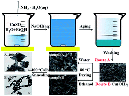
The overall schematic model of the synthetic procedure is presented in Fig. 4. It's worth noting that, in this work, Cu(OH)2 is first used as morphology-controlled precursor and then two intermediate products (sample A and B) act as precursors for the final products porous leaf-like CuO and nanocrystalline-assembled rod-like CuO. When the diluted ammonium hydroxide aqueous solution was added in, Cu2+ reacted with NH3·H2O, forming a homogeneous deep blue [Cu(NH3)n]2+ (n = 1–4) solution.28 Upon adding NaOH solution, NH3 in the [Cu(NH3)n]2+ complex was replaced by OH to form square-planar [Cu(OH)4]2− units, resulting in the formation of orthorhombic Cu(OH)2. The chemical reactions in the solution accord to equations:29,30,32

 
Cu2+ + nNH3·H2O → [Cu(NH3)n]2+ + nH2O (1)
 
[Cu(NH3)n]2+ + 2OH + nH2O → Cu(OH)2 + 2nNH3·H2O (2)
 
Cu2+ + 2OH → Cu(OH)2 (3)


image file: c4ra16778c-f4.tif
Fig. 4 Schematic illustration of the synthesis processes of as-prepared CuO nanostructures.

Therefore, individual Cu(OH)2 nanoparticles were formed at the beginning, and then the primary nanoparticles oriented attached to form Cu(OH)2 nanorods and grew preferentially along the [100] direction.28 During the drying process, the temperature increased to 80 °C and due to the presence of excess OH derived from the dissociation of H2O, the orthorhombic Cu(OH)2 nanorods transformed to leaf-like monoclinic CuO nanostructure by a dehydration reaction through breaking the interplanar H-bonds.30 So there must be two steps for the transformation of rod-like Cu(OH)2 to leaf-like CuO in deionized water at 80 °C: one is the oriented attachment of Cu(OH)2 nanorods to form 2D CuO nanoleaves; the other one is the dehydration of Cu(OH)2 to CuO. While sample B dried in ethanol maintained the rod-like morphology of Cu(OH)2 nanorods. The above results demonstrate that different CuO nanostructures can be controllable synthesized by using different drying mediums. All of these may attribute to the much more active hydroxyl of H2O than that of ethanol and metastable state of the initial Cu(OH)2. What's more, the solvent polarity and solubility of the drying medium may also play an important role in the synthesis of CuO nanostructures.23,31

In order to evaluate the applicability of the two kinds of novel CuO nanostructures, we investigated the electrochemical properties of both porous leaf-like CuO (sample A and sample A-400) and nanocrystalline-assembled rod-like CuO (sample B-400) samples by a galvanostatic method. Fig. 5a–c reveals the representative first three CV curves of different synthesized CuO samples. In the first cathodic scan process (lithiation process), three cathodic peaks are observed similarly for all the three as-prepared CuO samples at 1.60 V, 0.97 V, and 0.85 V in the potential range of 0.0–3.0 V which indicates a multi-step electrochemical reaction of CuO, associated with the creation of a Cu1−xIICuxIO1−x/2 intermediate, a Cu2O phase, and reduction to Cu and Li2O as reported previously.22,33,34 Hence, the overall electrochemical reaction can be described as follows:

CuO + 2Li+ + 2e ↔ CuO + Li2O


image file: c4ra16778c-f5.tif
Fig. 5 (a–c) Cyclic voltammograms and (d–f) selected discharge–charge curves of as prepared CuO samples: (a and d) sample A; (b and e) sample A-400; (c and f) sample B-400.

Apparently, the three cathodic peaks correspond to three phase transformation process. For the high potential near 1.60 V, it involves the formation of Cu1−xIICuxIO1−x/2 solid-solution when a limited amount of Li insert into CuO electrode.35 Then, the solid-solution transforms into Cu2O phase at 0.97 V with another electrochemical reaction. Further transformation of Cu2O into Cu and Li2O is expected to occur at a potential around 0.85 V. What's more, the formation of a solid electrolyte interface (SEI) layer on the electrode surface and irreversible electrolyte decomposition also go with the electrochemical process.36,37

Though three cathodic peaks at similar potential are observed for the different as-prepared CuO samples during the cathodic scan process, some differences are also noticeable. Sample A-400 exhibits one comparative strong cathodic peak at 0.74 V which is accompanied with the transformation of Cu2O into Cu particles and Li2O, and reversible formation/decomposition of a polymeric gel-like film on the surface of the particles, these may ascribe to the porous structure provides sufficient contact between CuO and the electrolyte that enhances these reactions.14,35 In addition, these reactions are favorable for the better reaction reversibility during the discharge–charge process, thus improve the electrochemical performance.19,38

In the first anodic scan process (delithiation process), the three CuO samples exhibit a similar oxidation peak at 2.43 V which is associated with the formation of Cu2O, and a anodic peak near 2.69 V, attributed to partial oxidation of Cu2O to CuO and this transformation during cycling leads to volume change and decrease of cycling life. In the subsequent anodic process, the anodic peak at 2.73 V is still found for sample B-400, which indicates an excellent conversion reaction reversibility of this sample and also leads to worrying about the cycle stability.

During the subsequent cycles, the cyclic voltammograms of the as-prepared CuO samples are basically overlapped and all the cathodic and anodic peaks slightly shift to higher potentials with very good reproducibility, indicating good reversibility during the electrochemical process.

The representative galvanostatic discharge–charge curves of various CuO samples for the 1st, 2nd, 20th, 50th, and 100th cycles recorded at a 0.1 C rate are also shown in Fig. 5d–f, which exhibits multiple plateaus in the charge curves indicate that multi-step electrochemical reactions between CuO and lithium during the conversion process. These results are consistent with the CV curves ahead. The initial charge and discharge capacities of the sample A-400 are 961.77 mA h g−1 and 579.32 mA h g−1. Compared with the theoretical capacity of CuO, the extra capacity of initial discharge is probably due to the reversible formation and decomposition of a polymeric gel-like layer as proposed by Tarascon et al.33 Thus, an irreversible capacity loss is found for the sample A-400 and as well as others, which should be attributed to the decomposition of electrolyte and formation of SEI layers. In subsequent cycles, the shapes of the curves do not change significantly, suggesting good capacity retention.

Fig. 6 shows the cycling performance and rate performance of the leaf-like CuO and nanocrystalline-assembled rod-like CuO electrodes. In Fig. 6a, it is the leaf-like CuO before calcination and its capacity drops after several cycles with only 16.45% retention of the second reversible capacity (50th, 117 mA h g−1) in spite of a slightly increase of the capacity after the 60th cycle and reaches the maximum 170 mA h g−1 at 130th cycle. After calcination the porous leaf-like CuO (sample A-400) demonstrates an excellent electrochemical reversibility and even after 100 and 150 discharge–charge cycles (Fig. 6c), the capacity of it remains at a high reversible capacity of 633 mA h g−1 and 576 mA h g−1 at 0.1 C, which is better than many previous reports.20,22,39,40 Besides, sample A-200 also delivers promising cycling performance, the capacity of which can reach 472 mA h g−1 after 180 cycles in Fig. S5a. Moreover, both sample A-400 and A-200 undergo an increasing cycle capacity with cycle numbers, which may contribute to the activation of the leaf-like CuO especially the pores and the buildup of the SEI layer. As for the nanocrystalline-assembled rod-like CuO (sample B-400), the electrode delivers a reversible capacity of 602 mA h g−1 and 563 mA h g−1 after 100 and 150 cycles at 0.1 C, with 94.8% and 88.6% retention of the second reversible capacity. While, the capacity of sample B-200 (Fig. S5c) decreases fast, the second discharge and charge capacities are 847 and 792 mA h g−1 and after 100 cycles they decrease to 157 and 160 mA h g−1. The initial coulombic efficiency of sample A, sample A-400, and sample B-400 are 74%, 60% and 63%, respectively, and from the second cycle onwards the coulombic efficiencies are generally near 98%.


image file: c4ra16778c-f6.tif
Fig. 6 (a, c and e) Cycling performance and (b, d and f) rate capacity of the as-prepared CuO samples: (a and b) sample A; (c and d) sample A-400; (e and f) sample B-400.

Fig. 6b, d and f exhibit the rate capacity of the three CuO electrodes at different current densities. Overall, the porous leaf-like CuO (sample A-400) and the nanocrystalline-assembled rod-like CuO (sample B-400) show good rate capacity performance. It can be observed that sample A exhibits a fast capacity fade at rate of 0.1 C and 0.2 C for ten cycles, then its capacity remains lower than 100 mA h g−1 even when the rate turns back to 0.1 C. As for sample A-400, a discharge capacity of 648 mA h g−1 is obtained at 0.1 C after 10 cycles, and this value is slowly reduced to 510, 228, 151, 103 mA h g−1 when the current rate is consecutively set at the levels of 0.2 C, 0.5 C, 1 C and 2 C, respectively, then increases to 664 mA h g−1 at 0.1 C. Apparently, sample B-400 delivers a similar good rate capacity performance, but when the current rate returns back to 0.1 C, the discharge capacity decreases to 554 mA h g−1, which may attribute to structural damages during the high current rate cycles.

Here, both 2D porous leaf-like CuO and 1D nanocrystalline-assembled rob-like CuO show excellent electrochemical properties, thus nanostructure seems to be a vital factor to control electrochemical performance. As the porous CuO nanoleaves with pores (sample A-200, sample A-400) show better electrochemical properties than precursors CuO without pores (sample A), it might be reasonable to attribute this to its porous structures, which not only provide efficient contact area between electrolyte and electrode, leading to more facile Li+ transport in electrolyte within the pores, enhancing the conversion reaction taking place in the porous structures and improving the reversibility during the discharge–charge process, but also provide appropriate void space serves as an elastic buffer to relieve the volume expansion during the Li+ uptake/release, leading to high cycle stability. Otherwise, different pore size which can be controlled by changing the heat-treatment temperature will affect the electrochemical properties from the comparison of the two porous leaf-like CuO electrodes.19 As for the 1D nanocrystalline-assembled rod-like CuO, the cavities among the nanograins play a similar role as the pores in the nanoleaf above, which improve excellent cycling performance and rate capacity. However, the porous structure may work better than the nanocrystalline-assembled structure in reliving the strain induced by the severe volume variation of CuO during lithiation/delithiation process.

Conclusions

In conclusion, two different nanostructures, including 2D porous leaf-like CuO and 1D nanocrystalline-assembled rod-like CuO, have been successfully synthesized via a same, green and facile wet chemical procedure. It has been demonstrated that the nanostructures of CuO can be controlled by different drying medium. When they were applied as anode materials for LIBs, the porous leaf-like CuO can deliver a high reversible capacity of 576 mA h g−1 at 0.1 C after 150 cycles and an initial Coulombic efficiency of 60%, and the rod-like CuO can exhibit a reversible capacity of 563 mA h g−1 at 0.1 C and retain 94.8% of initial capacity after 150 cycles, indicating excellent cycling performance. While porous CuO nanoleaves exhibit much better rate performance than that of CuO nanorods. The improving electrochemical property is attributed to the advantageous nanostructures with pores or cavities, which are beneficial for the Li+ transport and the cushion of volume variation during the discharge–charge process. Thus, this facile synthetic method of producing two different CuO nanostructures with the same precursor and their excellent electrochemical performance will promote their application in the next-generation high-performance LIBs.

Acknowledgements

The authors gratefully acknowledge the financial support for this work from the National Natural Science Foundation of China (no. 51272231).

Notes and references

  1. M. Armand and J. M. Tarascon, Nature, 2008, 451, 652 CrossRef CAS PubMed.
  2. M. M. Thackeray, C. Wolverton and E. D. Isaacs, Energy Environ. Sci., 2012, 5, 7854 CAS.
  3. F. Cheng, J. Liang, Z. Tao and J. Chen, Adv. Mater., 2011, 23, 1695 CrossRef CAS PubMed.
  4. P. G. Bruce, B. Scrosati and J. M. Tarascon, Angew. Chem., Int. Ed., 2008, 47, 2930 CrossRef CAS PubMed.
  5. Z. Chen, M. Zhou, Y. Cao, X. Ai, H. Yang and J. Liu, Adv. Energy Mater., 2012, 2, 95 CrossRef CAS.
  6. M. V. Reddy, G. V. Subba Rao and B. V. R. Chowdari, Chem. Rev., 2013, 113, 5364 CrossRef CAS PubMed.
  7. H. B. Wu, J. S. Chen, H. Hoon Hng and X. W. Lou, Nanoscale, 2012, 4, 2526 RSC.
  8. J. Jiang, Y. Y. Li, J. P. Liu, X. T. Huang, C. Z. Yuan and X. W. Lou, Adv. Mater., 2012, 24, 5166 CrossRef CAS PubMed.
  9. P. Poizot, S. Laruelle, S. Grugeon, L. Dupont and J. M. Tarascon, Nature, 2000, 407, 496 CrossRef CAS PubMed.
  10. J. Cabana, L. Monoconduit, D. Larcher and M. R. Palacon, Adv. Mater., 2010, 22, E170 CrossRef CAS PubMed.
  11. S. Ko, J. I. Lee, H. S. Yang, S. Park and U. Jeong, Adv. Mater., 2012, 24, 4451 CrossRef CAS PubMed.
  12. A. S. Zoolfakar, R. A. Rani, A. J. Morfa, A. P. O'Mullane and K. Kalantar-zadeh, J. Mater. Chem. C, 2014, 2, 5247 RSC.
  13. Q. B. Zhang, K. L. Zhang, D. G. Xu, G. C. Yang, H. Huang, F. D. Nie, C. M. Liu and S. H. Yang, Prog. Mater. Sci., 2014, 60, 208 CrossRef CAS PubMed.
  14. Y. Zhang, M. W. Xu, F. Wang, X. P. Song, Y. H. Wang and S. Yang, J. Phys. Chem. C, 2013, 117, 12346 CAS.
  15. H. W. Huang, Y. Liu, J. H. Wang, M. X. Gao, X. S. Peng and Z. Z. Ye, Nanoscale, 2013, 5, 1785 RSC.
  16. J. W. Ko, S. W. Kim, J. Hong, J. Ryu, K. Kang and C. B. Park, Green Chem., 2012, 14, 2391 RSC.
  17. M. Yang and Q. M. Gao, Microporous Mesoporous Mater., 2011, 143, 230 CrossRef CAS PubMed.
  18. Z. G. Yin, Y. H. Ding, Q. D. Zheng and L. H. Guan, Electrochem. Commun., 2012, 20, 40 CrossRef CAS PubMed.
  19. L. L. Wang, H. X. Gong, C. H. Wang, D. K. Wang, K. B. Tang and Y. T. Qian, Nanoscale, 2012, 4, 6850 RSC.
  20. Q. Yu, H. W. Huang, R. Chen, P. Wang, H. S. Yang, M. X. Gao, X. S. Peng and Z. Z. Ye, Nanoscale, 2012, 4, 2613 RSC.
  21. J. H. Ju and K. S. Ryu, J. Electrochem. Soc., 2011, 158, A814 CrossRef CAS PubMed.
  22. C. Wang, Q. Li, F. F. Wang, G. F. Xia, R. Q. Liu, D. Y. Li, N. Li, J. S. Spendelow and G. Wu, ACS Appl. Mater. Interfaces, 2014, 6, 1243 CAS.
  23. Z. Y. Wang, F. B. Su, S. Madhavi and X. W. Lou, Nanoscale, 2011, 3, 1618 RSC.
  24. L. L. Wang, W. Cheng, H. X. Gong, C. H. Wang, D. K. Wang, K. B. Tang and Y. T. Qian, J. Mater. Chem., 2012, 22, 11297 RSC.
  25. W. X. Zhang, M. Li, Q. Wang, G. D. Chen, M. Kong, Z. H. Yang and M. Stephen, Adv. Funct. Mater., 2011, 21, 3516 CrossRef CAS.
  26. X. Chen, N. Q. Zhang and K. N. Sun, J. Mater. Chem., 2012, 22, 13637 RSC.
  27. C. M. Liu and S. J. Yang, ACS Nano, 2009, 3, 1025 CrossRef CAS PubMed.
  28. C. H. Lu, L. M. Qi, J. H. Yang, D. Y. Zhang, N. Z. Wu and J. M. Ma, J. Phys. Chem. B, 2004, 108, 17825 CrossRef CAS.
  29. Y. Qin, F. Zhang, Y. Chen, Y. J. Zhou, J. Li, A. W. Zhu, Y. P. Luo, Y. Tian and J. H. Yang, J. Phys. Chem. C, 2012, 116, 11994 CAS.
  30. X. J. Zhang, G. F. Wang, X. W. Liu, J. J. Wu, M. Li, J. Gu, H. Liu and B. Fang, J. Phys. Chem. C, 2008, 112, 16845 CAS.
  31. Y. N. Xia, P. D. Yang, S. X. Sun, Y. Y. Wu, B. Mayers, B. Gates, Y. D. Yin, F. Kim and Y. Q. Yan, Adv. Mater., 2003, 15, 353 CrossRef CAS.
  32. D. P. Dubal, G. S. Gund, R. Holze and C. D. Lokhande, J. Power Sources, 2013, 242, 687 CrossRef CAS PubMed.
  33. A. Débart, L. Dupont, P. Poizot, J. B. Leriche and J. M. Tarascon, J. Electrochem. Soc., 2001, 148, A1266 CrossRef PubMed.
  34. X. Wang, D. M. Tang, H. Q. Li, W. Yi, T. Y. Zhai, Y. Bando and D. Golberg, Chem. Commun., 2012, 48, 4812 RSC.
  35. R. Sahay, P. S. Kumar, V. Aravindan, J. Sundaramurthy, W. C. Ling, S. G. Mlhaisalkar, S. Ramarkrishna and S. Madhavi, J. Phys. Chem. C, 2012, 116, 18087 CAS.
  36. S. Laruelle, S. Grugeon, P. Poizot, M. Dollé, L. Dupont and J. M. Tarascon, J. Electrochem. Soc., 2002, 149, A627 CrossRef CAS PubMed.
  37. S. Choi, J. Lee and S. Park, J. Mater. Chem., 2012, 22, 22366 RSC.
  38. A. Vu, Y. Q. Qian and A. Stein, Adv. Energy Mater., 2012, 2, 1056 CrossRef CAS.
  39. C. Wang, D. Higgins, F. F. Wang, D. Y. Li, R. Q. Liu, G. F. Xia, N. Li, Q. Li, H. Xu and G. Wu, Nano Energy, 2014, 9, 334 CrossRef CAS PubMed.
  40. C. M. Zhang, J. Chen, Y. Zeng, X. H. Rui, J. X. Zhu, W. Y. Zhang, C. Xu, T. M. Lim, H. H. Hng and Q. Y. Yan, Nanoscale, 2012, 4, 3718 RSC.

Footnote

Electronic supplementary information (ESI) available: See DOI: 10.1039/c4ra16778c

This journal is © The Royal Society of Chemistry 2015
Click here to see how this site uses Cookies. View our privacy policy here.