Tingting Qiang,
Jiaxin Fang,
Yixuan Song,
Qiuyang Ma,
Ming Ye,
Zhen Fang* and
Baoyou Geng*
Key Laboratory of Functional Molecular Solids, Ministry of Education, Center for Nano Science and Technology, College of Chemistry and Materials Science, Anhui Normal University, Wuhu, 241000, P. R. China. E-mail: fzfscn@mail.ahnu.edu.cn; bygeng@mail.ahnu.edu.cn
First published on 2nd February 2015
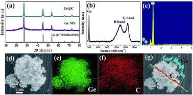
Ge@C core–shell nanostructures were successfully synthesized by a facile n-hexane pyrogenation-reducing process. The Ge@C core–shell nanostructures exhibit excellent cycling performance and rate capability in comparison with pure Ge nanoparticles when used as an anode material for a lithium ion battery. The thin carbon shell endows the obtained Ge@C nanostructures with a high specific capacity of 985 mA h g−1 at a current density of 500 mA g−1 after 50 cycles. Furthermore, a discharge capacity of 850 mA h g−1 was observed at a current density of 4000 mA g−1. The excellent lithium storage performance can be attributed to the unique carbon shell structure. The carbon shell not only acts as the buffer layer to maintain structural stability during lithiation, but also increases electrical conductivity during the charge/discharge processes. The high rate capacity of the Ge@C nanostructures demonstrates it a promising anode material for high power lithium-ion batteries.
As high capacity anode materials, silicon and germanium have attracted great attention recently. The theoretical capacities of Si and Ge are 4211 and 1624 mA h g−1, respectively.11 Compared with Si, Ge has a better prospect as a LIB anode material for the following reasons: (i) the electrical conductivity of Ge is 104 times higher than that of Si because of its smaller band gap of 0.6 eV. (ii) The Li diffusion coefficient in Ge is 400 times higher than that of Si at room temperature.12,13 Despite these superiorities, improving its poor cycle stability of germanium material is still a challenge. The reason for the capacity fading is huge volume change (more than 300%) during the Li insertion and extraction process.14 The huge volume change results in the pulverization of active material and exfoliation from the current collector, which interrupting the charge-transportation pathway and lead into irreversible capacity fading.15,16 To overcome this shortage, various efforts have been devoted to improve the cyclic performance of Ge, such as decreasing material particle size,17 using elemental alloys18 and novel electrolytes,19 coating with carbon shells20 and so on. Among the various methods, the coating active material with carbon shell is the effective way for improving the cycle performance. The carbon shell acts as a stable conducting framework during the Li uptake/release process, maintaining structural stability, increasing electrical conductivity and prevention of direct contact of Ge with the electrolyte.15 In the initial charge/discharge cycles, carbon coating can preventing subsidiary reactions and forming a stable solid electrolyte interphase (SEI) film, which result in superior electrochemical stability.21 On the other hand, decreasing the size of Ge particles into the nanoscale can mitigate the physical strains during the charge–discharge process, so the volume change causes less cracking and particle pulverization, which result in a certain enhancement in stability and cycle performance.17 For examples, Wang et al. synthesized Ge@C core–shell composites by carbonization of L-ascorbic acid, which exhibit 900 mA h g−1 at current of 800 mA g−1 after 50 cycles.20 Ge@C ellipsoidal structures were synthesized by the chemical vapor deposition (CVD) method through C2H2–Ar mixture. The capacity retention recorded was 83% (1137 mA h g−1) after 200 cycles at the 0.2 C.22
In this work, we report a facile method to synthesis of Ge@C core–shell nanostructures using an in situ n-hexane pyrogenation-reducing process. In this process, n-hexane not only acts as a carbon source but also reduces amorphous GeOx under high temperature. Comparing with Ge nanoparticles, the as prepared Ge@C core–shell nanostructures exhibits elevated cycling stability and an excellent rate performance in lithium-ion batteries.
:
1
:
1. The mixed slurry was pasted onto a Cu foil current collector and then dried in a vacuum oven at 70 °C for 6 h. The weight of the active materials on individual electrodes is 1 ± 0.2 mg. Coin metallic Li foils were used as both the counter and reference electrodes and polypropylene membranes used as the separator. The electrolyte consisted of a solution of 1 M LiPF6 in ethylene carbonate/diethyl carbonate (EC
:
DEC = 1
:
1, vol%). 2032 coin-type cells were assembled in an Ar-filled glove box (Mikrouna, Super (1220/750/900)) with concentrations of moisture and oxygen below 1.0 ppm. Electrochemical impedance spectroscopy (EIS) was measured on an AC voltage of 10 mV amplitude in the frequency range from 100 mHz to 100 kHz. The cells were galvanostatically charged and discharged on a Neware battery tester at various current densities within the voltage range 0.01–1.5 V. As the charge platform of Ge NPs is lower than that of Ge@C nanostructures, the charge–discharge voltage range of Ge NPs is 0.01–1 V.
SEM images (Fig. 2a and b) of the product show that the product is composed of uniform nanoparticles with sizes range from 50–100 nm. TEM images of the Ge@C nanostructures (Fig. 2c) clearly show the marked contrast between the crystalline Ge and the carbon. The dark Ge NPs are well-covered by carbon layer. In HRTEM image of the carbon-coated Ge (Fig. 3d),15 the thin and amorphous carbon layer is clearly observed with thickness of 8.5 nm, and crystalline planes of Ge 1/3(422) with a distance spacing of 0.34 nm can be clearly observed. The selected area electron diffraction (SAED, Fig. 2d inset) obtained from [111] zone axis corresponded to the formally forbidden reflections (d = 0.34 nm), which is often observed in cubic phase.28 The continuous carbon shell not only acts as a buffer layer between the individual Ge nanocrystals to alleviate the strain during lithiation, but also provide a stable conductive network during the charge/discharge processes.10 The surface area of these Ge@C core–shell structures further revealed by the Brunaue–Emmett–Teller (BET) analysis. Calculating from the N2 adsorption isotherm, the BET specific surface area of the Ge@C nanostructures is 8.4 m2 g−1 (Fig. S3†).
![]() | ||
| Fig. 2 (a and b) SEM image of the Ge@C nanostructures at different magnifications. (c) TEM image and (d) HRTEM images, SAED (inset) of Ge@C nanostructure. | ||
![]() | ||
| Fig. 3 The first three charge/discharge profiles of (a) pure Ge NPs and (b) Ge@C nanostructures at a current density of 100 mA g−1. | ||
Fig. 3a is the first three charge–discharge curves of Ge NPs at a low current density of 100 mA g−1 between 0.01 and 1 V. The initial charge and discharge capacities of the bare Ge NPs electrode were 1008 and 2114 mA h g−1, respectively. The large initial irreversible capacity of the nanostructures could be attributed to the formation of solid electrolyte interphase (SEI) films on the surface of the electrode due to electrolyte decomposition and irreversible Li insertion into the nanostructures.29,30 Same charge–discharge processes were also conducted with Ge@C nanostructures. It delivered slightly higher charge and discharge capacities of 1104 and 1346 mA h g−1 (based on the mass of Ge@C), respectively. Due to the existence of carbon in the nanostructures, the initial discharge capacity is lower than pure germanium.31 However, it is noticed that the initial charge–discharge efficiency of about 86.5% were obtained, which is higher that the Ge NPs (51.6%). The high charge–discharge efficiency is surely attributed to the carbon coating. As illuminated by Ponrouch et al., carbon has good electrochemical stability in organic electrolytes and is beneficial to form a uniform SEI layers. Furthermore, carbon coating will isolate the contact of Ge and electrolytes, and result in a high charge–discharge efficiency.32
The cycling and rate performances of Ge@C nanostructures and Ge NPs were both evaluated. Fig. 4a shows the discharge voltage profiles of the 1st, 10th, 30th and 50th cycles for the Ge@C nanostructures at a current density of 500 mA g−1 in the voltage window of 0.01–1.5 V. After the third discharge cycle, Ge@C nanostructures shows good capacity retention, which is attributed to carbon coating restrained the volume change and enhanced electronic conductivity simultaneously. Remarkably, as shown in Fig. 4b, the reversible discharge capacity of Ge@C nanostructures is as high as 985 mA h g−1. The capacity can be retained without a lot fading after 50 charge/discharge cycles. It is also found that Ge@C nanostructures show a capacity of 837 mA h g−1 after 100 cycles (Fig. S4†). The average columbic efficiency close to 100% over 50 cycles for Ge@C nanostructures thus indicates good reversibility of Ge@C nanostructures as an anode material for LIBs. Table 1 compared the discharge capacity after 50 cycles of former reports with present work. It shows our Ge@C nanostructures exhibit good electrochemical performance. For comparison, the Ge NPs only show a specific capacity lower than 330 mA h g−1 after 50 cycles (Fig. 4b). The rate capability of the Ge@C nanostructures were evaluated by gradually increasing the current rate from 80 to 4000 mA g−1. As show in Fig. 4c, the specific capacities of Ge@C nanostructures are 980 at 400 mA g−1. Even at a high current density of 4000 mA g−1, the capacity of Ge@C nanostructures is also as high as about 850 mA h g−1, which is much higher than the theoretical capacity of graphite. Although the discharge capacities decreased with the increasing of current density, the Ge@C nanostructures still show a high capacity with excellent capacity retention even at the high density. It is noted that when the current density was returned to 80 mA g−1 after the high-rate measurements, the discharge capacity were able to return back to 1020 mA g−1, indicating the excellent structural stability of the Ge@C nanostructure-based electrodes. Compared with the Ge@C sample, Ge NPs show a low charge capacity of 270 mA h g−1 at 4000 mA g−1 in the same conditions. The capacity cannot be restored when a small current were used. The results suggest that the core–shell nanostructures were highly effective in improving the rate performance of the Ge@C anode. The good cycling stability of the Ge@C nanostructures is believed to be rooted from the unique core–shell structure. In order to confirm the structure stability, the morphology of Ge@C nanostructure electrodes after 50 cycles was investigated by SEM and TEM. As shown in Fig. S5,† compared with the images of the materials before cycling, the interconnected structure of Ge@C nanostructures remained almost unchanged, which demonstrates that the carbon shell could maintain the structural integrity of the Ge@C nanostructures by buffering against the volume change during the LixGe alloying/dealloying processes.33 The electron microscopy results also demonstrated that carbon shell could effectively prevent Ge nanoparticles from undergoing serious agglomeration in electrochemical cycle, thereby resulting in enhanced rate capability and cycling stability.
| Material | Current density [mA g−1] | Discharge capacity after 50 cycles [mA h g−1] | Ref. |
|---|---|---|---|
| Ge@carbon nanofiber@C | 50 | 553 | 29 |
| GeO2/C | 110 | 697 | 6 |
| c-Ge nanowire | 100 | 710 | 34 |
| Porous carbon–Ge nanowires | 100 | 789 | 5 |
| GeO2/mesoporous carbon | 1500 | 500 | 35 |
| Ge@C/RGO | 50 | 940 | 15 |
| Germanium–carbon | 150 | 925 | 30 |
| Ge@C | 800 | 900 | 20 |
| Ge nanowire | 160 | 1000 | 19 |
| Ge@C nanostructures | 500 | 985 | This work |
In order to understand the superior electrochemical performance of the Ge@C nanostructures electrodes, the electrochemical impedance spectroscopy of Ge@C nanostructures and Ge NPs (Fig. 4d) were measured using cycled battery. The Nyquist plots showed a semicircle in the high frequency range and a straight line in the low frequency range. The semicircle in the high frequency represents charge-transfer processes.13 Apparently, the Ge@C nanostructures electrode shows a lower charge-transfer resistance Rct than the Ge NPs does (80 Ω vs. 138 Ω) after 50th cycles. The carbon coating can facilitate electron transfer within the whole electrode and thus decrease resistance. This result indicates that the Ge@C nanostructure electrode possesses a high electrical conductivity, resulting in the better rate capability and higher reversible capacity in comparison with the Ge NPs.
Footnote |
| † Electronic supplementary information (ESI) available: SEM and TEM image of GE NPs. TGA, N2 adsorption/desorption isotherms and cycle performance of Ge@C nanostructures. SEM and TEM image of Ge@C nanostructures after 50 cycles. See DOI: 10.1039/c4ra16242k |
| This journal is © The Royal Society of Chemistry 2015 |