Chao Liua,
Jiansheng Li*a,
Jing Wanga,
Junwen Qia,
Wenhong Fanb,
Jinyou Shena,
Xiuyun Suna,
Weiqing Hana and
Lianjun Wang*a
aJiangsu Key Laboratory of Chemical Pollution Control and Resources Reuse School of Environmental and Biological Engineering, Nanjing University of Science and Technology, Nanjing 210094, China. E-mail: lijsh@mail.njust.edu.cn; wanglj@mail.njust.edu.cn; Fax: +86 25 84315941; Tel: +86 25 84303216
bDepartment of Environmental Science and Engineering, School of Chemistry and Environment, Beihang University, Beijing 100191, China
First published on 2nd February 2015
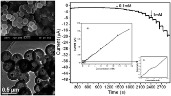
Yolk–shell nanostructures are a potential platform for the application of sensors and detection. In this paper, Ag@SiO2 yolk–shell nanoparticles (YSNs) were synthesized by a facile “two solvents” impregnation–reduction approach. XRD, SEM, TEM and N2 adsorption characterization results revealed that the resultant Ag@SiO2 YSNs possess distinctive structures, such as movable cores, perpendicular mesoporous channels, protective shells and hollow cavities. A nonenzymatic H2O2 sensor was constructed using Ag@SiO2 YSNs as sensing interface. A three-electrode system was used for the measurement. Electrochemical results indicate that the Ag@SiO2 YSNs modified electrode exhibits outstanding performance toward the H2O2 reduction, with a faster amperometric response, a lower detection limit (3.5 μM) and a wider linear range (0.1–15 mM) than that based on Ag@SiO2 composites, which was synthesized by a direct impregnation method.
Significant efforts have been made to combine noble metal nanoparticles and porous support for the controlled synthesis of a variety of nanostructures with unique morphologies and properties.9–15 Among different strategies, encapsulation of noble metal nanoparticles in hollow spheres, hollow silica/carbon sphere for example, to form a yolk–shell nanostructure has received considerable attention, which becomes another remarkable route to stabilize these nanoparticles.16,17 With the appealing structures of movable cores, interstitial hollow spaces between the movable core and shell sections, and the functional shells, yolk–shell nanoparticles (YSNs) have played critical roles in modern science and technology as promising candidates for emerging applications, such as nanoreactors,18–20 lithium-ion batteries,21,22 drug delivery,23,24 surface-enhanced Raman scattering,25,26 and sensors.27
Motivated by their promising prospects, many scientists have devoted to develop new synthetic approaches for these structures. Currently, the reported methods for YSNs include bottom-up or soft-templating methods,28–30 Ostwald ripening or galvanic replacement process,31,32 the Kirkendall effect based method,33,34 selective etching12,35–38 and ship-in-bottle approach.39–42 On this basic, a series of noble metal nanoparticles (i.e. Au,15 Ag,43,44 Pt,45 Fe,46 Ni47) have been introduced into the cavity of hollow spheres for the construction of YSNs. Targeting a yolk–shell nanostructure with Ag nanoparticles as cores, methods are conventionally employed such as hard-templating route,48 and a Stöber process.49 For example, Kang and co-workers reported the preparation of silver@silica@PMAA core double shell hybrid nanoparticles by distillation–precipitation polymerization with silver@silica core–shell NPs from the sol–gel reaction as hard template.48 Then, the Ag@PMAA YSNs were obtained by the removal of the silica shell by HF etching. The as-synthesized materials showed high catalytic activity for the degradation of p-nitrophenol. Although the hard template approach is successfully in producing YSNs, the procedure is a multiple step and complex process. Recently, a one-pot Stöber route was developed for the fabrication of Ag@carbon YSNs.49 In this method, AgBr–silica–RF polymer core double shell nanoparticles were prepared with AgNO3, TEOS, resorcinol, and formaldehyde as precursors. Then, Ag@C yolk–shell nanostructures are obtained by carbonization of RF and selective removal of the silica. The synthetic route reported here is expected to simplify the fabrication process of yolk–shell nanostructures, which usually entails multiple steps and previously synthesized metal nanoparticles and hard templates. However, synthesis of YSNs with Ag as cores by a simple and efficient way is barely reported and highly needed.
Herein, we describe a flexible and efficient route for the synthesis of Ag@SiO2 YSNs. The obtained Ag@SiO2 YSNs possess distinctive structures, such as dispersive Ag cores, perpendicular mesoporous channels, protective shells and hollow cavities. A nonenzymatic H2O2 sensor was conducted using Ag@SiO2 YSNs as sensing interface. Electrochemical results indicate that Ag@SiO2 YSNs modified electrode exhibits outstanding performance toward the H2O2 reduction, with a faster amperometric response, a lower detection limit (3.5 μM) and a wider linear range (0.1–15 mM) than that based on Ag@SiO2 composites, which was synthesized by a direct impregnation method.
![]() | ||
Fig. 1 (A) Small-angle and (B) wide-angle XRD patterns of (a) blank HMSS (b) Ag@SiO2-TS (c) Ag@SiO2-DI. |
The surface Ag composition of the as-prepared samples is also investigated by XPS (Fig. 2). The photoelectron peaks at 367.2 eV and 373.2 eV represent the binding energies of Ag 3d5/2 and 3d3/2, respectively. Noticeably, intensity of Ag 3d in Ag@SiO2-TS was much weaker than that of Ag@SiO2-DI, which can be contributed to the isolation of silica shells and the limited probe depth of XPS,51 further confirming that silver nanoparticles in Ag@SiO2-TS sample were mainly inside the cavity of HMSS.
The morphology and structure of the three samples were investigated by SEM and TEM. As can be seen in Fig. 3a, the blank HMSS have a smooth surface and uniform diameter of about 400 nm. After the introduction of silver, the Ag@SiO2 YSNs, fabricated by the sequential “two solvents” impregnation–reduction approach, retain the morphology and size of HMSS, with barely Ag particles on the outer shells (Fig. 3b). However, for the sample of Ag@SiO2-DI (Fig. 3c), many silver particles can been observed, sticking on the outer shell of HMSS or even aggregating out the spheres. Therefore, we have reasons to believe that almost all of the Ag was introduced into the shell of HMSS by sequential “two solvents” impregnation–reduction approach. TEM was performed to further investigate the mesostructure and interior construction of the as-synthesized materials. A noticeable contrast between the cavity and the shell is observed in Fig. 3d–f, which verify the hollow structure of HMSS. The cavity of HMSS provides the void for the introduction of Ag core and also provides the zone for the catalytic reaction. The HMSS have a shell thickness of 80 nm and an average diameter of about 400 nm (Fig. 3d), consistent with the results of SEM. The high-magnification TEM image (Fig. S1†) reveals that the shells of HMSS display uniform and ordered mesoporous channels, which are radially oriented to the sphere surface. This result means that the mesochannels of the hollow spheres are readily accessible, which make the molecules easily penetrate the shell and reach the Ag core. Fig. 3e displays the TEM image of Ag@SiO2-TS. Obviously, Ag cores, which are not located in center of the cavity, can be observed. This phenomenal deduces that the Ag cores are movable in the hollow space if it was filled with liquid,52,53 which could provide more active sites for catalytic reactions. Meanwhile, the spherical shape and mesostructure (inset in Fig. 3e) are kept during the impregnation and reduction process, and the yield of the product is very high (Fig. S2†). For comparison, in the TEM image of Ag@SiO2-DI (Fig. 3f), part of silver particles adhere to the outside surface of the shells or even appear aggregation out of the HMSS. The results obtained from TEM were consistent with the SEM and XRD characterization.
Fig. 4A shows the nitrogen adsorption/desorption isotherms of the as-synthesized materials and Table 1 (Table 1) lists their textural parameters for comparison. All the samples exhibit a type IV isotherm with a type H2 hysteresis loop, characteristic of mesoporous structure. According to the Brunauer–Emmett–Teller (BET) method, the specific surface areas of blank HMSS and Ag@SiO2-TS are 845.6 m2 g−1 and 769.4 m2 g−1, respectively. Therefore, after the incorporation of Ag cores, Ag@SiO2-TS still kept a high specific surface area. However, the BET surface area of Ag@SiO2-DI decrease more seriously than Ag@SiO2-TS, which is caused by the pores blocking of the Ag particles, sticking on the outer shells of HMSS. The pore size distribution derived from the adsorption branch for all samples are shown in Fig. 4B. The as-synthesized samples show a primary mesoporous size centered at 2.5 nm. Noticeably, after the sequential “two solvents” impregnation–reduction approach and direct impregnation processes, the Ag/SiO2 composites keep the same pore size and the mesoporous structure. Based on the morphology and structure characterizes, it can be confirmed that an Ag@SiO2 yolk–shell nanostructure with movable cores, perpendicular mesochannels, protective shells and hollow cavities has been successfully prepared via the sequential “two solvents” impregnation–reduction approach.
![]() | ||
Fig. 4 N2 adsorption/desorption isotherms (A) and pore size distributions (B) of (a) blank HMSS (b) Ag@SiO2-TS (c) Ag@SiO2-DI. |
Samples | SBET/m2 g−1 | Pore size/nm | Pore volume/cm3 g−1 |
---|---|---|---|
HMSS | 845 | 2.7 | 0.57 |
Ag@SiO2-TS | 769 | 2.7 | 0.54 |
Ag@SiO2-DI | 724 | 2.7 | 0.50 |
Several reports have shown that YSNs with metal cores in the hollow shells have high catalytic activity in different heterogeneous catalystic reactions.15–17,19 Meanwhile, the nanomaterials as nonenzymatic H2O2 sensors actually play the role of heterogeneous catalysts in the detection system.27 Therefore, there is reason to believe that YSNs can be a promising candidate for nonenzymatic H2O2 sensors.
To demonstrate the catalytic performance of Ag/SiO2-TS for H2O2 reduction, we designed an enzymeless H2O2 sensor by immobilization of the Ag@SiO2-TS on a bare GCE surface (Ag@SiO2-TS/GCE). Bare GCE and Ag@SiO2-DI/GCE were also constructed for comparison. Fig. 5 shows the cyclic voltammograms (CVs) of bare GCE, Ag@SiO2-TS/GCE and Ag@SiO2-DI/GCE in the presence of H2O2 (1 mM) in PBS at pH 6.8. No obvious response is observed for bare GCE. Meanwhile, the response toward H2O2 for Ag@SiO2-DI/GCE is remarkable (about 12.9 μA in intensity at −0.50 V), due to the existence of Ag. In contrast, the Ag@SiO2-TS/GCE exhibits a more remarkable reduction current peak, about 17.1 μA in intensity at −0.50 V. This improved catalysis could be contributed to the following factors. First, the mesoporous shell supplies many exposed hot spots to integrate with target molecules, which is critical to highly sensing performance because the heterogeneous reactions take place on the surface of solid phase.54,55 Meanwhile, the thin, mesoporous silica shell with a thickness of about 80 nm does not provide much resistance, and the rest porous system is open to the large hollow cavity. Then, the H2O2 molecules can easily penetrate through the mesoporous shells and reach the Ag cores.56 Second, the movable cores inside the void space provide more exposed active sites for the reaction between Ag nanoparticles and H2O2 molecules. Third, the catalytic reaction is confined within the void space, in which chemical reaction possesses may present vast differences because of the confining effect and change in microenvironments.57 The void space acts as a nanoreactor, which enriches the target molecules in the cavity and ensures the target molecules to be reacted as completely as possible. Moreover, it is found that the reduction peak current of Ag@SiO2-TS/GCE is increased with the gradual addition of H2O2 (Fig. 6), indicating the catalytic property of the modified electrode in the reduction of H2O2.
![]() | ||
Fig. 5 Cyclic voltammetries (CVs) of bare GCE, Ag@SiO2-TS/GCE and Ag@SiO2-DI/GCE in N2-saturated 0.2 M PBS at pH 6.8 in the presence of 1.0 mM H2O2. |
![]() | ||
Fig. 6 CVs of Ag@SiO2-TS/GCE in N2-saturated 0.2 M PBS at pH 6.8 in the presence of different concentration of H2O2. Potential scan rate: 50 mV s−1. |
Fig. 7 shows a typical current–time plot of the Ag@SiO2-TS/GCE in N2-saturated 0.2 M PBS buffer (pH: 6.8) on consecutive step change of H2O2 concentrations under optimized condition. When an aliquot of H2O2 was dropped into the stirring PBS solution, the reduction current rose steeply to reach a stable value. The Ag@SiO2-TS/GCE responded rapidly (achieve 95% of the steady state current within 5 s), indicating a fast amperometric response behavior. The inset (a) in Fig. 7 shows the calibration curve of the sensor, and the low concentration part of this line is shown in inset (b). The linear detection range and the detection limit were estimated to be from 0.1 mM to 15 mM (r = 0.999) and 3.5 μM at a signal-to-noise ratio of 3, indicating a promising property of the sensor. Several research groups have reported on the synthesis of Ag-based composites with other structures for enzyme-free H2O2 detection.58–60 By comparison, the detection performance of Ag@SiO2 YSNs was better than other Ag nanoparticles decorated structures, including Ag@TiO2 composites,58 Ag@SBA-15 (ref. 59) and Ag@graphene.60 The superiority of Ag@SiO2 YSNs may be contributed to the appealing properties of yolk–shell nanostructures in application of nanoreactors.
![]() | ||
Fig. 7 Typical steady-state response of the Ag@SiO2-TS/GCE to successive injection of H2O2 into the stirred N2-saturated 0.2 M PBS at pH 6.8 (applied potential: −0.5 V). Inset: the calibration curve. |
Footnote |
† Electronic supplementary information (ESI) available. See DOI: 10.1039/c4ra16061d |
This journal is © The Royal Society of Chemistry 2015 |