Effect of hydrothermal oxidation temperatures on tribological properties of carbon fabric/resin friction materials

Jie Fei*ab, Hong-Kun Wanga, He-Jun Lib, Jian-Feng Huanga, Li-Yun Caoa and Wei Luoa
aSchool of Materials Science and Engineering, Shaanxi University of Science and Technology, Xi'an, 710021, China. E-mail: lgfeijienwpu@163.com; Fax: +86 029 86168688; Tel: +86 134 88142894
bCarbon/Carbon Composite Research Center, The State Key Laboratory of Solidification Processing, Northwestern Polytechnical University, Xi'an, 710072, China

Received 9th December 2014 , Accepted 19th February 2015

First published on 19th February 2015


Abstract

Carbon fabric was treated by HNO3 under hydrothermal conditions. The oxygenated functional groups were supported by Fourier transform infrared-attenuated total reflectance spectroscopy. The hydrophilicity was supported by the contact angle instrument. The treated carbon fabric was then used to prepare carbon fabric/resin friction materials. The friction and wear behaviors of the carbon fabric/resin friction material were evaluated by a friction tester. Experimental results showed that the carbon fabric treated by hydrothermal oxidation led to changes in surface morphology of fibers and appearance of carbonyl groups, which effectively improved the bonding strength of carbon fabric and resin. Moreover, hydrothermal oxidation treatment from 100 °C to 120 °C was proved beneficial to tribological properties.

Introduction

Wet friction materials are widely used for transmission brake systems in various types of machinery and equipment, such as cars, trains, planes, ships, mining machinery, etc.1,2 They should maintain reasonably high and stable friction coefficients and low wear at wide ranges of temperature, pressure, speed and other operating conditions.3 In order to meet those requirements, carbon fabric/resin composites have emerged as one class of promising textile fabric constitutions, which shows extensive applications in industry.4,5 Fabrics are unique in their ability to provide mechanical strength in both longitudinal as well as transverse directions. Meanwhile it is easy to handle for compression molding of the composites. So as a class of important friction materials, carbon fabric/resin composites have been finding extensive applications in industry. But carbon fibers have low specific surface area, surface energy and surface hydrophobicity, which result in the weak adhesive strength, low shear strength and low bending strength between resin and carbon fabric.6,7

In order to improve the activity of the carbon fiber surface and increase the quantity of surface functional groups, many modified methods are put forward, such as electrochemical oxidation,8 plasma treatment,9,10 wet chemistry oxidation11,12 and gamma irradiation,13,14 etc. HNO3 is the most common reagent for the oxidation of carbon fibers, which can selectively remove amorphous carbon and at the same time generate abundant oxygenated groups at the exposed fibers surfaces.15 However, HNO3 treatment under boiling conditions is accompanied by severe degradation effects, including material's loss and selective removal of metallic nanotubes, tube shortening as well as the formation of structural defects and carbonaceous debris.16,17 So the introduction of hydrothermal method was carried out, which can not only improve oxidation temperature over 100 °C, but also has some advantages such as high efficiency and uniform corrosion. Recently, controlled surface functionalization was demonstrated by HNO3 hydrothermal oxidation on multiwall carbon nanotubes. The results indicated that hydrothermal oxidation competed well with the harsh boiling HNO3 treatment regarding the total amount of oxygen functionalities, while controlling amounts of oxygen functionalities on carbon nanotubes.18 This provides us a new point that HNO3 hydrothermal oxidation maybe developed as a controllable and mild functionalization method to modify the carbon fibers.

Previous research has shown that the oxidation treatment time and the concentration of HNO3 as well as oxidation temperature have great influence on the surface functionalization of carbon materials.19–22 However, the effect of hydrothermal treatment temperature on carbon fiber has not been well investigated. In this paper, carbon fabric was treated by a simple one-step HNO3 hydrothermal oxidation with different temperature to control surface functionalization of carbon fibers, which can be beneficial to the adhesion between resin and carbon fibers. And the influence of oxidation temperatures on morphology, structure and tribological properties of the friction materials were studied systematically in the present work.

Experimental details

Raw materials

Pitch-based carbon fabric (Jilin Jiyan high technology fiber Co. Ltd. China) was used as the main reinforcement. The nitrile butadiene rubber modified phenolic resin powder (Jinan Shengquan Hepworth Chemical Co. Ltd., Shandong, China) containing hexamethylenetetramine (a curing agent) was used as binder. HNO3 (65–68%) was used for the oxidation of carbon fabric.

Sample preparation

The carbon fabric was cleaned with acetone in an ultrasonic bath for 24 h and washed several times by distilled water. The cleaned carbon fabric was treated by HNO3 for 2 h under a hydrothermal condition with different temperatures. Then was rinsed in distilled water and dried at 80 °C in the oven. Thus the carbon fabric was immersed in resin using ethanol as solvent maintaining the resin content of 25%. And then it was dried at room temperature. The obtained preform sheets were molded for 10 min at 170 °C under 6.0 MPa via hot-press by vulcanizing machine. Thus, carbon fabric/resin friction materials were obtained. The as-prepared friction materials containing untreated and treated fibers at different hydrothermal temperatures of 100 °C, 120 °C and 140 °C were designated as H1, H2, H3 and H4, respectively.

Testing method and equipment

Carbon fiber and carbon fabric/resin friction materials surface were observed by scanning electron microscope (SEM, JEOL 6460). FTIR spectrum analysis of fibers was measured by Bruker Alpha type infrared spectrometer, using KBr compression method (scan range 400–3000 cm−1). Raman measurements were performed using a Renishaw inVia Reflex microscope with semiconductor laser, wavelength 532 nm, resolution 1 cm−1, scan range 500–3000 cm−1 to indicate fiber surface structure after modification. The water contact angle (CA) for liquids and fibers were measured with 10 μL water droplets and a contact angle instrument (DCA, DSA100, KRUSS, Germany) at room temperature. The friction and wear behaviors of the carbon fabric/resin friction materials were performed using a friction tester (CFT-I). Fig. 1 showed the schematic diagram of the test rig. Carbon fabric/resin friction materials (70 mm × 50 mm × 0.6 mm) were fixed on the guide of friction plate, which moved back and forth at a constant speed. Samples were slid against a couple plate (19 mm × 12 mm × 12 mm) for uniform contact.
image file: c4ra16056h-f1.tif
Fig. 1 Schematic diagram of the material surface friction tester.

The dynamic friction coefficient of the sample is calculated from eqn (1) as follows:

 
image file: c4ra16056h-t1.tif(1)
where μd is the dynamic friction coefficient, MD is the dynamic friction torque, P is the total pressure, Rcp is the sample width.

The wear volume of the sample is calculated from eqn (2) as follows:

 
image file: c4ra16056h-t2.tif(2)
where V is the wear volume, d is the wear track length, ΔYiM is the wear track depth, ΔXi is the wear track width, M is the surface baseline, n is the sampling point of wear track width. The wear test was carried out at reciprocating speed 500 rpm and contact pressure 160 N. For all samples, the wear test was repeated five times.

Results and discussion

Structure analysis of fibers

SEM images of the fibers were shown in Fig. 2. Grooves had different deep and shallow distributions on the fiber surface of the untreated sample (Fig. 2a), resulting from the production process of the wet spinning. The fiber surface was flat and smooth except the grooves. However, many small particles were dispersed on the surface of treated fibers (Fig. 2b–d). This was because the defect and edge carbon atom of fiber surface had been destroyed resulting in more and more asymmetric carbon atom in the hydrothermal oxidation condition. So the fiber surface was etched to expose the fiber core structure and a part of carbon atom became particle structure.23
image file: c4ra16056h-f2.tif
Fig. 2 SEM images of carbon fibers (a) H1; (b) H2; (c) H3; (d) H4.

In addition, the fiber surface was etched seriously with the increase of hydrothermal temperature. It indicated that the concentrated HNO3 damaged to serious roughness of fiber surface with the increase of hydrothermal temperature, which was mainly due to the enhancement of HNO3 oxidation ability caused by the increased treatment temperature and pressure in the reaction system. However, this phenomenon disappeared at 140 °C, showing that the surface of the fiber became very smooth without any groove. It may be due to the higher temperature would resulted in greater energy and increased nitro movement speed, which led to the oxidation reaction to entire surface of the carbon fiber, instead of oxidation reaction to the groove.

Raman spectra can distinguish different types of carbon structures because carbon materials exhibit two Raman-active modes. One is G-band in the vicinity of 1575 cm−1, represented the integrity of SP hybrid bond in graphite structure. The other is D-band in the vicinity of 1358 cm−1, which is resulted by its low degree of orientation, incomplete structure of graphite crystallite, much defect in the structure and many unsaturated carbon atoms. So the intensity ratio of ID/IG (R) is used to estimate the degree of graphitization of carbon fibers. The lower value of R means the higher degree of graphitization of carbon fibers.24 Fig. 3 was the Raman spectra of carbon fibers with different hydrothermal temperature. Both the G-band and D-band could be observed clearly. The samples showed increased intensity and decreased FWHM with the increase of hydrothermal temperature. R value decreased (Table 1) as the reaction temperature increased from 100 °C to 140 °C, which confirmed the HNO3 hydrothermal system promoted the degree of graphitization. This was because the increased hydrothermal temperature led to the seriously etched fiber surface and orderly structure of graphite,25 which was corresponded with the above SEM results.


image file: c4ra16056h-f3.tif
Fig. 3 The Raman spectra of carbon fibers.
Table 1 The Raman spectral parameters of carbon fibers
  D band G band R = ID/IG
Center FWHM Center FWHM
H1 1366.7 252.5 1586.9 99.3 2.91
H2 1361.5 226.7 1590.7 90.8 2.66
H3 1359.7 231.1 1589.1 91.3 2.63
H4 1357.5 216.8 1593.0 87.1 2.51


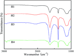
Fig. 4 showed the FTIR-ATR spectra of the untreated fiber and fiber with hydrothermal oxidation treatment. Bands at 1737 cm−1 were attributed to carbonyl groups. In addition, the absorption at 2800–3000 cm−1 was attributed to stretching vibrations of hydrocarbon groups,26 whereas bands at 1100–1193 cm−1 were attributed to C–O bonds.27 These groups became more and more obvious with the increase of hydrothermal temperature. Presence of carbonyl groups on carbon fiber surface would increase its surface activity and wettability with resin. These groups were responsible for the improvement in adhesion between resin and fabric.19


image file: c4ra16056h-f4.tif
Fig. 4 FTIR-ATR spectra of carbon fibers.

Wettability analysis of fibers

Fig. 5 showed the carbon fabric surface with different contact angles of the untreated fiber and fiber with different hydrothermal oxidation temperature. It could be seen that the water contact angles became smaller significantly with the increase of hydrothermal temperature, indicating that the surface hydrophilicity improved obviously after the HNO3 hydrothermal treatment. Its hydrophilicity enhancement could effectively improve the wettability and adhesion property of carbon fabric and resin matrix, thus improved the friction and wear performance of the friction materials.
image file: c4ra16056h-f5.tif
Fig. 5 Carbon fabric surface with different contact angles (a) H1; (b) H2; (c) H3; (d) H4.

Friction and wear properties studies

Fig. 6 showed the dynamic friction coefficient of the samples at different reaction temperature. Histogram represented the dynamic friction coefficient values which were the average values of 900 points tested under the conditions of 160 N loading pressure by CFT-I. The dynamic friction coefficient of the samples decreased with varying degrees hydrothermal treatment. This was because the carbon fabric wettability was improved, which could be fully combined with the resin matrix. Besides, lubricating oil penetrated into the friction material more easily, which improved the hydrodynamic lubrication and led to reduce the coefficient of friction.
image file: c4ra16056h-f6.tif
Fig. 6 Dynamic friction coefficient of carbon fabric/resin friction materials.

The wear volume of the samples decreased as the hydrothermal temperature increased, shown in Fig. 7, which confirmed this kind of treatment method could effectively improve the wear resistance of the friction material. This result was mainly due to the concentrated HNO3 etching effected on the surface of carbon fiber, leading to generate groove and functional group on the fiber surface, improving the bonding strength of carbon fabric and resin, thus enhancing the wear resistance. However, the wear volume of the friction material treated at 140 °C was higher than that of untreated friction material.


image file: c4ra16056h-f7.tif
Fig. 7 Wear volume of carbon fabric/resin friction materials.

Micrographs in Fig. 8 were worn surfaces of samples. The fracture phenomenon of carbon fiber (marked as 1) of H1 was serious. The main reason was that the surface of untreated carbon fabric was smooth with low surface energy, leading to low adhesive attraction between resin and carbon fiber, thus appearing the fracture phenomenon of carbon fiber, which reduced the wear resistance of friction materials. As the hydrothermal temperature increased, the worn surfaces became different with the samples H1. Part of the carbon fiber was binding on the resin matrix (marked as 2). However, a large number of carbon fibers were gradually polished by the couple plates showing the typical adhesive wear. Meanwhile, the combination of resin matrix and carbon fiber was good, indicating that 100 °C hydrothermal temperature could effectively improve the adhesion of resin matrix and carbon fiber as well as improve the self-lubricity wear resistant properties of the carbon fabric. Fiber fracture (marked as 1), resin loose phenomenon (marked as 3) and wear debris (marked as 4) were displayed in Fig. 8c, which illustrated the poor wear resistance properties compared with sample H2. However, as the hydrothermal temperature increased further to 140 °C, the fracture of carbon fiber was more serious, along with the serious abrasion of fiber, the hole left with fiber fracture and the different size of wear debris (marked as 4), which accelerated the damage to the friction material and showed the serious abrasive wear, resulting in the poor wear resistance. Although the adhesion of resin matrix and carbon fiber had improved, higher hydrothermal temperature could reduce the strength of carbon fiber, resulting in a large amount of carbon fiber fracture.


image file: c4ra16056h-f8.tif
Fig. 8 SEM images of the worn surfaces of samples with (1) fracture fiber; (2) broken fiber; (3) ploughed matrix; (4) wear debris (a) H1; (b) H2; (c) H3; (d) H4.

Conclusions

Carbon fabric treated by hydrothermal oxidation led to changes in surface morphology of fibers and appearance of carbonyl groups. Meanwhile the carbon fabric surface hydrophilicity improved obviously, which can effectively improve the bonding strength of carbon fabric and resin. Hydrothermal oxidation treatment at 100–120 °C to carbon fabric proved beneficial for abrasive wears performance. However, when the hydrothermal temperature increased to 140 °C, the carbon fiber strength decreased greatly, which could lead to serious abrasive wear and thereby reduce the wear-resisting property.

Acknowledgements

This work was supported by the National Natural Science Foundation of China (no. 51102196), the science and technology project of the young star of Shaanxi Province (2014KJXX-68), the Innovation Team Assistance Foundation of Shaanxi Province (2013KCT-06), the scientific research project of Shaanxi education department (14Jk1104), the fund of the State Key Laboratory of Solidification Processing in NWPU (SKLSP201316) and postgraduate innovative project of SUST (2014011). Their supports are gratefully acknowledged.

References

  1. P. Nyman, R. Mäki, R. Olsson and B. Ganemi, Wear, 2006, 261, 46 CrossRef CAS PubMed.
  2. M. Ingram, H. Spikes, J. Noles and R. Watts, Tribol. Int., 2010, 43, 815 CrossRef CAS PubMed.
  3. T. Jen and D. Nemecek, Int. J. Heat Mass Transfer, 2008, 51, 1757 CrossRef CAS PubMed.
  4. I. Srikanth, N. Padmavathi, S. Kumar, P. Ghosal, A. Kumar and C. Subrahmanyam, Compos. Sci. Technol., 2013, 80, 1 CrossRef CAS PubMed.
  5. B. Suresha and K. Kumar, Mater. Des., 2009, 30, 2056 CrossRef CAS PubMed.
  6. I. Choi and D. Lee, Composites, Part A, 2013, 48, 1 CrossRef CAS PubMed.
  7. M. Sharma, J. Bijwe and P. Mitschang, Wear, 2011, 271, 2261 CrossRef CAS PubMed.
  8. H. He, J. Wang, K. Li, J. Wang and J. Gu, Mater. Des., 2010, 31, 4631 CrossRef CAS PubMed.
  9. K. Ma, B. Wang, P. Chen and X. Zhou, Appl. Surf. Sci., 2011, 257, 3824 CrossRef CAS PubMed.
  10. M. Montes-Moran and R. Young, Carbon, 2002, 40, 845 CrossRef CAS.
  11. Q. Peng, Y. Li, X. He, H. Lv, P. Hu, Y. Shang, C. Wang, R. Wang, T. Sritharan and S. Du, Compos. Sci. Technol., 2013, 74, 37 CrossRef CAS PubMed.
  12. M. Sharma, S. Gao, E. Mäder, H. Sharma, L. Wei and J. Bijwe, Compos. Sci. Technol., 2014, 102, 35 CrossRef CAS PubMed.
  13. S. Tiwari, J. Bijwe and S. Panier, Wear, 2011, 271, 2184 CrossRef CAS PubMed.
  14. S. Tiwari, J. Bijwe and S. Panier, Wear, 2011, 270, 688 CrossRef CAS PubMed.
  15. Z. Tabti, R. Ruiz-Rosas, C. Quijada, D. Cazorla-Amoros and E. Morallon, ACS Appl. Mater. Interfaces, 2014, 6, 11682 CAS.
  16. C. Yang, J. Park, K. An, S. Lim, K. Seo, B. Kim, K. Park, S. Han, C. Park and Y. Lee, J. Phys. Chem. B, 2005, 109, 19242 CrossRef CAS PubMed.
  17. C. Bergeret, J. Cousseau, V. Fernandez, J. Mevellec and S. Lefrant, J. Phys. Chem. C, 2008, 112, 16411 CAS.
  18. R. Marques, B. Machado, J. Faria and A. Silva, Carbon, 2010, 48, 1515 CrossRef CAS PubMed.
  19. S. Tiwari, J. Bijwe and S. Panier, Wear, 2011, 271, 2252 CrossRef CAS PubMed.
  20. T. Saleh, Appl. Surf. Sci., 2011, 257, 7746 CrossRef CAS PubMed.
  21. X. Zhang, X. Pei and Q. Wang, eXPRESS Polym. Lett., 2007, 1, 318 CrossRef CAS.
  22. V. Likodimos, T. Steriotis, S. Papageorgiou, G. Romanos, R. Marques, R. Rocha, J. Faria, M. Pereira, J. Figueiredo, A. Silva and P. Falaras, Carbon, 2014, 69, 311 CrossRef CAS PubMed.
  23. Z. Wu, C. Pittman and S. Gardner, Carbon, 1995, 33, 597 CrossRef CAS.
  24. S. Sharma and S. Lakkad, Composites, Part A, 2011, 42, 8 CrossRef PubMed.
  25. K. Ho, A. Lee and A. Bismarck, Carbon, 2007, 45, 775 CrossRef CAS PubMed.
  26. E. Pamuła, M. Błażewicz, C. Paluszkiewicz and P. Dobrzyński, J. Mol. Struct., 2001, 596, 69 CrossRef.
  27. F. Severini, L. Formaro, M. Pegoraro and L. Posca, Carbon, 2002, 40, 735 CrossRef CAS.

This journal is © The Royal Society of Chemistry 2015
Click here to see how this site uses Cookies. View our privacy policy here.