Electrochemistry of Zn and co-reduction of Zn and Sm from LiCl–KCl melt

Yun Xueab, Zhi-Ping Zhoub, Yong-De Yan*ab, Mi-Lin Zhangb, Xing Lib, De-Bin Jib, Hao Tangb and Zhi-Jian Zhanga
aFundamental Science on Nuclear Safety and Simulation Technology Laboratory, Harbin Engineering University, Harbin 150001, P. R. China. E-mail: y5d2006@hrbeu.edu.cn; Fax: +86-451-82533026; Tel: +86-451-82569890
bKey Laboratory of Superlight Materials and Surface Technology, Ministry of Education, College of Materials Science and Chemical Engineering, Harbin Engineering University, Harbin 150001, P. R. China

Received 9th December 2014 , Accepted 20th February 2015

First published on 20th February 2015


Abstract

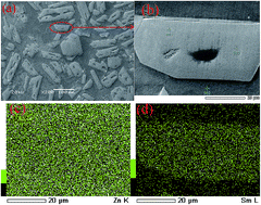
The electrochemical behavior of Zn(II) ions in LiCl–KCl and Sm(III) ions in LiCl–KCl–ZnCl2 melts on a Mo electrode at 773 K was studied by various electrochemical techniques. The results showed that the reduction of Zn(II) to Zn(0) consisted of a one-step process. The electrode reaction of LiCl–KCl–ZnCl2 solutions indicated that the under potential deposition of Sm on pre-deposited Zn electrode formed three kinds of Zn–Sm intermetallic compounds at electrode potentials around −1.57, −2.17 and −2.29 V. The electrochemical extraction of samarium was carried out in LiCl–KCl–ZnCl2 melts on a Mo electrode at 773 K by potentiostatic electrolysis (−2.3 V) for 40 h with an extraction efficiency of 99.87%. Zn–Sm bulk alloy was obtained by galvanostatic electrolysis. The microstructure and micro-zone chemical analysis of the Zn–Sm alloy were characterized by X-ray diffraction (XRD), scanning electron microscopy (SEM) and energy dispersive spectrometry (EDS).


Introduction

Nowadays, the traditional hydrometallurgical process is no longer available for extraction of lanthanides and actinides because of their low solubilities in an aqueous medium.1 Pyrochemical separation processes using molten salts have been proposed as an alternative approach for extracting lanthanides and actinides from fission products because of their high thermal resistance, high radiation resistance and high solubility of molten salts.2–4

Sm is a typical element of fission products. In principle, since the reduction potential of Sm(II) to Sm(0) is more negative than that of the solvent in the chloride system,5 it is impossible to extract Sm metal directly by electrolysis from molten salt chlorides. The only technique for extracting Sm metal is by a shift to a more positive potential on active electrodes.6,7

Some researchers have been interested in the extraction of lanthanides with variable valence. Castrillejo et al.8,9 have extracted Yb and Sm on a reactive Al cathode in LiCl–KCl melts. Massot and co-workers10,11 have also extracted Nd on reactive cathodes (Cu and Ni) in LiF–CaF2 melts at 920 °C. The extraction efficiencies were found to be more than 99.8% on both reactive electrodes. Smolenski et al.12 extracted Tm on a reactive Al cathode in NaCl–2CsCl melts. Massot et al.2 have investigated the Sm extraction in LiF–CaF2–AlF3 melts and calculated the extraction efficiency (99.4%). Massot and co-workers13 have also extracted Eu on a reactive cathode (Al and Cu) in LiF–CaF2 melts at 840 °C. Electrochemical extractions resulted in an extraction efficiency of about 92% for copper electrode, and 99.7% for co-reduction with aluminium ions.

The reduction potentials of lanthanides were more positive than that of Li+ on an inert electrode. To extract lanthanide completely from solvent, we need to minimize the ultimate concentration of lanthanide metal by controlling the electrode potential. The electroextraction (electrolytic separation) efficiency can be defined as

 
image file: c4ra16014b-t1.tif(1)
where αfinal and αinitial are the molarities of lanthanide after and before electroextraction. According to the equation of Nernst, the theoretical potential differences are decided by the initial and ultimate concentration of lanthanides we need to extract.
 
image file: c4ra16014b-t2.tif(2)
where R is the universal gas constant, T is the absolute temperature in K, n is the number of exchanged electrons, and F is Faraday’s constant (96[thin space (1/6-em)]485 C mol−1). From eqn (2), the reduction potential difference of lanthanide (it is the reduction potential difference of lanthanide and Li on an inert electrode in LiCl–KCl melts) depends on the electron transfer number and extraction efficiency, that is, the extraction efficiency is closely related to the reduction potential difference. The theoretical potential differences we need to achieve are listed in Table 1, when the electrolytic extraction efficiency η is in the range of 99–99.999%.14

Table 1 The relation between the theoretical potential difference and electrolytic extraction efficiency (T = 1100 K, n = 2–4)
99% 99.9% 99.99% 99.999%
ΔE (n = 2) 0.22 0.33 0.44 0.55
ΔE (n = 3) 0.15 0.22 0.29 0.36
ΔE (n = 4) 0.11 0.17 0.22 0.27


From Table 1 we see that we need to enlarge the precipitation potential difference between the lanthanide and metal ion in solvent to realize the complete electroextraction of lanthanide. Because the reduction potential of lanthanide is close to that of Li+, the complete extraction (separation) of lanthanide on an inert electrode is hard to achieve. Some lanthanide metals cannot, however, be obtained by electrolysis on an inert electrode (because the deposition potential of lanthanide metal is more negative than that of the solvent). Because the activity of lanthanide will decline on an activated cathode, electrodeposition of lanthanide on an active electrode will have a more positive deposition potential than on an inert electrode (that is, the depolarization effect).

Due to the increase of potential difference between lanthanide and Li on Al cathode, electrochemical extractions of lanthanides on Al cathode were extensively investigated. Massot and co-workers1 have extracted Nd on Al cathode in LiF–CaF2 melts at 860 °C, of which the extraction efficiency was more than 95%. They have also investigated Ce extraction on pre-deposited Al cathode in LiF–CaF2–AlF3 melts and calculated the extraction efficiency to be 99.5%.2 Yan et al.15 investigated the electrochemical extraction of Pr in the form of Al–Pr and Al–Li–Pr alloys from LiCl–KCl eutectic melts by potentiostatic and galvanostatic electrolysis at 500 °C. Zhang et al.16 studied the electrochemical extraction of thorium from LiCl–KCl molten salts by forming Al–Th alloys at 680 °C. Shi et al.17 carried out an electrochemical extraction of Gd from Gd2O3 in LiCl–KCl–AlCl3 molten salts. The electrochemical extraction of gadolinium was performed by co-reduction with Al3+ on the aluminum electrode with an extraction efficiency of 89.7% for potentiostatic electrolysis and 96.5% for galvanostatic electrolysis, respectively.

From the references above, most researchers have employed Al as a cathode to extract lanthanides. In this paper, a zinc cathode was applied to extract Sm. As we know, the deposition potential of zinc ion is more positive than that of aluminium ion in molten chlorides. The deposition potential of lanthanides on a zinc cathode will be more positive than that of lanthanides on an aluminium cathode, which means that the deposition potential difference between lanthanides on zinc cathode and Li will further increase. The deposition potential difference is larger, and the extraction efficiency is higher. Another factor to be considered is that Zn has a lower melting point (692 K) and boiling point (1180 K) in comparison with Al. Consequently, electrolysis can be carried out at a relatively low temperature. In addition, a lower boiling point facilitates the separation between Zn and Sm. Moriyama et al.18–20 evaluated the separation coefficient of actinides and lanthanides on a liquid zinc electrode in a LiF–BeF2 system, the results show that with liquid zinc as the cathode extraction of actinides and lanthanides from the molten chloride salts is feasible. Recently, our group has successfully extracted Tm on zinc cathode.21 Shi et al.22 investigated the co-reduction of Sm(III) and Zn(II) ions on the Mo electrode and the under potential deposition of Sm(III) ions on the liquid Zn electrode. They found that the recovery rate of Sm from the LiCl–KCl–SmCl3 (2 wt%) melt can reach to 94.5% by the electrolysis on the liquid Zn electrode. As far as we know, few studies on the electrochemical behavior of Zn(II) ion in molten LiCl–KCl have been reported in the literature.23,24 In this paper, the electrochemical behavior of Zn(II) ion on a molybdenum electrode in molten LiCl–KCl was investigated by various electrochemical techniques, and direct electrochemical extraction of samarium by co-reduction with zinc in LiCl–KCl molten salt was studied. The extraction efficiency of Sm was evaluated as well.

Experimental

Preparation and purification of the melts

The mixture of LiCl–KCl (63.7[thin space (1/6-em)]:[thin space (1/6-em)]36.3 mol%, analytical grade) was dried under vacuum for more than 48 h at 523 K to remove excess water. And then the mixture was melted in an alumina crucible placed in a quartz cell located in an electric furnace. The melts temperature was measured by a nickel–chromium thermocouple sheathed by an alumina tube. Metal ion impurities of the melts were removed by pre-electrolysis at −2.1 V (vs. Ag/AgCl) for 3 h. Zinc and samarium elements were introduced into the bath in the form of dehydrated ZnCl2 and SmCl3 powder. Since Ln ions are very sensitive to O2− ions, to avoid generating SmOCl or Sm2O3, HCl was bubbled through to purify the melts and then argon was bubbled to remove excess HCl.25

Electrochemical apparatus and electrodes

All electrochemical techniques were performed using an Autolab PGSTAT 302N electrochemical workstation (Metrohm Co., Ltd.) with a Nova 1.8 software package. The working electrodes were molybdenum wires (d = 1 mm, 99.99% purity), which were polished thoroughly using SiC paper, and then cleaned ultrasonically with ethanol prior to use. The counter electrodes were graphite rods (d = 6 mm, 99.99% purity). The active electrode surface area was determined by measuring the immersion depth of the electrode in the melts. The reference electrode was a silver wire (d = 1 mm) which was dipped into a Pyrex tube containing a solution of AgCl (1 wt%) in LiCl–KCl (63.7[thin space (1/6-em)]:[thin space (1/6-em)]36.3 mol%) melts. All potentials were referred to this Ag/AgCl couple.

Auxiliary techniques

The Zn–Sm alloy was prepared by galvanostatic electrolysis at 973 K. After electrolysis, the alloy sample was extracted from the melts and washed in hexane (99.8% purity) in an ultrasonic bath to remove salts. All operations were carried out under an argon atmosphere. The treated sample was stored in a glove box for analysis. The deposit was analyzed by XRD (X’Pert Pro; Philips Co., Ltd.) using Cu-Kα radiation at 40 kV and 40 mA. The specimen was mounted in thermosetting resins using a metallographic mounting press and then mechanically polished. Then, the microstructure and micro-zone chemical analysis were measured using SEM and EDS (JSM-6480A; JEOL Co., Ltd.). The concentrations of K(I), Li(I), Sm(III), and Zn(II) were analyzed using an inductively coupled plasma atomic emission spectrometer (ICP-AES, IRIS Intrepid II XSP, Thermo Elemental). The samples were taken from the clear supernatant fluid in the molten salt mixtures before and after electrolysis. After the clear supernatant fluid samples were solidified, each sample was dissolved in distilled water for analysis. The solution was diluted and analyzed using an ICP-AES. The contents of K(I), Li(I), Sm(III), and Zn(II) measured by ICP were converted to the masses of KCl, LiCl, ZnCl2, and SmCl3, and then the concentrations of zinc and samarium before and after electrolysis were calculated.

Results and discussion

Electrochemical behavior of Zn(II) in LiCl–KCl melts on a molybdenum electrode

Cyclic voltammetry. Cyclic voltammetry was performed on a molybdenum electrode in LiCl–KCl (63.7[thin space (1/6-em)]:[thin space (1/6-em)]36.3 mol%) melts (Fig. 1). Curve 1 represents the voltammogram before the addition of ZnCl2. Only one cathodic signal E is observed from approximately −2.37 V which is associated with the deposition of lithium, and the corresponding anodic signal E′ is related to the dissolution of lithium. Curve 2 shows the voltammogram with the addition of ZnCl2. In curve 2, prior to the cathodic signal E, another cathodic peak A (about −0.74 V) is seen and attributed to the reduction reaction of Zn(II) to Zn(0):
 
Zn(II) + 2e → Zn(0) (3)

image file: c4ra16014b-f1.tif
Fig. 1 Cyclic voltammograms of the LiCl–KCl melts before (curve 1) and after (curve 2) the adding of 9.5 × 10⁻⁵ mol cm−3 ZnCl2 on to a molybdenum electrode (S = 0.322 cm2) at 773 K. Scan rate: 0.1 V s−1.

In the positive-going scan, anodic peak A′ is attributed to the anodic oxidation process of the reaction. The increase of cathodic current from about −2.33 V is attributed to the underpotential deposition of Li on pre-deposited Zn to form Li–Zn alloy.

Fig. 2 exhibits the CV attained in LiCl–KCl–ZnCl2 (9.5 × 10⁻⁵ mol cm−3) melts on a molybdenum electrode at various scan rates at 773 K. From Fig. 2, ΔEPEP = |EpaEpc|) increases markedly with increasing sweep rate; ΔEP is larger than the value of 2.3RT/nF or 0.076 V for a two-electron reaction at 773 K. These results reveal that the deposition/dissolution reaction of Zn(II) ion is not completely reversible. There are two linear relationships between cathodic peak current (IP) and the square root of scan rate (v1/2), at low and high scan rates, respectively (Fig. 3). As a whole, the relationship between IP and v1/2 presents a transition from reversible to quasi-reversible and ultimately irreversible behavior. To further examine the reversibility of the electrode reactions, the dependencies of the cathodic and anodic peak potentials on the logarithm of the sweep rate are recorded (Fig. 4). Up to scan rates of 0.15 V s−1, the value of peak potential, EP, is consistent and independent of the sweep potential rate. Whereas for higher sweep rates, the values of the anodic and cathodic peak potentials shift slightly towards the positive and negative ones, respectively. These results display that the reduction of Zn(II) is quasi-reversible.26


image file: c4ra16014b-f2.tif
Fig. 2 Cyclic voltammograms for the reductions of Zn(II) to Zn(0) in the LiCl–KCl–ZnCl2 (9.5 × 10⁻⁵ mol cm−3) melts on a molybdenum electrode (S = 0.322 cm2) at 773 K.

image file: c4ra16014b-f3.tif
Fig. 3 Linear relationship of Zn(II) reduction peaks current vs. the square root of the potential scanning rate on a molybdenum electrode (S = 0.322 cm2) in the LiCl–KCl–ZnCl2 (9.5 × 10⁻⁵ mol cm−3) melts at 773 K.

image file: c4ra16014b-f4.tif
Fig. 4 Variation of the cathodic and anodic peak potentials with the logarithm of the sweep rate at 773 K.
Square wave voltammetry. Since square wave voltammetry is more sensitive and has a higher resolution than cyclic voltammetry,27–29 it was adopted to further examine the electrochemical behavior of Zn(II). Fig. 5 displays the square wave voltammogram of a solution of ZnCl2 at a step potential of 5 mV. One peak (peak A) at around 0.72 V is derived from the one-step reduction reaction of Zn(II) to Zn(0).
image file: c4ra16014b-f5.tif
Fig. 5 Square wave voltammogram of LiCl–KCl–ZnCl2 (9.5 × 10⁻⁵ mol cm−3) melts on a molybdenum electrode at 773 K. Pulse height: 100 mV; potential step: 5 mV; frequency: 20 Hz. Experimental (black) and corresponding fitting (red) curves.

The width of the half peak (W1/2) depends on the number of electrons transferred and on the temperature, and is calculated as follows:

 
image file: c4ra16014b-t3.tif(4)
where R, T, F, and n have the same meanings and units as described in eqn (2). To prove the reduction potential of Zn ions is −0.72 V, the number of electrons involved in this electrochemical step is determined by estimating the width of peak A at half of its height by eqn (4).28 The Gaussian fitting model is applied to process the curve (inset figure). Analysis of the obtained curves give the number of electrons (n = 2.1) involved in the electrochemical reduction reaction of peak A, which is approximately equal to 2. This value confirms that peak A originates from the reduction reaction of Zn. The square wave voltammogram results are in agreement with the cyclic voltammograms results.

Electrochemical behavior of Sm(III) in LiCl–KCl–ZnCl2 melts on a molybdenum electrode

Cyclic voltammetry. Cyclic voltammetry with different potential windows was performed at 773 K in the LiCl–KCl–SmCl3 (2.5 × 10⁻⁴ mol cm−3)–ZnCl2 (8.5 × 10⁻⁵ mol cm−3) system (Fig. 6). The scanning potential limits of the four cyclic voltammograms were −1.8, −2.2, −2.4 and −2.5 V, respectively. We can distinguish a corresponding situation between the oxidation and reduction peaks through different potential scanning limitations. In Fig. 6, two pairs of corresponding redox peaks A/A′ and B/B′ appear when the cathode limit reaches −1.8 V, excluding the A/A′ system at nearly −0.79/−0.59 V, corresponding to the deposition and subsequent reoxidation of zinc, cathodic peak B at roughly −1.56 V, which are attributed to the formation of Zn–Sm intermetallics; when scanning the limit to −2.2 V, a pair of corresponding reduction/oxidation peaks C/C′ occur, cathodic peak C at roughly −2.16 V, which are attributed to the formation of other Zn–Sm intermetallics; when scanning the limit to −2.4 V, in addition to the redox peaks A/A′, B/B′ and C/C′, redox peaks D/D′ are also detected, cathodic peak D at roughly −2.29 V, which are attributed to the formation of a third Zn–Sm intermetallics, the under potential deposition of samarium on the pre-deposited zinc film results in the formation of Zn–Sm alloys; when scanning the limit to −2.5 V, the last couple of E/E′ corresponding to the reduction and oxidation of Li metal is observed.
image file: c4ra16014b-f6.tif
Fig. 6 Cyclic voltammogram obtained at a molybdenum electrode (S = 0.322 cm2) at different cathodic limits in LiCl–KCl–SmCl3 (2.5 × 10⁻⁴ mol cm−3)–ZnCl2 (8.5 × 10⁻⁵ mol cm−3) system at 773 K. Scan rate: 0.1 V s−1.
Square wave voltammetry. Fig. 7 shows a square wave voltammogram of the LiCl–KCl–ZnCl2 (8.5 × 10⁻⁵ mol cm−3)–SmCl3 (2.5 × 10⁻⁴ mol cm−3) melts on a molybdenum electrode at a step potential of 5 mV and frequency of 10 Hz at 773 K. There are four apparent peaks at −0.76, −1.48, −2.09, −2.24 V corresponding to the formation of pure Zn metal and three different Zn–Sm alloys, respectively. The results of the square wave voltammogram are in agreement with the ones attained from the cyclic voltammograms (Fig. 6).
image file: c4ra16014b-f7.tif
Fig. 7 Square wave voltammogram of the LiCl–KCl–ZnCl2 (8.5 × 10⁻⁵ mol cm−3)–SmCl3 (2.5 × 10⁻⁴ mol cm−3) system on a molybdenum electrode (S = 0.322 cm2) at 773 K. Pulse height: 100 mV; potential step: 5 mV; frequency: 10 Hz.
Chronopotentiometry. Fig. 8 presents chronopotentiograms measured on a molybdenum electrode (S = 0.332 cm2) in LiCl–KCl–ZnCl2 (8.5 × 10⁻⁵ mol cm−3)–SmCl3 (2.5 × 10⁻⁴ mol cm−3) melts at various current intensities. The first plateau at −0.73 V marked 1, at a cathodic current lower than −20 mA, is associated with the reduction of Zn(II). Another three plateaus labeled 2, 3, and 4, observed at −1.52, −1.96, and −2.24 V, correspond to the formation of three kinds of Zn–Sm alloys. When the applied current is raised to −60 mA (−0.18 A cm−2), the potential plateau is approximately −2.39 V (plateau 5). At this current intensity, the codeposition of Zn and Sm occurs. The last plateau 5 is ascribed to the deposition of Li on the Mo electrode. It is clear that the potential regions for deposition of Zn and Sm are close to those observed in the cyclic voltammograms.
image file: c4ra16014b-f8.tif
Fig. 8 Chronopotentiograms obtained at different current intensities on a molybdenum electrode (S = 0.322 cm2) in the LiCl–KCl–ZnCl2 (8.5 × 10⁻⁵ mol cm−3)–SmCl3 (2.5 × 10⁻⁴ mol cm−3) melts at 773 K.
Open circuit chronopotentiometry. Fig. 9 shows a typical open-circuit chronopotentiogram obtained from LiCl–KCl–ZnCl2 (8.5 × 10⁻⁵ mol cm−3)–SmCl3 (2.5 × 10⁻⁴ mol cm−3) melts on a Mo electrode at 773 K. There are five plateaus at roughly: (1) −2.38 V, (2) −2.15 V, (3) −1.88 V, (4) −1.42 V, (5) −0.80 V.
image file: c4ra16014b-f9.tif
Fig. 9 Open-circuit potential transient curve for a Mo electrode (S = 0.322 cm2) after electrodepositing at −2.5 V vs. Ag/AgCl for 10 s in the LiCl–KCl–ZnCl2 (8.5 × 10⁻⁵ mol cm−3)–SmCl3 (2.5 × 10⁻⁴ mol cm−3) melts at 773 K.

Plateau 1 is the equilibrium potential plateau of Li(I)/Li. Plateau 5 is derived from the rest potential of the Zn film. Since Zn previously deposited on the molybdenum, the deposited Sm metal reacts with Zn and diffuses into the Zn substrate. This phenomenon results in the electrode potential gradually shifting to more positive values. During this process, a potential plateau is observed when the composition of the electrode surface is within a two-phase coexisting state.8,30,31 Therefore, plateaus 2, 3, and 4 are related to the formation of three different Zn–Sm intermetallic compounds.

Potentiostatic electrolysis and electrolytic extraction of samarium ions by co-reduction. The zinc firstly coats on to the molybdenum cathode to construct a zinc cathode. This conduces the deposition potential of samarium ions to move in a more positive direction by co-reduction with Zn(II) ions. This so-called “depolarization effect” allows the theoretical extraction efficiency of the lanthanides to be enhanced up to 100%.8 Based on the results of electrochemical studies, electrolytic extraction of samarium ions by co-reduction with Zn(II) ions was implemented via potentiostatic electrolysis in LiCl–KCl–ZnCl2 (1.3 × 10⁻⁴ mol cm−3)–SmCl3 (1.7 × 10⁻⁴ mol cm−3) melts on a molybdenum electrode. In light of the results of cyclic voltammograms and square wave voltammogram, we chose the potential of the co-reduction peak at about −2.3 V as the electrolysis potential. The extraction process is followed by drawing square wave voltammograms at different times to monitor the electroactive species content of molten salts. Furthermore, when measuring a new square wave voltammogram, a new molybdenum cathode should replace the last one to ensure the accuracy of the results.

Fig. 10 shows a series of square wave voltammograms measured in the extraction process. We observe that the current density decreases remarkably from the square wave voltammograms. The current density decreases more quickly at the initial stage than at the subsequent one in the electrolysis process. After 40 h electrolysis, the current density is close to zero.


image file: c4ra16014b-f10.tif
Fig. 10 A group of square wave voltammograms of the LiCl–KCl–ZnCl2 (1.3 × 10⁻⁴ mol cm−3)–SmCl3 (1.7 × 10⁻⁴ mol cm−3) melts at 773 K for different electrolysis durations on molybdenum electrodes (S = 0.322 cm2). Pulse height: 100 mV; potential step: 5 mV; frequency: 10 Hz.

To assess the extraction efficiency of the extraction process, the concentrations of Li, K, Zn and Sm elements in the melts after potentiostatic electrolysis for 40 h were measured by ICP. The weight percent of LiCl, KCl, ZnCl2 and SmCl3 of the melts after potentiostatic electrolysis were calculated to be 47.18%, 52.79%, 0.022% and 0.0019%, respectively. Consequently, the extraction efficiency is evaluated by eqn (1). Where αinitial is the initial concentration of Sm(III) in the melts, and αfinal is the final concentration of Sm(III) in the melts. The extraction efficiency of the samarium ion is computed to be 99.87%. Combined with the initial concentrations of ZnCl2 and SmCl3 and the extraction efficiency, Sm should be extracted in the form of Sm–Zn alloy and Sm solid solution after potentiostatic electrolysis for 40 h since no alloy with Sm composition higher than Zn exists in Sm–Zn binary alloy systems.

Galvanostatic electrolysis and characterization of the deposits. Alloys prepared at a low temperature are always residue-shaped and high temperature is beneficial for the aggregation of alloys: therefore, galvanostatic electrolysis (−1.95 A) was executed for 2.5 h in LiCl–KCl–ZnCl2 (1.3 × 10⁻³ mol cm−3)–SmCl3 (1.3 × 10⁻⁴ mol cm−3) melts on a molybdenum electrode at 973 K. Fig. 11 shows the X-ray diffraction patterns of an alloy sample obtained by galvanostatic electrolysis from the LiCl–KCl–ZnCl2 (1.3 × 10⁻³ mol cm−3)–SmCl3 (1.3 × 10⁻⁴ mol cm−3) melts. The XRD pattern of the sample shows the formation of Sm2Zn17, LiZn and Zn phases. With the extension of electrolysis time, Sm could be extracted in the form of Sm–Zn alloy and Sm solid solution.
image file: c4ra16014b-f11.tif
Fig. 11 XRD patterns of deposit obtained by galvanostatic electrolysis (−1.95 A) for 2.5 h on a molybdenum electrode (S = 0.322 cm2) in the LiCl–KCl–ZnCl2 (1.3 × 10⁻³ mol cm−3)–SmCl3 (1.3 × 10⁻⁴ mol cm−3) melts at 973 K.

To inspect the distribution of Zn and Sm elements in the alloy obtained by galvanostatic electrolysis from the LiCl–KCl–ZnCl2 (1.3 × 10⁻³ mol cm−3)–SmCl3 (1.3 × 10⁻⁴ mol cm−3) melts, SEM and EDS mapping analysis of the alloy sample were performed (Fig. 12). From the SEM image, a large number of small lumpy precipitates are seen on the surface of the alloy. One random block was taken, magnified (from the red circle), and examined with EDS mapping analysis. From the mapping analysis of elements, we find that Sm element mainly distributes in the white zone in the SEM photograph of the alloy. To further investigate the distribution of Sm, EDS quantitative analysis was carried out. The EDS results of the points marked 1, 2 and 3 taken from the white zone and black zone show that the deposit is made up of elements Zn and Sm. At the same time, the results of the EDS demonstrate that the white zone dissolves more Sm (39.01 mass% at point 3) than the black zone (0.87 mass% at point 2).


image file: c4ra16014b-f12.tif
Fig. 12 SEM and EDS analysis of the alloy sample obtained by galvanostatic electrolysis (−1.95 A) for 2.5 h on a Mo electrode (S = 0.322 cm2) in the LiCl–KCl–ZnCl2 (1.3 × 10⁻³ mol cm−3)–SmCl3 (1.3 × 10⁻⁴ mol cm−3) melt at 973 K. (a) The SEM of the alloy; (b) the SEM of the alloy (taken from the red circle); (c) the Zn element distribution; (d) the Sm element distribution; (e) EDS analysis.

Conclusion

The electrochemical behavior of Zn(II) on a molybdenum electrode in molten LiCl–KCl–ZnCl2 at 773 K was investigated by various electrochemical techniques. We proved that Zn(II) was reduced to Zn metal by a one-step process, that is, Zn(II) + 2e → Zn(0). The electrochemical reductions of Zn(II) to Zn(0) were found to be quasi-reversible. The extraction of Sm(III) ion by co-reduction with Zn(II) ion in LiCl–KCl–ZnCl2–SmCl3 melts on an inert electrode at 773 K was found to be feasible. The extraction efficiency of Sm(III) was estimated to be 99.87% after potentiostatic electrolysis for 40 h. This co-reduction process can indeed be used for other electrochemical systems for extraction of lanthanides and alloy preparation. According to the co-reduction mechanism, Zn–Sm alloy with Sm2Zn17 phase was obtained directly via co-reduction of Zn, Sm on an inert electrode in molten LiCl–KCl–ZnCl2–SmCl3 melts.

Acknowledgements

The work was financially supported by the China Scholarship Council, the National Natural Science Foundation of China (21103033, 21101040, and 91226201), the Fundamental Research funds for the Central Universities (HEUCF201403001), the Foundation for University Key Teacher of Heilongjiang Province of China and Harbin Engineering University (1253G016 and HEUCFQ1415), and the Special Foundation Heilongjiang Postdoctoral Science Foundation (LBH-TZ0411). The authors are particularly grateful to Prof. Thomas Hartmann and Prof. Yi-Tung Chen (Department of Mechanical Engineering, University of Nevada Las Vegas, USA) for kindly discussing various parts of the manuscript.

References

  1. M. Gibilaro, L. Massot, P. Chamelot and P. Taxil, J. Nucl. Mater., 2008, 382, 39–45 CrossRef CAS PubMed.
  2. M. Gibilaro, L. Massot, P. Chamelot and P. Taxil, Electrochim. Acta, 2009, 54, 5300–5306 CrossRef CAS PubMed.
  3. K. C. Marsden and B. Pesic, J. Electrochem. Soc., 2011, 158, 111–120 CrossRef PubMed.
  4. C. Y. Han, M. Ozawa and M. Saito, Sci. China: Chem., 2012, 55, 1746–1751 CrossRef CAS.
  5. K. E. Johnson and J. R. Mackenzie, J. Electrochem. Soc., 1969, 116, 1697–1730 CrossRef CAS PubMed.
  6. T. Iida, T. Nohira and Y. Ito, Electrochim. Acta, 2001, 46, 2537–2544 CrossRef CAS.
  7. T. Iida, T. Nohira and Y. Ito, Electrochim. Acta, 2003, 48, 2517–2521 CrossRef CAS.
  8. Y. Castrillejo, P. Fernández, J. Medina, M. Vega and E. Barrado, Electroanalysis, 2011, 23, 222–236 CrossRef CAS.
  9. Y. Castrillejo, P. Fernández, J. Medina, P. Hernández and E. Barrado, Electrochim. Acta, 2011, 56, 8638–8644 CrossRef CAS PubMed.
  10. C. Nourry, L. Massot, P. Chamelot and P. Taxil, J. Appl. Electrochem., 2009, 39, 2359–2367 CrossRef CAS PubMed.
  11. P. Taxil, L. Massot, C. Nourry, M. Gibilaro, P. Chamelot and L. Cassayre, J. Fluorine Chem., 2009, 130, 94–101 CrossRef CAS PubMed.
  12. V. Smolenski and A. Novoselova, Electrochim. Acta, 2012, 63, 179–184 CrossRef CAS PubMed.
  13. M. Gibilaro, L. Massot, P. Chamelot, L. Cassayre and P. Taxil, Electrochim. Acta, 2009, 55, 281–287 CrossRef CAS PubMed.
  14. P. Chamelot, L. Massot, C. Hamel, C. Nourry and P. Taxil, J. Nucl. Mater., 2007, 360, 64–74 CrossRef CAS PubMed.
  15. H. Tang, Y. D. Yan, M. L. Zhang, X. Li, Y. Huang, Y. L. Xu and Y. Xue, Electrochim. Acta, 2013, 88, 457–462 CrossRef CAS PubMed.
  16. Y. L. Liu, Y. D. Yan, W. Han, M. L. Zhang, L. Y. Yuan, K. Liu, G. A. Ye, H. He, Z. F. Chai and W. Q. Shi, RSC Adv., 2013, 3, 23539–23547 RSC.
  17. K. Liu, Y. L. Liu, L. Y. Yuan, X. L. Zhao, Z. F. Chai and W. Q. Shi, Electrochim. Acta, 2013, 109, 732–740 CrossRef CAS PubMed.
  18. H. Moriyama, T. Seshimo, K. Moritani, Y. Ito and T. Mitsugashira, J. Alloys Compd., 1994, 213, 354–359 CrossRef.
  19. H. Moriyama, H. Yamana, S. Nishikawa, Y. Miyashita, K. Moritani and T. Mitsugashira, J. Nucl. Mater., 1997, 247, 197–202 CrossRef CAS.
  20. H. Moriyama, H. Yamana, S. Nishikawa, S. Shibata, N. Wakayama, Y. Miyashita, K. Moritani and T. Mitsugashira, J. Alloys Compd., 1998, 271, 587–591 CrossRef.
  21. X. Li, Y. D. Yan, M. L. Zhang, Y. Xue, H. Tang, Z. P. Zhou, X. N. Yang and Z. J. Zhang, J. Radioanal. Nucl. Chem., 2014, 299, 657–664 CrossRef CAS.
  22. Y. L. Liu, L. Y. Yuan, G. A. Ye, M. L. Zhang, H. He, H. B. Tang and W. Q. Shi, Electrochim. Acta, 2014, 120, 369–378 CrossRef CAS PubMed.
  23. H. A. Laitinen and H. C. Gaur, J. Electrochem. Soc., 1957, 104, 730–737 CrossRef CAS PubMed.
  24. H. A. Laitinen, R. P. Tischer and D. K. Roe, J. Electrochem. Soc., 1960, 107, 546–555 CrossRef CAS PubMed.
  25. M. Gibilaro, L. Massot, P. Chamelot and P. Taxil, J. Alloys Compd., 2009, 471, 412–420 CrossRef CAS PubMed.
  26. Y. Castrillejo, M. R. Bermejo, P. D. Arocas, A. M. Martínez and E. Barrado, J. Electroanal. Chem., 2005, 579, 343–358 CrossRef CAS PubMed.
  27. S. Q. Jiao and H. M. Zhu, J. Hazard. Mater., 2011, 189, 821–826 CrossRef CAS PubMed.
  28. P. Chamelot, B. Lafage and P. Taxil, Electrochim. Acta, 1997, 43, 607–616 CrossRef.
  29. J. De Strycker, P. Westbroek and E. Temmerman, Electrochem. Commun., 2002, 4, 41–46 CrossRef CAS.
  30. T. Nohira, H. Kambara, K. Amezawa and Y. Ito, J. Electrochem. Soc., 2005, 152, 183–189 CrossRef PubMed.
  31. H. Konishi, T. Nishikiori, T. Nohira and Y. Ito, Electrochim. Acta, 2003, 48, 1403–1408 CrossRef CAS.

This journal is © The Royal Society of Chemistry 2015
Click here to see how this site uses Cookies. View our privacy policy here.