DOI:
10.1039/C4RA15847D
(Paper)
RSC Adv., 2015,
5, 6019-6026
A novel Z-scheme WO3/CdWO4 photocatalyst with enhanced visible-light photocatalytic activity for the degradation of organic pollutants†
Received
5th December 2014
, Accepted 11th December 2014
First published on 15th December 2014
Abstract
A novel Z-scheme WO3/CdWO4 photocatalyst has been fabricated with sheet-like tungsten trioxide (WO3) hybridized by rod-like cadmium tungstate (CdWO4) via a hydrothermal and chemisorption method. The as-synthesized WO3/CdWO4 photocatalyst exhibited enhanced photocatalytic efficiency for the degradation of different organic dyes under visible light irradiation. It was found that the photocatalytic performance of the composite WO3/CdWO4 was much higher than that of either WO3 or CdWO4 for the degradation of each organic dye. The highest activity of the composite was recorded for the degradation of MB which was about 7 times greater than pure CdWO4 and 2.3 times that of pure WO3. The enhanced performance of the photocatalyst was mainly attributed to the increased surface area and introduction of WO3 into the composite sample, which can induce higher adsorption activity for organic dyes and increased electron–hole separation at the interface between two semiconductors by establishing an inner electric field.
Introduction
Since the discovery of photocatalytic splitting of water by TiO2 in 1972,1 photocatalysis has become one of the promising water decontamination techniques, in which a semiconductor material is used as a catalyst to degrade organic dyes or environmental pollutants. Unlike the traditional methods of purification, photocatalysis technology has received significant attention because of its effective removal of structurally stable refractory pollutants and excellent degradation efficiency.2 However, it has been noticed the practical applications of single-phase photocatalysts are usually restricted due to limited visible-light response and high recombination rate of photoexcited electron–hole pairs which play important role in photocatalytic reaction.3 Hence, exploring the novel semiconductors with excellent photocatalytic activity and irreplaceable merits for the decomposition of organic pollutants present in water or air has become a research hotspot nowadays, which is necessary for resolving many problems of mankind regarding the environmental pollution.4
To design the efficient photocatalysts is a critical issue that involves light absorption, transfer/separation of photogenerated charge carriers and the subsequent catalysis, etc. During the last few years, various methods such as doping,5 coupling plasmon resonance,6 size and crystal facet of semiconductors and controlling morphology7,8 have been adopted to enhance the photocatalytic performance of photocatalysts. Among these strategies, the construction of heterostructures has been proved more effective for improving photocatalytic efficiency. Therefore, coupling of two kinds of semiconductors with visible light response has recently become very famous as a Z-scheme process.9 This scheme provides some advantages: (1) efficient charge separation, (2) simultaneously high reduction power and deep oxidation power even with visible light of less energy, and (3) different kinds of photocatalysts can be developed.3,10 Further, the synergistic effect of heterojunctions can excellently slow down the recombination and speed up the separation rate of photogenerated electron–hole pairs which results in the enhancement of photocatalytic activity.11 Thus, Z-scheme/heterojunction photocatalysts12 have attracted much attention among all other photocatalysts. In the recent years, it has been observed that W-based metal oxides (tungstates) exhibit very good physicochemical properties because of their self-trapped excitons13 and also it has been confirmed that the tungstate materials show good photocatalytic activity for degradation of contaminants.14 CdWO4, a layered compound crystallizing in a monoclinic wolframite structure is considered to be an attractive material because of its optical, chemical and structural properties.13,15 It has wide band gap larger than the conventional photocatalyst TiO2 (ref. 16) thus it seems to indicate limited photo-absorption, however, it could be still excited by light energy higher than its band gap to induce energy-rich electron–hole pairs that consequently degrade the toxic pollutants into nontoxic CO2 and H2O components during the photocatalytic process.17 But the fast recombination ratios of photogenerated charge carriers and poor response to visible light damage the practical applications of CdWO4. Therefore, significant efforts have been taken into account to overcome such problems. The photocatalytic efficiency of Eu3+-doped CdWO4 was found higher than that of undoped sample for degradation of MO.18 Similarly, the photocatalytic H2 production rate of CdS-modified CdWO4 was found about 34 times higher than the pure CdWO4.19 Very recently, Xu et al.20 fabricated CdWO4-deposited reduced graphene oxide and studied its enhanced photocatalytic properties by degrading methylene blue under UV light; the results were much higher than single CdWO4. Generally, the photocatalytic performance of the semiconductors can be enhanced by increasing the separation efficiency of photogenerated charge carriers. Therefore, the combination of two photocatalysts would be proved an ideal system in extending the absorption spectra to visible light region to attain a high separation efficiency of photogenerated charge carriers. However, to date, there is no report on the coupling of WO3 with CdWO4 and effect of this coupling on the photocatalytic efficiency of resulting photocatalyst.
In this article, we fabricated a novel Z-scheme/heterostructured WO3/CdWO4 photocatalyst for the first time by simple mixing and heating method and studied its enhanced photocatalytic activities for the degradation of organic pollutants under visible-light irradiation. We have mixed WO3, a small band gap nontoxic transition metal oxide having high oxidation power, ideal visible light response and good stability21 with the wide band gap CdWO4. To the best of our knowledge, this is the first report on the combination of WO3 with CdWO4 for the evaluation of enhanced photocatalytic properties under visible light irradiation. In the end, the synergistic effect between CdWO4 and WO3 and possible mechanisms for enhanced photocatalytic performance has been discussed as well.
Experimental
Fabrication of WO3/CdWO4 photocatalyst
All the chemicals used for synthesis in this work, were reagent grade and were commercially available and were used without further purification. First the rods-like CdWO4 was synthesized by hydrothermal method. Typically 5 mmol of Na2WO4·2H2O and 5 mmol of Cd(NO3)2·4H2O were dissolved in 15 mL distilled water and stirred for 30 min, during the stirring aqueous ammonia was added dropwise to the solution to attain a pH value of 9.30. The clear white solution was taken into stainless steel autoclave and heated at 180 °C for 24 hours. After washing several times with absolute ethanol and deionized water, a white colour powder was obtained. WO3 sheets-like structure was synthesized by CVD method: 0.5 g tungsten powder was taken into alumina ceramic boat and placed in the furnace. It was heated at 600 °C with ramp rate 10 °C min−1 in air flow for 3 hours. The tube was then allowed to cool at room temperature and yellow colour powder was collected. WO3/CdWO4 photocatalyst was fabricated as follows; appropriate amounts of WO3 and CdWO4 (1![[thin space (1/6-em)]](https://www.rsc.org/images/entities/char_2009.gif) :1) were dispersed in 10 mL of ethanol in separate glass beakers and sonificated for 1 hour. The dispersed solutions were then mixed and magnetically stirred for 1 hour and then heated at 80 °C for 12 hours. The obtained powder was then calcined at 550 °C for 2 hours. The final product was preserved for characterizations and measurements.
:1) were dispersed in 10 mL of ethanol in separate glass beakers and sonificated for 1 hour. The dispersed solutions were then mixed and magnetically stirred for 1 hour and then heated at 80 °C for 12 hours. The obtained powder was then calcined at 550 °C for 2 hours. The final product was preserved for characterizations and measurements.
The phase characterization of as-prepared photocatalyst WO3/CdWO4 was done by X-ray diffraction (XRD; Philips X'Pert Pro MPD), using a Cu Kα radiation source (λ = 0.15418 nm) with 2θ from 10° to 80°. The field emission scanning electron microscopy (FESEM) and transmission electron microscope (TEM, H-600-II, and Hitachi) high resolution transmission electron microscopy (HRTEM) and selected area electron diffraction (SAED) pattern were employed to characterize the morphology and composition of the as-prepared sample. The chemical composition of the samples was determined by energy dispersive X-ray (EDX) analysis (Hitachi S-3500). Fourier transform infrared (FTIR) spectra of samples were measured by using Nicolet Avatar-370 spectrometer. The Brunauer–Emmett–Teller (BET) specific surface areas of the sample materials were measured in a Micromeritics nitrogen adsorption instrument HYA2010-C2 (Beijing ZhongKe Hui Yu Technology Co., Ltd). The optical absorption and energy band gap spectra of the samples were examined by UV-VIS-NIR (Hitachi-4100) spectrophotometer whereas the photoluminescence (PL) spectra were measured with Hitachi FL-4500 fluorescence spectrometer at room temperature.
Measurements of the photocatalytic activity
In order to evaluate the photocatalytic activity of the fabricated photocatalyst, an aqueous solution of each dye MO, RhB and MB (100 mL, 10 mg L−1) was prepared in glass beaker and then 100 mg of the photocatalyst were added in this solution. The glass beaker was covered and kept in darkness under constant magnetic stirring for 30 minutes to obtain adsorption–desorption equilibrium between the photocatalysts and dye solution, and then this solution was exposed to 500 W xenon lamp which was used as a visible light source. After 10 min time intervals, 5 mL of solution was taken and centrifuged to remove the photocatalyst particles before measuring the UV absorption spectra. The filtrates were then analysed by measuring the variations in absorption band maximum (MO 508 nm, RhB 553 nm and MB 663 nm) using a UV-VIS-NIR (Hitachi U-4100) spectrophotometer. To examine the photostability of the photocatalyst, the same materials were centrifuged and dried and used again for degradation by repeating the above mentioned steps for second and third time.
Results and discussion
Phase structures and morphology
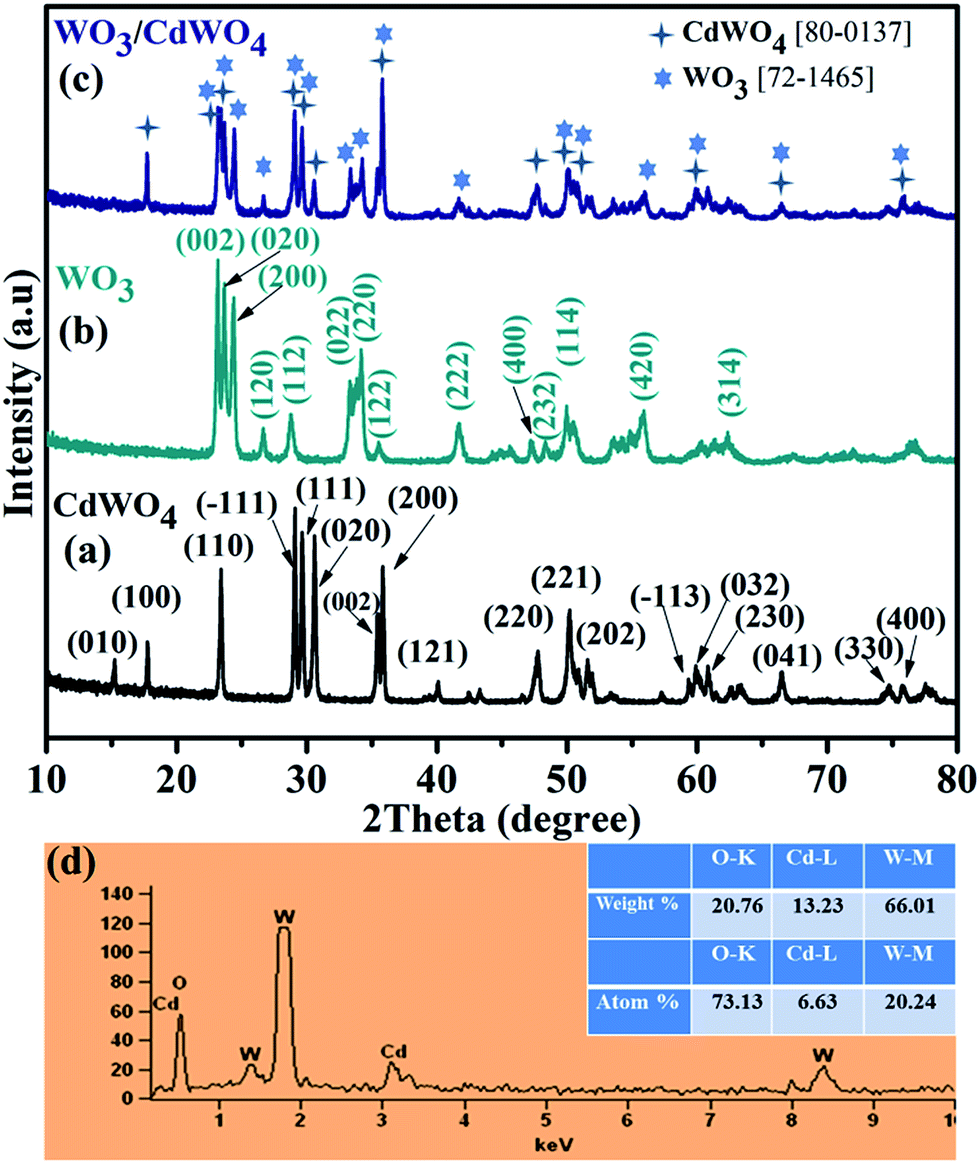
X-ray diffraction (XRD) analysis was employed to characterize the crystal structure and to identify the phase of the as-synthesized photocatalyst WO3/CdWO4, as well as pure CdWO4 and WO3 as shown in Fig. 1. Fig. 1(a) shows the typical XRD pattern of CdWO4 microrods, the well-defined diffraction peaks with relative diffraction intensities can be clearly indexed to a pure monoclinic phase of cadmium tungstate (JCPDS Card no. 87-1114, with lattice constants a = 5.0289 Å, b = 5.8596 Å, c = 5.0715 Å and α = γ = 90°, β = 91.5190°) with distinctive peaks centred at 23.31°, 29.02°, 29.58°, 30.49°, 35.34°, 35.76° and 47.7° match well with (110), (−111), (111), (020), (002), (200) and (220) respectively. Fig. 1(b) presents the XRD of the WO3 sheets-like structure. All the diffraction peaks are well matched with the orthorhombic crystalline phase of WO3, which was in good agreement with the standard card (JCPDS Card no. 89-4479, with lattice parameters a = 7.3612 Å, b = 7.5739 Å, c = 7.7620 Å and α = β = γ = 90°) with distinctive peaks at 23.028°, 23.52°, 24.25°, 33.14° and 34.12° corresponding to (002), (020), (200), (022) and (220) planes respectively. Fig. 1(c) represents the XRD pattern of the as-prepared composite WO3/CdWO4. It can be noted that the composite sample contains the peaks of both materials with slightly different positions that could be expected after mixing and heating process. The composite sample is purely composed of CdWO4 and WO3 that can be further confirmed from the EDX spectrum as shown in Fig. 1(d). The EDX spectrum shows that the as-synthesized product contains only W, O and Cd elements and no other element or impurity found in the fabricated WO3/CdWO4 photocatalyst.
 |
| | Fig. 1 XRD patterns of (a) CdWO4, (b) WO3, and (c) WO3/CdWO4 photocatalyst (d) the energy dispersive X-ray (EDX) spectrum of WO3/CdWO4 photocatalyst. | |
The morphology and structure of the as-synthesized materials were characterizes by SEM as shown in Fig. 2. The Fig. 2(a) represents the typical SEM image of WO3 microsheets that are uniformly distributed over the entire surface at different orientations. Fig. 2(b) shows the rods-like structure of CdWO4. It can be seen that the rods are assembled in such a way that it presents a view more like to the leaf of a palm tree. Fig. 2(c and d) depicts the SEM image of the as-prepared WO3/CdWO4 photocatalyst at different magnifications. It can noted that WO3 microsheets were shrunk when combined with CdWO4 rods and some of them attached/stuck with the rods as can be seen in a close view in Fig. 2(d). Although by mixing the two materials, there is no big change observed in their structures but this mixing plays an obvious effect on the optical and photocatalytic properties of the obtained product/photocatalyst.
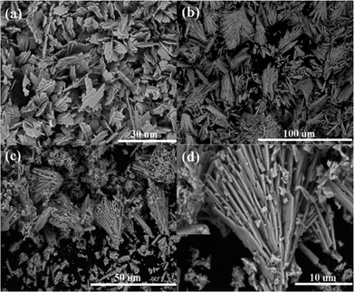 |
| | Fig. 2 (a) SEM image of sheets-like WO3, (b) SEM image of rods-like CdWO4, and (c and d) SEM images of WO3/CdWO4 photocatalyst at different magnifications. | |
Fig. 3(a–d) shows the FESEM images of the as-synthesized WO3/CdWO4 photocatalyst at different magnifications. Here, it can be clearly noticed that microsheets of WO3 are shrunken and converted into bunches and are attached/stuck with the CdWO4 rods.
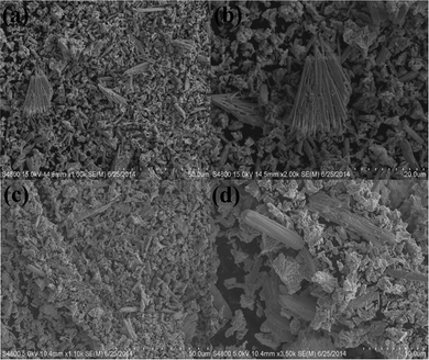 |
| | Fig. 3 (a–d) FESEM images of the as-prepared WO3/CdWO4 photocatalyst at different magnifications. | |
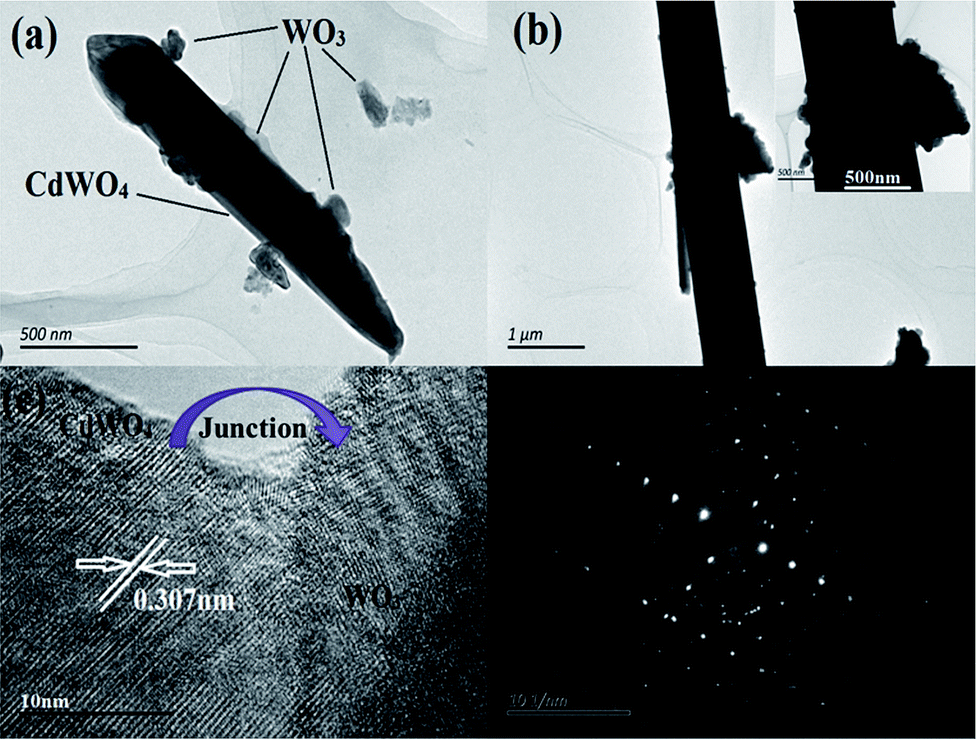
Fig. 4(a and b) represents the TEM characterization of the composite sample at different magnifications. The rods-like shape of CdWO4 can be clearly seen here and we can also note in Fig. 4(a and b) that there are sheets of WO3 attached with this rod. Fig. 4(c) shows the HRTEM image of the as-synthesized WO3/CdWO4 photocatalyst. It can be clearly noticed that there are two kinds of lattice fringes of two different materials which confirm the interfaces between WO3 and CdWO4 (see also Fig. S1 ESI†). From the HRTEM image (Fig. 4c), the spacing between two adjacent lattice fringes was found to be 0.307 nm that corresponds to the (−111) plane of CdWO4. Fig. 4(d) represents the SAED image of the sample.
 |
| | Fig. 4 (a and b) TEM images at different magnifications, (c) HTEM image, and (d) SAED image of WO3/CdWO4 photocatalyst respectively. | |
FTIR analysis and BET surface area measurements
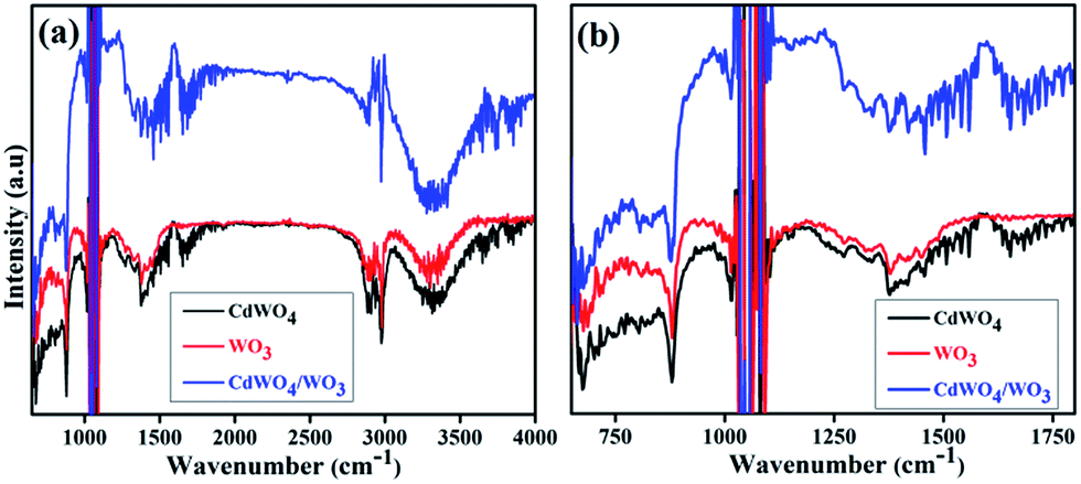
To further confirm the composition information of WO3/CdWO4 composite, Fourier transform infrared (FTIR) spectra of the samples were measured as displayed in Fig. 5. It shows typical FTIR spectra of pure CdWO4, pure WO3 and WO3/CdWO4 Z-scheme photocatalyst respectively. The broad absorption peak around 3428 cm−1 in Fig. 5(a) is associated with H–O vibration for surface hydration layers, and the weak peak around 1633 cm−1 is attributed to H–O–H bonding of the water molecules.22 The two peaks around 1395 and 1568 cm−1 may be assigned to the symmetrical and asymmetrical vibrations of carboxylate groups respectively. The two strong peaks at 1060 cm−1 and 1140 cm−1 are the characteristics of stretching vibrations of C–O of citric species,23 which confirms the presence of CdWO4. A set of peaks below 1000 cm−1 shown in Fig. 5(b) can be ascribed to O–W–O stretching modes of WO3, while the broad bands in the range 3200–3550 cm−1 could be assigned to stretching vibrations of O–H for WO3.24
 |
| | Fig. 5 FTIR spectra of CdWO4, WO3 and WO3/CdWO4 (a) in full range, and (b) in short range. | |
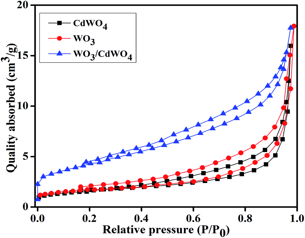
To gain the knowledge about the surface area of the as-prepared photocatalyst, the N2 adsorption–desorption isotherms of all the samples were measured as indicated in Fig. 6. It is well known that high surface area of a photocatalyst is favorable to adsorb organic pollutants from the aqueous solution and increases the contact area between the catalyst and pollutants during the photocatalytic reaction. Therefore, for a material to be a good photocatalyst, its specific surface area is given much importance as it plays significant role during photocatalysis providing more active sites.25 Fig. 6 shows the typical nitrogen adsorption–desorption curves for CdWO4, WO3 and WO3/CdWO4. The BET specific surface area of all the samples was calculated from the data points in the pressure range 0 to 1 by the Brunauer–Emmett–Teller (BET) equation.26 According to these calculations, the BET specific areas of CdWO4, WO3 and WO3/CdWO4 were estimated as 6.844, 7.950 and 15.803 m2 g−1 respectively. In addition, the BET analysis shows that the WO3/CdWO4 photocatalyst has larger specific surface area than both CdWO4 and WO3 that possibly makes it beneficial for the decontamination of organic dyes.
 |
| | Fig. 6 Nitrogen adsorption–desorption curves for CdWO4, WO3 and WO3/CdWO4 respectively. | |
Optical absorption properties
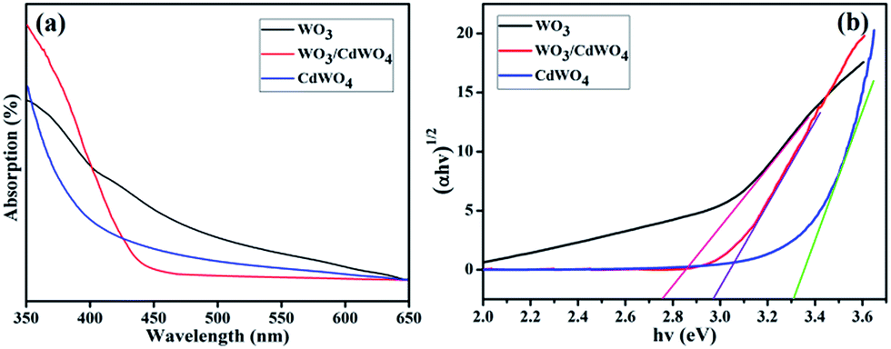
To investigate the optical properties of the fabricated photocatalyst WO3/CdWO4, the UV spectra were measured at room temperature. As indicated in Fig. 7(a), the absorption band edges of CdWO4 and WO3 are around 390 and 420 nm while the absorption band edge of WO3/CdWO4 is located around 460 nm. It can be seen that the absorption edge of WO3/CdWO4 composite sample has shifted significantly towards longer wavelengths as compared to CdWO4 and WO3 which means that the absorption edge of WO3/CdWO4 photocatalyst is shifted to the lower energy region. The optical band gaps, Eg, of all the three samples were calculated by the well-known equation used in ref. 24. The band gaps of CdWO4, WO3 and WO3/CdWO4 photocatalyst were estimated as 3.30, 2.77 and 2.97 eV respectively as can be seen from Fig. 7(b). The band gap of the composite WO3/CdWO4 sample exists between CdWO4 and WO3. This result reveals that the formation of tightly chemically bonded interfaces between CdWO4 and WO3 phases can make WO3/CdWO4 composite photocatalyst shift to the lower energy region.
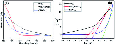 |
| | Fig. 7 (a) UV absorption curves of CdWO4, WO3, and WO3/CdWO4, and (b) band gap of CdWO4, WO3/CdWO4 and WO3. | |
Photocatalytic properties
The photocatalytic activities of the as-synthesized samples Z-scheme WO3/CdWO4 photocatalyst were evaluated under visible light irradiation (λ > 400 nm) by degrading the dyes MO, RhB and MB. The photodegradation curves of MO, RhB and MB in the presence of CdWO4, WO3 and WO3/CdWO4 photocatalysts respectively under visible light can be seen in Fig. S2 (ESI†). It can be seen that the photodegradation of organic dyes takes place as a function of irradiation time in the presence of different sample materials and obeys the first order kinetic reaction. The characteristic absorption curve of each dye decreased with the increase of irradiation time and finally disappeared after a certain time interval. In the absence of any photocatalyst, the self-degradation of organic dyes was almost negligible. Pure CdWO4 and WO3 have some certain photocatalytic efficiency in the photodegradation process and they could degrade about 85% and 90% of the dyes in 150 min and 100 min on the average respectively. It is noted that the photocatalytic performance of CdWO4 was slightly less than that of WO3 but both materials showed the best performance for the degradation of MB than that of MO and RhB as shown in Fig. S2 (ESI†). After combining WO3 with CdWO4, the photocatalytic activity of the heterojunction was significantly increased for the degradation of MO, RhB and MB in comparison to CdWO4 and WO3. It can be noticed from Fig. S2(c, f and i) (ESI†) that WO3/CdWO4 photocatalyst takes 50 min, 40 min and 50 min for the degradation of MO, RhB and MB respectively and efficiently degraded about 95% of the dyes. The best photocatalytic activity of the WO3/CdWO4 photocatalyst was found for the degradation of MB; it degraded 97% of the dye within 50 min as cleared from Fig. S2(i) (ESI†). From an overall view, it can be noticed that all the samples efficiently degraded MB in comparison to MO and RhB respectively.
Kinetics
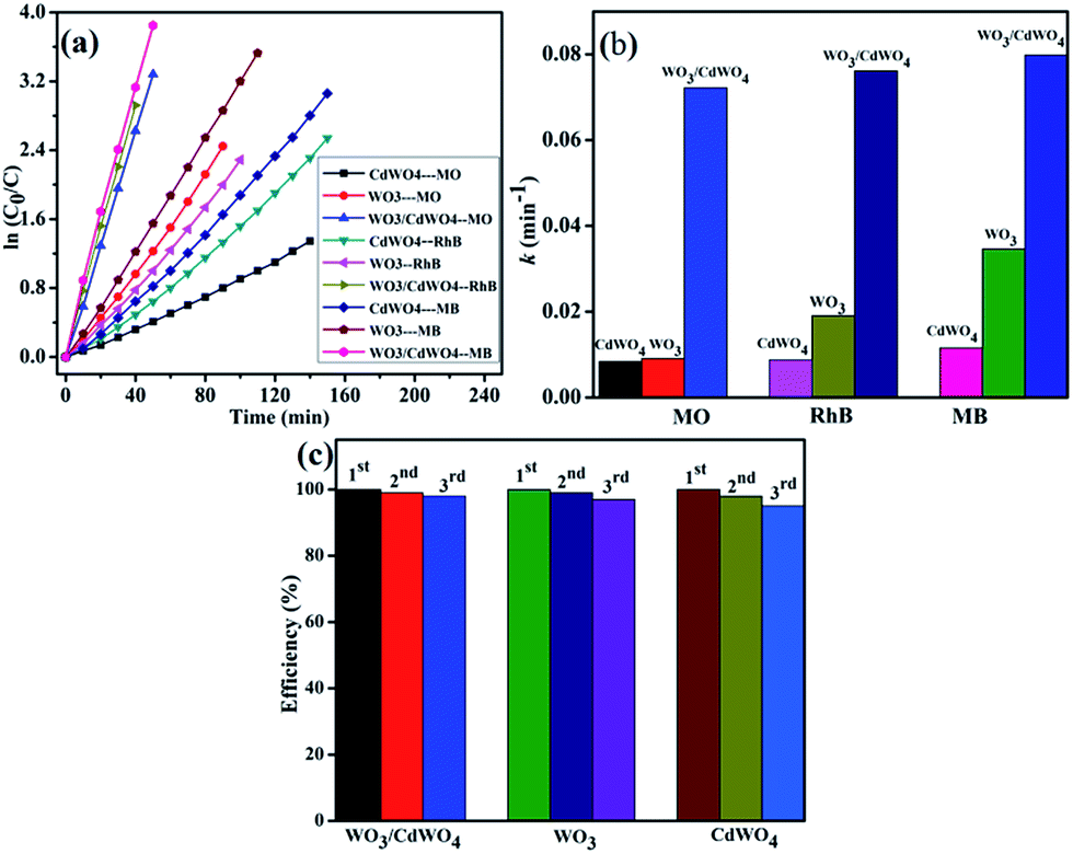
In order to express the reaction kinetics of the organic dyes, we have to deal with the following first order equation:where C0 and C represents the concentrations of dye in the solution at times 0 and t, respectively, and k is the apparent first-order rate constant. The photodegradation kinetics for CdWO4, WO3 and WO3/CdWO4 over the organic pollutants is shown in Fig. 8(a) by plotting a graph between ln(C0/C) and irradiation time t that are almost straight lines indicating that the photodegradation reaction obeys the first-order kinetics. From Fig. 8(b), the pseudo-first-order rate constants (k) for the degradation of MO, RhB and MB with WO3/CdWO4 under visible light irradiation were calculated as 0.07221 m−1, 0.07614 m−1 and 0.07982 m−1 respectively. It can be seen that WO3/CdWO4 photocatalyst showed the enhanced photocatalytic activity for the degradation of pollutants compared to pure CdWO4 and pure WO3. In the WO3/CdWO4 system, the photocatalyst exhibited the photocatalytic performance about 7 times greater than the bare CdWO4 (0.01155 m−1) and about 2.3 times greater than bare WO3 (0.03459 m−1) for the case of MB degradation. The enhancement could be ascribed to the introduction of WO3 into the composite sample, which can induce higher adsorption activity for organic dyes and higher migration efficiency of photo-generated charge carriers. Fig. 8(c) shows the stability WO3/CdWO4, WO3 and CdWO4 for the case of MB degradation. For the recycling process, the catalyst samples were centrifuged, dried at 80 °C for 12 hours and then reused for degradation of the same concentration of the dye. The samples were recycled for 3 times and the results showed excellent stability and recycling capability (Fig. 8(c)). The materials took almost same time for degradation without any significant loss of efficiency even after 3rd cycle. The stability of the samples for the degradation of RhB and MO are given in Fig. S3 (ESI†). The apparent rate constants of all the samples and relative coefficients are summarized in Table 1. The photocatalytic performance of the as-synthesized photocatalyst in comparison to CdWO4 and WO3 for the degradation of MO and RhB can also be studied from this table.
 |
| | Fig. 8 (a) First order kinetic fit for the degradation MO, RhB and MB with CdWO4, WO3 and WO3/CdWO4 respectively, (b) apparent first order rate constants for all samples, and (c) the stability test of WO3/CdWO4,WO3 and CdWO4 for the case of MB degradation. | |
Table 1 The values of rate constants CdWO4, WO3, and WO3/CdWO4 for the degradation of MB, RhB and MO respectively
| Dye |
k for CdWO4 |
k for WO3 |
k for WO3/CdWO4 |
| MB |
0.0115 min−1 |
0.03459 min−1 |
0.07982 min−1 |
| RhB |
0.00875 min−1 |
0.01907 min−1 |
0.07614 min−1 |
| MO |
0.00837 min−1 |
0.00907 min−1 |
0.07221 min−1 |
Possible mechanism for enhanced photocatalytic activity of Z-scheme WO3/CdWO4 photocatalyst
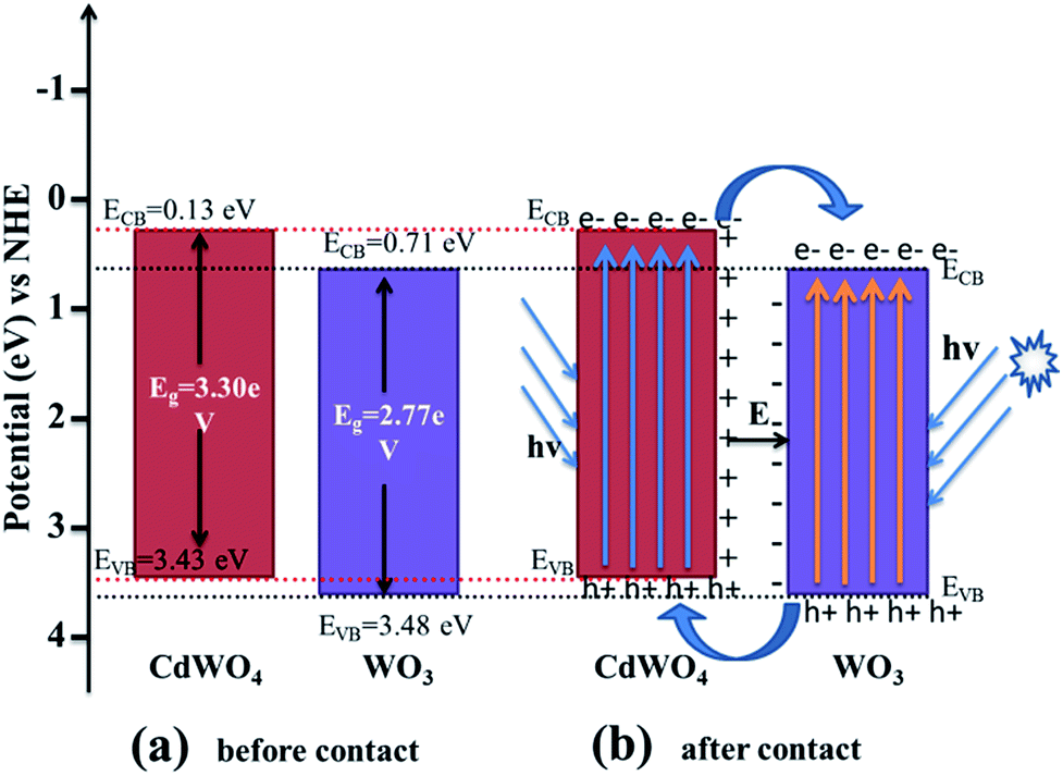
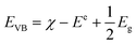
It is well known that there are some crucial factors like adsorption ability, optical absorption, phase structure and separation efficiency of photo-generated charge carriers that influence the photocatalytic activity.27 However, to fully understand the photocatalytic reaction mechanism occurring during the photodegradation of as-prepared WO3/CdWO4 photocatalyst, the band edge positions of the valence band (VB) and conduction band (CB) of both CdWO4 and WO3 are necessary to be determined because they have strong relation with the photocatalytic oxidation process of organic compounds. The valence band potentials of CdWO4 and WO3 were calculated according to the following empirical equations:28| |
 | (2) |
where EVB and ECB are the valence band and conduction band edge potentials respectively, χ is the electronegativity of the semiconductor, which is the geometric mean of the electronegativity of the constituent atoms. The values of χ for CdWO4 and WO3 have been calculated as 6.28 eV and 6.59 eV according to literature.29 Ee is the energy of free electrons on the hydrogen scale (about 4.5 eV) and Eg is the band gap energy of the semiconductor. On the basis of band gap positions, the band edge potentials of VB and CB for WO3 (ref. 30) are 3.48 eV and 0.71 eV while for CdWO4 are 3.43 eV and 0.13 eV respectively. The schematic illustration of energy band structure of WO3 and CdWO4 is presented in Fig. 9.
 |
| | Fig. 9 Schematic diagram of (a) band energy of CdWO4 and WO3 before contact and (b) formation of a p–n junction and the proposed charge separation process of WO3/CdWO4 heterostructures under visible-light irradiation. | |
After bringing the two materials CdWO4 and WO3 in contact, the electrons from the CB of CdWO4 started to diffuse into the CB of WO3 as the CB potential of CdWO4 is at lower potential than that of WO3. As a result, negative charges will accumulate in WO3 near the interface. Simultaneously, the holes from VB of WO3 move into the VB of CdWO4 because the VB of WO3 is at higher potential than that of CdWO4. This movement of the holes gives rise to a layer of positive charges in CdWO4 near the interface between two semiconductors. So an electric field is established between the interfaces as shown in Fig. 9. The equilibrium between CdWO4 and WO3 is established when the Fermi levels are reached and the further diffusion of electrons from CdWO4 to WO3 is stopped. In the presence of visible light irradiation, both CdWO4 and WO3 absorb photons of energy equal to or greater than the corresponding band gap energy, that cause to excite the electrons in the VB to the CB and leave holes in the VB of both materials. The excited electrons present in the CB of CdWO4 are then transferred to the CB of WO3, and the holes are left in the VB of CdWO4. The inner established electric field (E) at the heterojunction interfaces promotes this transfer of photo-induced charge carriers. The photo-induced electron–hole pairs are thus effectively separated because of a junction formed between CdWO4 and WO3 interface, resulting in the slow-down recombination photo-generated electron–hole pairs. As a result, the photocatalytic activity of the Z-scheme photocatalyst WO3/CdWO4 was improved. This conclusion can be verified by the PL spectra of all the three samples.
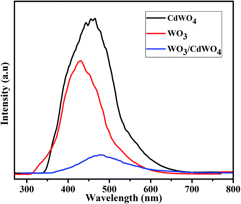
In order to investigate the fact of photo-generated electron–hole pairs in the product and to understand the possible mechanism, the photoluminescence emission spectra were measured, since the PL emission spectra originate from the recombination of free charge carriers in a semiconducting material and there is a strong link between PL intensity and the photocatalytic efficiency. Generally, a higher PL intensity shows a higher recombination rate of photo-generated charge carriers which leads to a lower photocatalytic performance. On the other hand, a lower PL intensity shows a lower recombination rate of photo-generated electron–hole pairs, indicating that more photo-generated electrons and holes can participate in the oxidation and reduction reactions and as a result the photocatalytic performance is improve.31 Fig. 10 shows the PL spectra of rods-like CdWO4 microstructures, WO3 microsheets and WO3/CdWO4 composite at room temperature in the wavelength range of 270–800 nm with an excitation wavelength of 235 nm. The PL emission peak for pure CdWO4 centred at 463 nm whereas for pure WO3 at 427 nm. It has been noticed that the coupling of WO3 microsheets with rods-like CdWO4 had significant effect on the PL intensity of the obtained composite WO3/CdWO4. It can be that the PL intensity of composite dramatically decreased by the introduction of WO3. The intensity peak for WO3/CdWO4 appeared at 476 nm which may be ascribed to the band gap recombination of electron–hole pairs. It can be noted that the addition of WO3 to CdWO4 not only alters the spectral position of the peak but also decreased the relative PL intensity of the as-prepared composite sample. These findings reveal that the heterojunction/synergistic effect between WO3 and CdWO4 plays an important role in the effective electron–hole separation that might be a reason for the superior photocatalytic activity of Z-scheme WO3/CdWO4 photocatalyst under visible light irradiation environment. The efficient separation of photo-generated electron–hole pairs in WO3/CdWO4 photocatalyst was confirmed by the PL emission spectra as it is strongly correlated with the transfer behaviour of photo-generated electron–hole pairs in semiconductors.32 On the addition of WO3 to CdWO4, the surface recombination of electrons and holes was inhibited, therefore the PL intensity of the final product is decreased which shows that the recombination rate of photo-generated charge carriers in the composite sample has slowed down and as a result higher photocatalytic activity is achieved. The decreased PL intensity of WO3/CdWO4 photocatalyst is thus an obvious evident of high quantum efficiency and high photocatalytic activity. Finally, the increased surface area (15.803 m2 g−1) of the composite WO3/CdWO4 as compared to CdWO4 and WO3 played an important role in the enhancement of its catalytic activity. The larger surface area of the catalyst provides more active sites for photocatalytic reaction, resulting in higher catalytic activity.
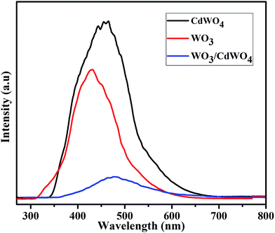 |
| | Fig. 10 Photoluminescence (PL) spectra of CdWO4, WO3 and WO3/CdWO4 at room temperature. | |
Conclusion
A novel Z-scheme WO3/CdWO4 photocatalyst has been synthesized by a simple mixing and heating method. The as-prepared WO3/CdWO4 photocatalyst exhibited high photocatalytic efficiency for the degradation of different organic pollutants under visible light irradiation. It was noticed that the photocatalytic performance of the composite WO3/CdWO4 was much higher than that of either WO3 or CdWO4 for the degradation of each organic dye. The highest activity of the composite was recorded for the degradation of MB which was about 7 times greater than pure CdWO4 and 2.3 times than that of pure WO3. The enhanced photocatalytic performance of the composite/photocatalyst was mainly ascribed to the increased surface area and introduction of WO3 into the composite sample, which can induce higher adsorption activity for organic dyes and the increased electron–hole separation at the interface of two semiconductors by establishing an inner electric field.
Acknowledgements
This work was supported by National Natural Science Foundation of China (23171023, 50972017) and the Research Fund for the Doctoral Program of Higher Education of China (20101101110026).
Notes and references
- A. Fujishima and K. Honda, Nature, 1972, 238, 37 CrossRef CAS.
-
(a) M. A. Shannon, P. W. Bohn, M. Elimelech, J. G. Georgiadis, B. J. Mariñas and A. M. Mayes, Nature, 2008, 452, 301 CrossRef CAS PubMed;
(b) T. Ochiai, H. Nanba, T. Nakagawa, K. Masuko, K. Nakata, T. Murakami, R. Nakano, M. Hara, Y. Koide, T. Suzuki, M. Ikekita, Y. Morito and A. Fujishima, Catal. Sci. Technol., 2012, 2, 76 RSC;
(c) N. Serpone and A. V. Emeline, J. Phys. Chem. Lett., 2012, 3, 673 CrossRef CAS.
- R. Abe, T. Takata, H. Sugihara and K. Domen, Chem. Commun., 2005, 3829 RSC.
-
(a) J. W. Tang, Z. G. Zou and J. H. Ye, Chem. Mater., 2004, 16, 1644 CrossRef CAS;
(b) Y. Wang and G. Z. Cao, J. Mater. Chem., 2007, 17, 894 RSC;
(c) U. M. García Pérez, S. Sepúlveda-Guzmán, A. Martínez-de la Cruz and U. Ortiz Méndez, J. Mol. Catal. A: Chem., 2011, 335, 169 CrossRef PubMed;
(d) W. M. Tong, L. P. Li, W. B. Hu, T. J. Yan and G. S. Li, J. Phys. Chem. C, 2010, 114, 1512 CrossRef CAS;
(e) S. J. Liang, X. W. Wang, Y. Chen, J. Zhu, Y. F. Zhang, X. X. Wang, Z. H. Li and L. Wu, Nanoscale, 2010, 2, 2262 RSC;
(f) C. B. Park, S. H. Lee, E. Subramanian and B. B. Kale, Chem. Commun., 2008, 5423 RSC.
-
(a) R. Asahi, T. Morikawa, T. Ohwaki, K. Aoki and Y. Taga, Science, 2001, 293, 269 CrossRef CAS PubMed;
(b) M. Hassan Farooq, R. Hussain, L. Zhang, I. Aslam, M. Tanveer, M. W. Shah and M. Zubair Iqbal, Mater. Lett., 2014, 131, 350 CrossRef PubMed.
- S. Linic, P. Christopher and D. B. Ingram, Nat. Mater., 2011, 10, 911 CrossRef CAS PubMed.
-
(a) A. Kubacka, M. Fernández-García and G. Colón, Chem. Rev., 2012, 112, 1555 CrossRef CAS PubMed;
(b) F. Idrees, C. Cao, F. K. Butt, M. Tahir, M. Tanveer, I. Aslam, Z. Ali, T. Mahmood and J. Hou, CrystEngComm, 2013, 15, 8146 RSC;
(c) M. Tanveer, C. Cao, W. S. Khan, Z. Ali, I. Aslam, F. K. Butt, F. Idrees, M. Tahir and N. Mahmood, CrystEngComm, 2014, 16, 5290 RSC.
-
(a) H. G. Yang, C. H. Sun, S. Z. Qiao, J. Zou, G. Liu, S. C. Smith, H. M. Cheng and G. Q. Lu, Nature, 2008, 453, 638 CrossRef CAS PubMed;
(b) M. Tahir, C. Cao, F. K. Butt, S. Butt, F. Idrees, Z. Ali, I. Aslam, M. Tanveer, A. Mahmood and N. Mahmood, CrystEngComm, 2014, 16, 1825 RSC;
(c) M. Tahir, C. Cao, F. K. Butt, F. Idrees, N. Mahmood, Z. Ali, I. Aslam, M. Tanveer, M. Rizwan and T. Mahmood, J. Mater. Chem. A, 2013, 1, 13949 RSC.
-
(a) A. Tanaka, K. Hashimoto and H. Kominami, J. Am. Chem. Soc., 2014, 136, 586 CrossRef CAS PubMed;
(b) I. Aslam, C. Cao, W. S. Khan, M. Tanveer, M. Tahir, M. Abid, F. Idrees, F. K. Butt, Z. Ali and N. Mahmood, New J. Chem., 2014, 38, 5462 RSC.
-
(a) K. Sayama, K. Mukasa, R. Abe, Y. Abe and H. Arakawa, Chem. Commun., 2001, 2416 RSC;
(b) R. Abe, K. Sayama and H. Sugihara, J. Phys. Chem. B, 2005, 109, 16052 CrossRef CAS PubMed;
(c) K. Maeda, M. Higashi, D. Lu, R. Abe and K. Domen, J. Am. Chem. Soc., 2010, 132, 5858 CrossRef CAS PubMed;
(d) Y. Sasaki, H. Kato and A. Kudo, J. Am. Chem. Soc., 2013, 135, 5441 CrossRef CAS PubMed;
(e) K. Maeda, ACS Catal., 2013, 3, 1486 CrossRef CAS.
-
(a) T. B. Li, G. Chen, C. Zhou, Z. Y. Shen, R. C. Jin and J. X. Sun, Dalton Trans., 2011, 6751 RSC;
(b) J. Jiang, X. Zhang, P. B. Sun and L. Z. Zhang, J. Phys. Chem. C, 2011, 115, 20555 CrossRef CAS;
(c) Y. Y. Wen, H. M. Ding and Y. K. Shan, Nanoscale, 2011, 3, 4411 RSC;
(d) X. Q. An, J. C. Yu, Y. Wang, Y. M. Hu, X. L. Yu and G. J. Zhang, J. Mater. Chem., 2012, 22, 8525 RSC;
(e) K. H. Reddy, S. Martha and K. M. Parida, Inorg. Chem., 2013, 52, 6390 CrossRef CAS PubMed;
(f) J. X. Wang, P. X. Wang, Y. T. Cao, J. Chen, W. J. Li, Y. Shao, Y. Zheng and D. Z. Li, Appl. Catal., B, 2013, 136, 94 CrossRef PubMed;
(g) J. J. Guo, S. X. Ouyang, P. Li, Y. J. Zhang, T. Kako and J. H. Ye, Appl. Catal., B, 2013, 134, 286 CrossRef PubMed.
-
(a) C. Yu, G. Li, S. Kumar, K. Yang and R. Jin, Adv. Mater., 2014, 26, 892 CrossRef CAS PubMed;
(b) C. Yu, L. Wei, J. Chen, Y. Xie, W. Zhou and Q. Fan, Ind. Eng. Chem. Res., 2014, 53, 5759 CrossRef CAS;
(c) X. Zong, H. Yan, G. Wu, G. Ma, F. Wen, L. Wang and C. Li, J. Am. Chem. Soc., 2008, 130, 7176 CrossRef CAS PubMed;
(d) J. Zhang, Q. Xu, Z. Feng, M. Li and C. Li, Angew. Chem., Int. Ed., 2008, 47, 1766 CrossRef CAS PubMed.
- F. Masami, I. Minoru, K. Tsuoshi, I. Daisuke, K. Mamoru and B. M. Vitalii, Phys. Rev. B: Condens. Matter Mater. Phys., 2008, 77, 155118 CrossRef.
-
(a) X. Zhao and Y. Zhu, Environ. Sci. Technol., 2006, 40, 3367 CrossRef CAS;
(b) J. Lin, J. Lin and Y. Zhu, Inorg.
Chem., 2007, 46, 8372 CAS;
(c) H. Fu, C. Pan, W. Yao and Y. Zhu, J. Phys. Chem. B, 2005, 109, 22432 CrossRef CAS PubMed;
(d) D. Ye, D. Li, W. Zhang, M. Sun, Y. Hu, Y. Zhang and X. Fu, J. Phys. Chem. C, 2008, 112, 17351 CrossRef CAS;
(e) W. Tong, L. Li, W. Hu, T. Yan and G. Li, J. Phys. Chem. C, 2010, 114, 1512 CrossRef CAS;
(f) Y. Wang, X. Guan, L. Li, H. Lin, X. Wang and G. Li, New J. Chem., 2012, 36, 1852 RSC;
(g) D. Li, X. Bai, J. Xu, X. Mac and Y. Zhu, Phys. Chem. Chem. Phys., 2014, 16, 212 RSC.
- Y. Abraham, N. A. W. Holzwarth and R. T. Williams, Phys. Rev. B: Condens. Matter, 2000, 62, 1733 CrossRef CAS.
- T. J. Yan, L. P. Li, W. M. Tong, J. Zheng, Y. J. Wang and G. S. Li, J. Solid State Chem., 2011, 184, 357 CrossRef CAS PubMed.
- X. C. Zhang, X. X. Liu, C. M. Fan, Y. W. Wang, Y. F. Wang and Z. H. Liang, Appl. Catal., B, 2013, 132, 332 CrossRef PubMed.
- D. Ye, D. Z. Li, W. Chen, Y. Shao, G. C. Xiao and M. Sun, Res. Chem. Intermed., 2009, 35, 675 CrossRef CAS.
- L. Wang and W. Z. Wang, CrystEngComm, 2012, 14, 3315 RSC.
- J. Xu, M. Chen and Z. Wang, Dalton Trans., 2014, 3537 RSC.
-
(a) S. Anandan and M. Miyauchi, Chem. Commun., 2012, 48, 4323 RSC;
(b) W. Morales, M. Cason, O. Aina, N. R. de Tacconi and K. Rajeshwar, J. Am. Chem. Soc., 2008, 130, 6318 CrossRef CAS PubMed;
(c) B. Zhang, C. Cao, H. Qiu, Y. Xu, Y. Wang and H. Zhu, Chem. Lett., 2005, 34, 154 CrossRef CAS;
(d) K. Mingyang, C. Chuanbao, X. Xingyan and L. Bo, Chin. Sci. Bull., 2008, 53, 335 CrossRef.
-
(a) W. B. Hu, L. P. Li, G. S. Li, J. Meng and W. M. Tong, J. Phys. Chem. C, 2009, 113, 16996 CrossRef CAS;
(b) G. S. Li, L. P. Li, J. Boerio-Goates and B. F. Woodfield, J. Am. Chem. Soc., 2005, 127, 8659 CrossRef CAS PubMed.
- Y. G. Su, G. S. Li, Y. F. Xue and L. P. Li, J. Phys. Chem. C, 2007, 111, 6684 CAS.
- I. Aslam, C. Cao, W. S. Khan, M. Tanveer, M. Abid, F. Idrees, R. Riasat, M. Tahir, F. K. Butt and Z. Ali, RSC Adv., 2014, 4, 37914 RSC.
-
(a) R. Narayanan and M. A. El-Sayed, Nano Lett., 2004, 4, 1343 CrossRef CAS;
(b) C. Ye, Y. Bando, G. Shen and D. Golberg, J. Phys. Chem. B, 2006, 110, 15146 CrossRef CAS PubMed;
(c) L. Zhang, H. Yang, J. Yu, F. Shao, L. Li, F. Zhang and H. Zhao, J. Phys. Chem. C, 2009, 113, 5434 CrossRef CAS.
- S. Brunauer, P. H. Emmett and E. Teller, J. Am. Chem. Soc., 1938, 60, 309 CrossRef CAS.
- J. Xu, M. Chen and Z. Wang, Dalton Trans., 2014, 3537 RSC.
-
(a) M. Sadakane, K. Sasaki, H. Kunioku, B. Ohtani, R. Abe and W. Ueda, J. Mater. Chem., 2010, 20, 1811 RSC;
(b) C. Feng, S. Wang and B. Geng, Nanoscale, 2011, 3, 3695 RSC.
- R. G. Pearson, Inorg. Chem., 1988, 27, 734 CrossRef CAS.
- X. Luo, F. Liu, X. Li, H. Gao and G. Liu, Mater. Sci. Semicond. Process., 2013, 16, 1613 CrossRef CAS PubMed.
-
(a) Q. Xiao, Z. Si, J. Zhang, C. Xiao and X. Tan, J. Hazard. Mater., 2008, 150, 62 CrossRef CAS PubMed;
(b) Y. Yang, G. Zhang, S. Yu and X. Shen, Chem. Eng. J., 2010, 162, 171 CrossRef CAS PubMed;
(c) H. Huang, D. Li, Q. Lin, W. Zhang, Y. Shao, Y. Chen, M. Sun and X. Fu, Environ. Sci. Technol., 2009, 43, 4164 CrossRef CAS.
- L. Jing, H. Fu, B. Wang, D. Wang, B. Xin, S. Li and J. Sun, Appl. Catal., B, 2006, 62, 282 CrossRef CAS PubMed.
Footnote |
| † Electronic supplementary information (ESI) available. See DOI: 10.1039/c4ra15847d |
|
| This journal is © The Royal Society of Chemistry 2015 |
Click here to see how this site uses Cookies. View our privacy policy here.