Effective denitrification process by a low voltage in a multi-cathode bio-electrode film reactor

Ruqiong Caoa, Diwen Yingb, Chenjun Lia, Yalin Wanga and Jinping Jia*a
aSchool of Environmental Science and Engineering, Shanghai Jiao Tong University, 800 Dongchuan Road, Shanghai, 200240, P. R. China. E-mail: jpjia@sjtu.edu.cn; Fax: +86 021 5474 2817; Tel: +86 021 5474 2817
bSchool of Material Science and Engineering, Shanghai Jiao Tong University, 800 Dongchuan Road, Shanghai, 200240, P. R. China

Received 4th December 2014 , Accepted 13th January 2015

First published on 13th January 2015


Abstract

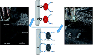
A multi-cathode bio-electrode film reactor driven by a low voltage was applied for the denitrification process. The reactor was evaluated with simulated wastewater (120 NO3–N mg L−1) under a series of applied voltages (less than 0.5 V), and the applied voltage of 0.25 V was identified as the optimum for the best nitrate removal rate of 16.8 NO3–N mg L−1 h−1 in 6 h. The analysis of the nitrogen balance showed that nitrite accumulation occurred a little, while there was an absence of ammonia during the denitrification process. The investigation of the denitrification mechanism showed the presence of some bacterial species on the cathode biofilm, which accounted for the direct electron transport pathway. The main experimental conditions of pH and temperature were optimized under 0.25 V with an optimum pH range of 7.0–8.0 and comfortable temperature of 30 °C. It seemed to be an effective approach for the denitrification with a low energy input.


1 Introduction

Nitrate pollution in groundwater is widespread, due to excessive use of fertilizers and industrial materials,1 and has resulted in severe impacts on human health.2 Due to the lack of suitable electron donors and nitrate's mobility in groundwater, the removal of nitrate from groundwater in an effective and efficient way is a great challenge. The chemical nitrate removal method requires the addition of chemical compounds that may cause secondary pollution,3 while physical methods, such as reverse osmosis (RO), ion exchange (IEX), and electro dialysis (ED),4 have a high cost. Thus, the bio-electrode reactor (BER) method has been studied a lot for its in situ electron donor and bio-electrochemical process.5

BER was proposed by Sakakibara in 1993,6 but the improvement on BER reactor and the study on the mechanism had never stopped. Several BER reactors were developed for nitrate removal through bio-electrochemical process,7–9 aiming to reduce energy consumption and enhance nitrate removal efficiency. The traditional understanding on BER mechanism was that hydrogen produced on cathodes acted as the electron donor.10 Based on this mechanism, a potential concern of using BER for nitrate remediation was the low efficiency of electrical energy, for the high resistance existing in the reactor and the low solubility of hydrogen in water. Zhao et al. reported that the optimum voltage ranged from 0.5 V to 30 V, due to the different design of reactors, application of cathode materials, acclimatization of bacteria and others.11 Also, Clauwaert and Virdis et al. have widely studied on the operational parameters for BER including the C/N ratio, the dissolved oxygen level and the loading rate.12,13 Moreover, it was demonstrated that in microbial fuel cells (MFC), there might be Geobacter species on the anodes, which could transport electrons directly from microorganism to the anodes.14,15 Bond et al. used electrochemical method to confirm the feasibility of direct electron transport process by Geobacter in nitrate removal.16 It also mentioned that it's feasible for Geobacter to exist in BER but harder than in MFC.15 But till now, there is no systematic study to show what is the denitrification performance of BER driven by Geobacter and what is the optimized voltage, pH and temperature for Geobacter to exist on cathode acting as the sole electron donor in the denitrification process. Furthermore, the morphology characteristics of Geobacter coupled with biological analysis were just budding.

In this study, a traditional multi-cathode bio-electrode film reactor was applied to investigate the denitrification performance under a series of low applied voltage (less than 0.5 V), aiming to fix the optimized voltage for denitrification driven by direct electron transport process. The denitrifying bacteria were acclimated by a potentiostat-poised graphite ACF electrode in the solution with a high C/N ratio, all of which would benefit Geobacter's survival. Current-denitrification efficiency was calculated based on the nitrate removal, and nitrite and ammonia accumulation were tested for the nitrogen balance analysis. Furthermore, the optimized conditions of pH and temperature for Geobacter, in terms of nitrate removal under an applied voltage of 0.25 V were identified.

2 Material and methods

2.1 Bio-electrode film reactor set-up

Schematic setup of a multi-cathode bio-electrode film reactor in this study was shown in Fig. 1. This reactor was consisted of two large cathodes (7 cm × 10 cm) and three small anodes (3.5 cm × 5 cm), in parallel in a sealed grass beaker. The gap between the cathodes and anodes was 1 cm. All electrodes were made of graphitized ACF, which had excellent biocompatibility and good conductivity.17 ACF electrodes ware fixed by acrylonitrile butadiene styrene copolymers (ABS) plastic frame (2 mm thick, Jinlaida Co. Ltd., China). The working volume of BER was 1.0 L, with the working surface area of 140 cm2 per piece (the cathode) and 35 cm2 per piece (the anode). The anodes were separated from the denitrifying bacteria with gauze to avoid negative influence of anodes on denitrifying bacteria. The fixed voltages were supplied by a DC power supply (JS1003D, ANS Co. Ltd., China) and temperature of the whole grass beaker was kept by a water bath (220V/300W, EHEIM Co. Ltd., China). A magnetic stirrer (B11-1, Shanghai Sile Co. Ltd., China) was installed right beneath the water bath with a speed of 80 rpm, and the frequency was 5 min in one cycle controlled by a timer.
image file: c4ra15792c-f1.tif
Fig. 1 Schematic setup of bio-electrode denitrification reactor carried out with biofilm on large active carbon fiber cathodes and small sealed small carbon counter anodes. 1-glass container, 2-sealed cap, 3-small active carbon anode with gauze covering around all the surface, 4-large active carbon cathode with naked hydrophilic surface, 5-pH meter, 6-direct current (DC) power supply, 7-water bath with constant temperature controller, 8-magnetic stirrer.

2.2 Bacteria inoculation and biofilm acclimatization

The sludge used as inoculum was obtained from the secondary sedimentation tank of a municipal wastewater treatment plant in Shanghai, China, which had a capacity of 50[thin space (1/6-em)]000 m3 per day with the anaerobic–anoxic–aerobic process. 20 mL sludge was put into each reactor with a total solid of 39.7 ± 0.2 g L−1. The biofilm was initially formed and acclimated under a culture solution containing sodium nitrate 0.8 g L−1, methanol 3.5 mL L−1, monopotassium phosphate 0.175 g L−1 and dipotassium hydrogen phosphate 0.175 g L−1 at the temperature of 30 °C. The initial concentration of nitrate was 120 NO3–N mg L−1, with a C/N ratio of 5 and pH 7.2 ± 0.2. Concentrated culture solution was added every 24 hours and the hydraulic detention time (HRT) was 7 days. The intermittent agitation was conducted to avoid the introduction of air and created an anoxic environment. During the initial acclimation stage without external voltage (referred to as Stage 1), the concentration of nitrate was tested and the acclimatization process continued till the denitrification rate was stable. Then the following stages were conducted with an increasing voltage of 0.125 V, 0.25 V, 0.375 V and 0.50 V (Stage 2, Stage 3, Stage 4 and Stage 5). In these stages, the concentrations of nitrite and ammonia were also investigated. All experiments were repeated three times to obtain average values with an accuracy of ±5%.

2.3 Experimental optimization of biofilm electrode reactor

The main experimental conditions, such as pH and temperature, were further optimized under the optimal voltage, and methanol, monopotassium phosphate and dipotassium hydrogen phosphate were added into the culture according to comfortable C/N/P (5[thin space (1/6-em)]:[thin space (1/6-em)]1[thin space (1/6-em)]:[thin space (1/6-em)]0.125) for denitrification process. A range of 6.0, 7.0, 8.0 and 9.0 was set under the temperature of 30 °C, which was a suitable temperature for denitrifying bacteria of Geobacter,18 and then the temperature gradient of 20 °C, 25 °C, 30 °C and 35 °C was set at the optimal pH. Operational conditions (temperature and pH) for each run were maintained until a stable denitrification performance was achieved. The solution was sampled each hour and the concentration of nitrate, nitrite and ammonia were all measured.

2.4 Analytical methods

The concentration of nitrate was measured by a UV-vis spectrophotometer (UV-2102PCS, UNICO, Shanghai) at the absorbance wavelength of 220 nm and 275 nm as described by Luo et al.19 The concentration of nitrite and ammonia were detected according to APHA.20 And the nitrate removal rate (NRR) and nitrate removal efficiency (NRE) were calculated as the denitrification performance of the system:
 
image file: c4ra15792c-t1.tif(1)
 
image file: c4ra15792c-t2.tif(2)
Where C0 and Ct (mg L−1) are the initial and finial concentration of NO3–N, respectively; HRT (h) is the operating time.

The current denitrification efficiency (η) defined by

 
image file: c4ra15792c-t3.tif(3)
where V is the volume of reactor (L), CNO3−end and CNO3 are eventual and initial concentrations of nitrate (g L−1), M is nitrate's molar mass (62 g mol−1), n is stoichiometric coefficient (n = 5) and F is Faraday's constant (C mol−1).

ORP was measured by an ORP meter (ORP-502, Ruosull Technology Co. Ltd., Shanghai), and pH by a pH meter (pHs-3C, Leici Co. Ltd., Shanghai), respectively. The current and voltage were detected by an on-line amperemeter (CHI832C, Shanghai Chenhua Co. Ltd., China) and voltmeter (CHI600C, Shanghai Chenhua Co. China). The real-time temperature of solution inside the reactor is detected by a thermo-sensor during the experiments. The SEM of the biofilm was performed by Sirion 200 field emission scanning electron microscope (FESEM). Two universal primers for bacteria, 27F (5′-AGAGTTTGATCCTGGCTCAG-3′) and 533R (5′-TTACCGCGGCTGCTGGCAC-3′) were used to amplify bacteria 16S rDNA gene. PCR products of 16S rDNA gene were determined by pyrosequencing using the Roche 454 FLX Titanium sequencer (Roche 454 Life Sciences, Branford, CT, USA) according to the methodology described by Zhang et al.21

3 Results and discussion

3.1 Effect of applied voltage on nitrate removal

The degradation of nitrate in the BER under different applied voltages was shown in Fig. 2a. The concentration of nitrate decreased in 6 h without external voltage (Stage 1) at a rate of 8.50 NO3–N mg L−1 h−1. Generally, different degrees of NRR were observed in the stages of 2, 3, 4 and 5 with the applied voltage of 0.125 V, 0.25 V, 0.375 V and 0.50 V. In Stage 2–5, the denitrification rates increased compared to the Stage 1 without applied voltage, and the best denitrification performance was obtained in Stage 3 with a significant increase of NRR of 16.58 NO3–N mg L−1 h−1. As shown in Fig. 2b, the decrease in Nitrate–N followed first-order kinetic rate in all stages with R2 of 0.9850, 0.9511, 0.9861, 0.9850 and 0.9724, respectively. The k in the equations, indicating the corresponding NRR, was calculated and the highest value of 0.0040 was also achieved in Stage 3, which was in accordance with the outstanding denitrification performance.
image file: c4ra15792c-f2.tif
Fig. 2 (a) The change of nitrate concentration with time at different applied voltages. Stage 1: applied voltage of 0 V; Stage 2: applied voltage of 0.125 V; Stage 3: applied voltage of 0.25 V; Stage 4: applied voltage of 0.375 V; Stage 5: applied voltage of 0.50 V. Operational conditions: 120 NO3–N mg L−1, original pH 7.2 ± 0.2, C/N ratio 5[thin space (1/6-em)]:[thin space (1/6-em)]1, temperature 30 ± 1 °C. (b) Nitrate degradation rate at different applied voltages.

Driven by direct electron transport process, the applied voltage could enhance the denitrification rate with increasing applied voltage due to the supply of electron for the denitrification process at the cathodes. However, the effects of voltage became gradually insignificant and a declined denitrification performance was obtained with the increase of applied voltage above 0.25 V. The non-existent synergistic effect of multi-pathway denitrification could be explained by the ionic constituent of NO3 which resulted in part of NO3 migrated towards anode without sufficient treatment.22

3.2 Fate of nitrate nitrogen and current-denitrification efficiency

During the denitrification process, the accumulation of main intermediate products had a significant effect on the nitrogen balance.23 Gregory also pointed out that nitrite would accumulate in this process.24 To investigate the fate of nitrate in the optimal voltage of 0.25 V during the degradation of nitrate in Stage 1 and 3 (Fig. 3a), the concentrations of nitrite and ammonia were tested and shown in Fig. 3b and c. In the initial stage, the accumulation of nitrite was observed under applied voltage of 0 V (Stage 1) and 0.25 V (Stage 3) with an accumulation rate of 0.59 NO2–N mg L−1 h−1 and 1.43 NO2–N mg L−1 h−1, respectively (Fig. 3b). Meanwhile, a similar trend of nitrite accumulation in Stage 3 was observed, compared with the traditional denitrification process as reported,25 namely, the accumulation of nitrite tended to peak initially, followed by a decrease. In this experiment, the peak reached at the 4th hour under the applied voltage of 0.25 V in Stage 3, while nitrite accumulation continued to the end of the experiment in Stage 1 without applied voltage. The nitrite accumulation with a faster rate and earlier peak appearing in Stage 3 revealed that, not only the reaction rate from nitrate to nitrite, but also nitrite to nitrous oxide and nitrogen gas was accelerated owing to the applied voltage of 0.25 V.
 
NO3 + H2O + 2e → NO2 + 2OH (4)
 
2NO2 + 3H2O + 4e → N2O + 6OH (5)
 
2NO2 + 4H2O + 6e → N2 + 8OH (6)

image file: c4ra15792c-f3.tif
Fig. 3 The accumulation of nitrite (b) and ammonia (c) during the degradation of nitrate (a) in a BER with applied voltage of 0 V, 0.25 V and in a multi-electrode reactor applied with 0.25 V without bio-film, (d) the composition of nitrogen element in the denitrification process in 5 h.

The low concentration of ammonia and no accumulation were observed in both Stage 1 and Stage 3 (Fig. 3c), which were less than 1% in total nitrogen (TN). The nitrogen balance analysis in Stage 1 and Stage 3 showed that, 46 mg L−1 and 80 mg L−1 nitrate was reduced in total nitrate of 120 NO3–N mg L−1, paralleling to the production of 2.96 NO2–N mg L−1 and 1.72 NO2–N mg L−1, indicating the final reducing product was nitrous oxide and nitrogen instead of ammonia, and discharged outside timely (Fig. 3d). Also, the effect of electrochemical catalysis process was excluded by the negligible NRR on naked ACF electrode with the applied voltage of 0.25 V.

The current-denitrification efficiency was discussed based on the nitrogen transformation. η declined gradually from about 91% (applied voltage = 0.25 V) to 18% (applied voltage = 0.125 V). Although the 0.125 V consumed the least current density, the denitrification rate was quite low compared to that of 0.25 V. The higher current density coupled with lower denitrification rate (0.375 V and 0.5 V) resulted in worse efficiency. This decrement was reflected in growing energy consumption.

3.3 Possible denitrification mechanism in BER system

Electrode, especially cathode, as a reactive site for the denitrification process had a significant effect on the NRE with respect to electron transport efficiency and the biocompatibility. Compared to the traditional conductive metals, such as Pt and stainless steel, carbon-based materials exhibit outstanding hydrophilic surface and biological compatibility.21 Furthermore, graphitized ACF was preferred than graphite in our reactor, due to its high specific surface-area.26 Of course, to offer the additional possibilities for Geobacter to grow in our system was another important reason. The main operational parameters of denitrification process in our BER system and that reported by others were summarized in Table 1. Most of the reactors in the table showed their applied current instead of voltage, ranging from 0.01 mA cm−2 to 0.12 mA cm−2, while the current observed in this study was below 17 × 10−4 mA cm−2. Despite the nitrate in all the BER systems had been removed efficiently, a shorter time was used in our system with a high concentration of nitrate under a rather low applied voltage, indicating it might be an effective approach for denitrification with a low energy input.
Table 1 Comparison with other bio-electrode denitrification system
Reactors Working volume (L) Initial NO3–N (mg L−1) Cathode material Anode material Voltage (V) Current density (mA cm−2) HRT (h) NRE (%) NRR (mg L−1 h−1) Ref.
Novel multi-electrode BER 36 20 Expanded metal covered with an polyurethane foam (total 8 cathodes) Pt coated expanded metal Not mentioned 0.01–0.12 6 80% 2.67 5
(Total 2 anodes)
Active carbon-BER 0.33 40 Active carbon fiber Graphite flake 5.5 0.05 8.25 100% 4.83 27
BER coupled with adsorber 0.205 22.5 Not mentioned Amorpho-us carbon Not mentioned 0.02 10 100% 2.25 23
BER 2.5 35 Carbon stick covered with ACF Carbon stick Not mentioned 0.06 8 90% 4.38 28
(Total 6 cathodes) (Total 1 anode)
Novel upflow BER 0.8 20 Granular palm shell activated carbon Stainless steel mesh Not mentioned 0.03–0.06 14–41 100% 1.42 29
Multi-cathode bio-electrode film reactor 1.0 120 Graphitized ACF Graphitized ACF (total 3 anodes) 0.25 3.6–17 × 10−4 5 80% 16.58 This study
(Total 2 cathodes)


To analyze the possible mechanism for the BER system, the cathode potential in the optimum voltage of 0.25 V (Stage 3) was conducted by three-electrode electrochemical system on Autolab electrochemical workstation (PGSTAT30, Metrohm, Switzerland), and a high value which was higher than the theoretical hydrogen overpotential on graphite of −0.42 V (vs. SCE) was observed,30 indicating that the high cathode potential in this process could not satisfy the demand of HER. In other words, there was no drive for denitrification process via hydrogenotrophic denitrification pathway (Fig. 4a).


image file: c4ra15792c-f4.tif
Fig. 4 (a) Model for the mechanism of traditional BER; (b) model for the mechanism of direct electron transport from electrodes to nitrate.

Geobacter was heterotrophic denitrifying organisms using the cathode electrode as the sole electron source (Fig. 4b) as proposed by Gregory and Lovley,25 which could easily grow on the cathodes in a high C/N ratio of the solution. A special character of Geobacter was the pilus, acting as the bio-wire for the electron transport chain.

An obvious phenomenon was observed that the community of bacteria turned out to be red after being accumulated under 0.25 V (Fig. 5) for more than 20 days, which was in agreement with Gregory et al.,25 while other groups without applied voltage kept the initial colour of dark green all the time. Besides, the pilus, possibly as the bio-wire between the cathode and denitrifying bacteria, was confirmed by SEM (Fig. 5a and b), and bacteria in the group of 0 V appeared to be rod-shaped (Fig. 5c and d). To further identify the dominant bacteria in the denitrification process, 16S rDNA pro high throughput was used to analyse the microbial community structure of S0 (inoculum), S1 (applied voltage of 0 V) S3 (0.25 V) and S5 (0.5 V). Through 16S rDNA sequences analysis, Proteobacteria was the dominant one in the cathode biofilm, especially in the groups applied with voltage (Fig. S1). It was similar to clone library of 16S rDNA sequences related to Geobacter (Deltaproteobacteria) and Thermomonas (Gammaproteobacteria) species conducted on denitrifying biocathodes with marine sediment as inoculum, and both of them were classified to Proteobacteria,14,31 these results demonstrated the existence of Geobacter in our BER system under the applied voltage of 0.25 V, which contributed to the better denitrification performance by the direct electron transport process.


image file: c4ra15792c-f5.tif
Fig. 5 SEM images of denitrifying bacterium growing on the cathodes of the reactors applied with the voltage of 0 V and 0.25 V. Magnification: 5000–80[thin space (1/6-em)]000×. (a) Bio-film attached to the cathode in the reactor applied with the voltage of 0.25 V; (b) zoom-in of Fig. 6a; (c) biofilm attached to the cathode in the reactor applied with the voltage of 0 V; (d) zoom-in of Fig. 6c.

3.4 Optimization of the experiment conditions

In BER system, the applied voltage showed a significant impact on the NRR, and the outstanding performance was achieved in Stage 3 with 0.25 V. To further investigate the effects of experiment conditions on the denitrification process, the main factors, e.g. pH and temperature, were discussed.
3.4.1 Effect of pH on nitrate removal. Under an applied voltage of 0.25 V, different NRR and NRE were obtained in pH 6.0, 7.0, 8.0 and 9.0, and the highest efficiency of 96.5% was reached at pH 7.0 (Fig. 6a). The optimal pH identified was in accordance with the optimal pH for denitrifying bacteria between 7.0 and 7.5,32 and extremely meet the habitat of pH 6.8 for Geobacter.24
image file: c4ra15792c-f6.tif
Fig. 6 (a) The change of nitrate concentration with time at different pH; (b) the change of nitrate concentration with time at different temperatures.

Although the neutral condition showed a better denitrification performance, efficient denitrification performance of 83.8%, 90.1% and 84.6% were also achieved in pH 6.0, 8.0 and 9.0, respectively. The variation of pH detected in real time showed that pH was inclined to the neutral condition no matter what the initial pH was, and ran up to the stable status (pH 7.0–8.0) rapidly in 2 hours. The OH produced in the reactions (4), (5) and (6) could account for the increase of pH in the group with an initial pH 6.0, while pH in the groups with an initial pH 8.0 or 9.0 had a rapid drop. It might be due to the buffer function of the soluble carbon dioxide and carbonates produced by the oxidation of the ACF anode, preventing the generation of alkaline conditions in the reactor.33,34

3.4.2 Effect of temperature on nitrate removal. The temperature of 20 °C, 25 °C, 30 °C and 35 °C were set for the denitrification process and the NRE increased with the rising temperature from 79.2% to 95.9% (Fig. 6b). The optimal temperature was between 30 °C and 35 °C. The NRE among these temperature gradients with applied voltage of 0.25 V in the BER system showed a large distinction, since the enzyme activity was sensitive to the temperature, and bacterium could exhibit a better capability for denitrification under the mesophilic environment, especially for 30–35 °C.

In this study, the temperature of 30 °C was selected as an optimal condition in consideration of denitrification efficiency and energy consumption.

4 Conclusions

To enhance the NRE in wastewater, a multi-cathode bio-electrode film reactor driven by a low voltage was applied. The optimized applied voltage for the direct electron transport process was fixed on 0.25 V. An outstanding denitrification performance was achieved with the NRE of 94.8% under a low applied voltage of 0.25 V. The morphology characteristics of bacteria community structure coupled with biological analysis were discussed, and Proteobacteria was found to be enriched remarkably in our system, which could enhance the denitrification process by transporting electron from cathode to bacteria directly. The experimental condition optimization showed the main factors, pH (7.0–8.0) and temperature (30 °C–35 °C) identified, were in agreement with the habitat of Geobacter. The multi-cathode bio-electrode film reactor might be an effective approach for denitrification with a low energy input.

Acknowledgements

The authors greatly appreciate the financial support provided by National Natural Science Foundation of China (no. 51278295 and 21477076), China Postdoctoral Science Foundation (2013M540369), Shanghai Jiao Tong University Young Teacher Foundation (13X100030031).

Notes and references

  1. S. Ghafari, M. Hasan and M. K. Aroua, J. Hazard. Mater., 2009, 162, 1507–1513 CrossRef CAS PubMed.
  2. S. R. Tannenbaum, D. Moran, W. Rand, C. Cuello and P. Correa, J. Natl. Cancer Inst., 1979, 62, 9–12 CAS.
  3. B. Virdis, K. Rabaey, R. A. Rozendal, Z. Yuan and J. Keller, Water Res., 2010, 44, 2970–2980 CrossRef CAS PubMed.
  4. S. Islam and M. T. Suidan, Water Res., 1998, 32, 528–536 CrossRef CAS.
  5. S. Szekeres, I. Kiss, T. T. Bejerano and M. Inês M Soares, Water Res., 2001, 35, 715–719 CrossRef CAS.
  6. Y. Sakakibara and M. Kuroda, Biotechnol. Bioeng., 1993, 42, 535–537 CrossRef CAS PubMed.
  7. Y. Zhao, C. Feng, Q. Wang, Y. Yang, Z. Zhang and N. Sugiura, J. Hazard. Mater., 2011, 192, 1033–1039 CrossRef CAS PubMed.
  8. Y. Sakakibara and T. Nakayama, Water Res., 2001, 35, 768–778 CrossRef CAS.
  9. S. Kondaveeti, S. H. Lee, H. D. Park and B. Min, Water Res., 2014, 51, 25–36 CrossRef CAS PubMed.
  10. Y. Sakakibara and M. Kuroda, Biotechnol. Bioeng., 1993, 42, 535–537 CrossRef CAS PubMed.
  11. Y. Zhao, C. Feng, Q. Wang, Y. Yang, Z. Zhang and N. Sugiura, J. Hazard. Mater., 2011, 192, 1033–1039 CrossRef CAS PubMed.
  12. J. Desloover, S. Puig, B. Virdis, P. Clauwaert, P. Boeckx, W. Verstraete and N. Boon, Environ. Sci. Technol., 2011, 45, 10557–10566 CrossRef CAS PubMed.
  13. P. Clauwaert, J. Desloover, C. Shea, R. Nerenberg, N. Boon and W. Verstraete, Biotechnol. Lett., 2009, 31, 1537–1543 CrossRef CAS PubMed.
  14. D. R. Bond, D. E. Holmes, L. M. Tender and D. R. Lovley, Science, 2002, 295, 483–485 CrossRef CAS PubMed.
  15. D. R. Bond and D. R. Lovley, Appl. Environ. Microbiol., 2003, 69, 1548–1555 CrossRef CAS.
  16. K. B. Gregory, D. R. Bond and D. R. Lovley, Environ. Microbiol., 2004, 6, 596–604 CrossRef CAS PubMed.
  17. N. Zhu, X. Chen, T. Zhang, P. Wu, P. Li and J. Wu, Bioresour. Technol., 2011, 102, 422–426 CrossRef CAS PubMed.
  18. D. R. Bond, D. E. Holmes, L. M. Tender and D. R. Lovley, Science, 2002, 295, 483–485 CrossRef CAS PubMed.
  19. X. Luo, J. Wu and Y. Ying, Ionics, 2013, 19, 1171–1177 CrossRef CAS.
  20. APHA, AWWA, WEF, Standard Methods for the Examination of Water and Waste, American Public Health Association/American Water Works Association/Water Environment Federation, Washington, DC, USA, 21st edn, 2005 Search PubMed.
  21. J. X. Zhang, Y. B. Zhang, X. Quan and S. Chen, Water Res., 2013, 47, 5719–5728 CrossRef CAS PubMed.
  22. M. Prosnansky, Y. Sakakibara and M. Kuroda, Water Res., 2002, 36, 4801–4810 CrossRef CAS.
  23. J. X. Zhang, Y. B. Zhang, X. Quan and S. Chen, Water Res., 2013, 47, 5719–5728 CrossRef CAS PubMed.
  24. Z. Feleke and Y. Sakakibara, Water Res., 2002, 36, 3092–3102 CrossRef CAS.
  25. K. B. Gregory, D. R. Bond and D. R. Lovley, Environ. Microbiol., 2004, 6, 596–604 CrossRef CAS PubMed.
  26. Q. Wang, Q. C. Feng, Y. Zhao and C. Hao, Bioresour. Technol., 2009, 100, 2223–2227 CrossRef CAS PubMed.
  27. B. Xu, F. Wu, R. Chen, G. Cao, S. Chen, Z. Zhou and Y. Yang, Electrochem. Commun., 2008, 10, 795–797 CrossRef CAS PubMed.
  28. J. Qu, B. Fan and S. Liu, Environ. Sci., 2002, 23, 105–107 CAS.
  29. L. Bao and W. Hao, Ind. Water Wastewater, 2006, 37, 45–47 CAS.
  30. S. Ghafari, M. Hasan and M. K. Aroua, Electrochim. Acta, 2009, 54, 4164–4171 CrossRef CAS PubMed.
  31. B. E. Logan, Microbial Fuel Cells, 2008, pp. 1–11 Search PubMed.
  32. C. K. Wrighton, B. Virdis, P. Clauwaert, S. T. Read, R. A. Daly, N. Boon, Y. Piceno, G. L. Andersen, J. D. Coates and K. Rabaey, ISME J., 2010, 4, 1443–1455 CrossRef PubMed.
  33. C. Glass and J. Silverstein, Water Res., 1998, 32, 831–839 CrossRef CAS.
  34. J. Rodziewicz, U. Filipkowska and E. Dziadkiewicz, Environ. Tech., 2011, 32, 93–102 CrossRef CAS PubMed.

Footnote

Electronic supplementary information (ESI) available: Additional figure as mentioned in the text. See DOI: 10.1039/c4ra15792c

This journal is © The Royal Society of Chemistry 2015