Panoptically exfoliated morphology of chlorinated polyethylene (CPE)/ethylene methacrylate copolymer (EMA)/layered silicate nanocomposites by novel in situ covalent modification using poly(ε-caprolactone)

Purabi Bhagabati, Tapan Kumar Chaki* and Dipak Khastgir
Rubber Technology Centre, Indian Institute of Technology Kharagpur, Kharagpur 721302, West Bengal, India. E-mail: tapanchaki2009@gmail.com

Received 3rd December 2014 , Accepted 21st April 2015

First published on 21st April 2015


Abstract

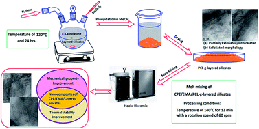
Nanocomposites of a chlorinated polyethylene (CPE)/ethylene methacrylate copolymer (EMA)/layered silicate were prepared by a direct melt blending technique and masterbatch process using two varieties of layered nanosilicates namely; polar Cloisite 30B with two hydroxyl groups in its organic modifier and non-polar Cloisite 20A. The first step was the synthesis of poly(ε-caprolactone) (PCL) grafted layered silicate masterbatch by covalent modification of in situ ring opening polymerization (ROP) of ε-caprolactone and subsequent characterization, followed by melt mixing of this layered silicate masterbatch into a CPE/EMA blend with a 60/40 ratio. A morphology study using wide angle X-ray diffraction (WXRD) and transmission electron microscopy (TEM) indicates complete exfoliation in the masterbatch PCL-g-30B and its nanocomposite (C60E40/PCL-g-30B). The addition of PCL-g-layered nanosilicate masterbatches with a higher degree of exfoliation, promoted the polymer–filler interaction as evident from Fourier transform infrared (FTIR) analysis which improved the static and dynamic mechanical properties and glass transition temperatures (Tg) of the nanocomposites. Fractography from scanning electron microscopy (SEM) images and topographical analysis using atomic force microscopy (AFM) clearly depicted improved filler dispersion in the PCL masterbatch based nanocomposites which also showed improved thermal stability to the CPE/EMA blend.

1. Introduction

Over the past more than two decades, polymer-organophilic layered silicate nanocomposites have attracted great interest from academics, industrialists, and different research laboratories.1–3 The successful preparation of a fully delaminated structure of layered silicates and their random dispersion in a polymer matrix leads to improved mechanical properties, thermal degradation stability, gas barrier properties and also flame resistance properties at very low loading of less than 10 wt% which further causes an added advantage of light weight.4–6 The high aspect ratio of individual nano-platelets of layered silicates having a width of 1 nm are ideal as a reinforcing nano-filler for polymers provided a very good interaction exists between the polymer and filler.4 Disintegrating the nanolayers from the silicate multilayer tactoids and dispersing them into polymers is not so easy due to their face-to-face stacking in highly agglomerated tactoids which are hydrophilic in nature.7 The inherent incompatibility of hydrophilic layered silicates in hydrophobic polymer matrix further hinders the delamination and dispersion of layered silicates.8 Modification of inorganic silicates with long chain organic cation lowers the surface energy and thereby improves the wetting with polymer matrix.9 In 1950, the Carter research group developed organo-modified clay with several organic onium ions (like aliphatic, aromatic amines; primary, secondary and tertiary amines; quaternary ammonium compounds and other onium compounds such as phosphonium) which effectively reinforced different elastomers.3 In 1960, Nahin and Stanley of Union Oil Co. patented organoclay composites of thermoplastic polyolefin and these composites have strong solvent resistance and improved tensile strength property.10 Hence, researchers were able to prepare polymer-layered silicate composites with improved filler–polymer interaction. However, Kojima and co-workers from Toyota research group developed a novel method of in situ ring opening polymerization (ROP) of ε-caprolactam for producing nylon 6-clay nanocomposites with improved strength, modulus, heat distortion temperature, and water and gas barrier properties.11 They reported high intercalation and exfoliation of layered silicates in the nylon 6 polymer matrix.12,13 Further, Giannelis and co-workers showed effective intercalation of polymer chains into galleries of layered silicates and thereby increased the interspace galleries and they reported it to occur spontaneously on melt mixing of polymers and layered silicates.14 Layered silicate based polymer nanocomposites are mainly prepared by two techniques: melt intercalation of preformed polymers and in situ intercalative polymerization. In the first method, the thermodynamics of melted polymer and the organomodified-silicates pair allows the macromolecular chains to penetrate into the silicate inter gallery spaces, and hence pushes the individual platelets apart one from each other.15 However, it is more difficult to prepare completely exfoliated polymer-silicate nanocomposite using melt blending technique. In the second method, the monomers swell the organomodified silicates by entering into its interlayer spacing and this is followed by in situ polymerization initiated by suitable initiator or catalyst. Chain growth inside the intergallery spacing makes the adjacent silicate platelets split apart from each other causing exfoliation and hence the polymerization reaction is the major driving force for nanocomposite formation.16 The ring opening polymerization of ε-caprolactone was catalyzed by tin alcoholate species generated in situ in the exchange reaction of tin(II) octoate with the hydroxyl groups of modifiers and of silicate layers as a initiator.17 The same research group Lepoittevin et al. in the later year reported to have successfully prepared partially exfoliated/intercalated PCL-layered silicate based nanocomposites by melt mixing technique.18

Chlorinated polyethylene (CPE) is an elastomer produced by random chlorination of high density polyethylene having excellent chemical resistance, flame resistance, oil resistance, mechanical property, and can be blended with different polymers to improve their properties. Reports are available for improving technical properties of CPE both by blending with other polymers or by incorporating suitable fillers in it. Basic studies on blends of CPE and EMA have already been published by our group and it was found to be technically well compatible in all compositions. Particularly, the 60/40 blend ratio of CPE/EMA showed better mechanical property, improved thermal stability, and finer morphology.19 Polymer-layered silicate nanocomposite opens up a huge opportunity to improve mechanical properties, thermal stability, and fire resistance properties of polymers provided with the condition of effective polymer–filler interaction and well dispersion of nanofillers in the matrix. Kim and White reported CPE/organomodified silicate composite where the macromolecular chains slightly intercalated in between the silicate layers.20 As CPE is reported to be compatible with PCL,21 hence a well intercalated and exfoliated PCL/layered silicate nanocomposites prepared by in situ polymerization by using the concept of “covalent modification” of layered silicate and it can be used as a “chemical masterbatch”. In that case, ε-caprolactone acts as a compatibilizer between CPE and silicate filler and thereby facilitates homogeneous dispersion of nanofillers and polymer–filler affinity.22,23 However, melt mixing of commercial PCL with organomodified MMT corresponds to the so-called “physical masterbatch” and it has inferior clay dispersion than “chemical masterbatch” approach.24 Moreover, Borah et al. reported the preferential choice of organophilic layered silicates to reside in the ethylene methacrylate (EMA) phase in LLDPE/EMA blends.25 To date, a thorough understanding on the correlation between all these factors like intercalation, complete exfoliation of clay by using many methods (covalent and non covalent modification) is a challenging task for novel applications. However, there have been no attempts to develop a hybrid materials based on covalent modification of layered silicate by using in situ ring opening polymerization of ε-caprolactone and incorporation of this into CPE/EMA blends for potential applications.

This paper presents the preparation of CPE/EMA blend nanocomposites of ratio 60/40 using two variety of commercially available organomodified layered silicate (Cloisite 20A and Cloisite 30B) for the first time. The method of nanocomposite preparation included both the in situ polymerization method and direct melt blending technique. The first step was the preparation of PCL-based organomodified layered silicate chemical masterbatch approach by using covalent modification concept which was followed by the melt mixing of the masterbatch with the polymer blend in order to achieve high degree of exfoliation and dispersion of clay in CPE/EMA blend matrix. WXRD and TEM studies were carried out to visualize the type and extent of clay dispersion in the CPE/EMA matrix. Fourier transform infrared (FTIR) attenuated total reflection (ATR) analysis of neat blend and its (nano)composites were also been carried out in order to investigate the polymer–filler interaction. Effect of different types of organomodified layered silicates (with and without PCL masterbatches) on mechanical properties of blend matrix was explored in terms of filler dispersion using SEM and AFM analysis. In addition, the physico-mechanical properties of the nanocomposites were evaluated to derive the structure–property correlation and to show the potential applications.

2. Experimental details

2.1. Materials

Commercial grade CPE elastomer (CPE 360) with 36% Cl content, having density of 1.213 g cm−3 with Mooney viscosity ML(1+4) at 121 °C of 65 ± 5 was obtained from East Corp International, India. Commercial grade of EMA, Elvaloy®1330 with 30% methyl acrylate (MA) content and a melt flow index (MFI) (at 190 °C/2.16 kg) of 3.0 g 10 min−1 (ASTM D1238) having melting point of 85 °C was obtained from NICCO Corporation, Shyamnagar, India. Nanoclays, Cloisite 20A is an organo-modified montmorillonite with dimethyl dehydrogenated tallow quaternary ammonium (2M2HT) chloride; and Cloisite 30B is organically modified with methyl tallow bis-2-hydroxyethyl quaternary ammonium (MHT2EtOH) chloride were purchased from Southern Clay Ltd., Mumbai, India. Stannous octoate (Sn(Oct)2) and the monomer ε-caprolactone were purchased from Sigma Aldrich. Magnesium oxide (MgO) of density 3.58 g cm−3 was used as acid scavenger for hydrochloric acid (HCl) produced during processing and molding. Dibutyltin dilaurate (DBTDL) and Irganox 1010 procured from Sigma Aldrich were used as heat stabilizer of CPE and as antioxidant, respectively.

2.2. In situ covalent modification of layered silicate (PCL-g-layered silicate masterbatches)

Poly(ε-caprolactone) (PCL) was covalently grafted on to the organomodified layered silicate surface by ring-opening polymerization (ROP) of ε-caprolactone in the presence of stannous octoate Sn(Oct)2 catalyst using coordination–insertion mechanism. In a typical reaction, the organo-modified layered silicates in a round bottom flask with magnetic bar were dried over night at 70 °C in vacuum. A given amount of ε-caprolactone (11 mL, 0.09 mol) was added to the layered silicates and the reaction mixer was put into a preheated oil bath at 120 °C under dry N2 atmosphere with continuous stirring at around 450 rpm. A toluene solution of Sn(Oct)2 (7 mL, 3.5 × 10⁻⁴ mol) was then added to the reaction mixer under inert atmosphere of nitrogen flow such that the [monomer]0/[Sn]0 molar ratio was 300. The polymerization was carried out at 120 °C for 24 h and stopped by temperature quenching. Then the polymer grafted with silicates in the reaction mixer was precipitated in methanol; whereas the unreacted monomers dissolved in methanol. The precipitated reaction product was dried in vacuum oven overnight at 50 °C. In both the cases, the masterbatches containing around 25 wt% of inorganics was targeted and the inorganic layered silicate content in each masterbatch was determined by thermo-gravimetric analysis (TGA). The prepared covalently modified chemical masterbatches samples are designated as: PCL-g-20A for poly(ε-caprolactone) grafted Cloisite 20A and PCL-g-30B for poly(ε-caprolactone) grafted Cloisite 30B, respectively.

2.3. Preparation of CPE/EMA/layered silicate (nano)composites

CPE/EMA/layered silicate nanocomposites were prepared by melt mixing technique in Haake Rheomix internal mixer operating at 140 °C for 12 min with a rotation speed of 60 rpm. CPE was first softened for 2 minutes along with MgO, DBTDL, and Irganox 1010. This was followed by addition of EMA copolymer and the mixing was continued for another 4 minutes. After that the layered silicate fillers or its masterbatches were added to the blend mix and the mixing was further continued for another 6 minutes. The collected samples were compression molded into 2 mm thick slabs. All prepared (nano)composites contained 3 wt% of inorganic layered silicates. The sample codes of the prepared CPE/EMA neat blend and its (nano)composites are mentioned in Table 1.
Table 1 Sample codes and its composition of neat CPE/EMA blend and its (nano)composites
Sample designationa CPE EMA Filler
a All other ingredient loadings (MgO, DBTDL, and Irganox 1010) are constant in each sample.
C60E40 60 40 0
C60E40/30B 60 40 3
C60E40/20A 60 40 3
C60E40/PCL-g-20A 60 40 3
C60E40/PCL-g-30B 60 40 3


2.4. Characterization

Fourier transform infrared (FTIR) spectroscopy studies were performed in order to confirm the successful synthesis of PCL and to inquire the presence of interaction between PCL and organo-modified layered silicates. The FTIR spectroscopy studies were performed on a Bruker Equinox 55 spectrophotometer, at a resolution of 0.5 cm−1, in the range of 4000–400 cm−1, and 64 scans were averaged out for each spectrum. The attenuated total reflection (ATR) mode was employed for revealing the polymer–filler affinity. The molecular weights of the two PCL extracted from PCL-g-20A and PCL-g-30B masterbatches synthesized via in situ polymerization were determined by gel permeation chromatography (GPC) (Agilient 1260 Infinity GPC instrument) using THF as an eluent at a flow rate of 1 mL min−1 and narrow disperse polystyrene as a calibration standard. The polymer solutions were passed through three PLgel 10 μm MIXED-B columns (300 × 7.5 mm) connected in series, which were preceded by a PLgel 10 μm guard column (50 × 75 mm). A RI detector was used to record the signal. Before injecting the polymer solution into the GPC instrument, it was thoroughly filtered using a regenerated cellulose filter of pore size 0.2 μm. Wide angle X-ray diffraction (WXRD) study was carried out to examine the inter-gallery spacing of layered silicates in prepared (nano)composite samples. The measurements were performed on Philips PW-1710 X-ray diffractometer (Eindhoven, The Netherlands), with crystal monochromated CuKα radiation (λ = 1.54 Å) in the angular range of 1–10° (2θ). The bulk morphology of the prepared masterbatches and its (nano)composites were analyzed in transmission electron microscopy (TEM). The samples of masterbatches were prepared by drop casting of its solution in carbon coated copper grid. Whereas, (nano)composite samples were prepared by ultra cryomicrotomy using Leica Ultracut UCT, at around 30 °C below the glass transition temperature (Tg) of the compounds. JEOL-2100 electron microscope (Tokyo, Japan) having LaB6 filament and operating at an accelerating voltage of 200 kV was utilized to obtain the bright field images of all samples. For analyzing the physico-mechanical properties, the prepared (nano)composites were cut into dumbbell-shaped test specimens (type V) and conditioned at 23 ± 2 °C and 50 ± 5% relative humidity for not less than 24 hours prior to testing according to ASTM D638-08. The tensile testing was carried out according to ASTM D 412-98 in a Hioks–Hounsfield Universal Testing Machine (Test Equipment, Ltd., Surrey, England). The test samples were fixed in the fixture and were pulled apart at a cross-head speed of 500 mm min−1, at room temperature until its failure. Tensile strength of nanocomposite samples was calculated by the instrument dividing the load at break by the original minimum cross-sectional area. The result is expressed in the unit of megapascals (MPa).
image file: c4ra15723k-t1.tif

Dynamic mechanical properties of the neat CPE/EMA blend and its prepared (nano)composites were determined with the help of a Dynamic Mechanical Analyzer DMA Q800 (TA Instruments, Lukens Drive, Newcastle, Delaware). The measurements were done under tension mode in the temperature range from −75 °C to +100 °C at a heating rate of 3 °C min−1 with 0.1% strain and 1 Hz frequency. Morphological studies of the neat polymer blend and its prepared (nano)composites were carried out using a scanning electron microscope (SEM), (model ZEISS EVO 60, Carl ZEISS SMT, Germany), operating at 20 kV. For this, samples from compression molded sheets were cryo-fractured in liquid nitrogen. The samples were then dried in vacuum oven at 50 °C for 2 h. The dried samples were coated with gold and subsequently examined their morphology. The X-ray silicon mapping (EDX) of the hybrid composite materials was recorded on an Oxford EDX system attached to the microscope. The topographic images of all samples were acquired using an AFM (Agilent Technologies, model 5100) in intermittent contact mode, using a Silicon Cantilever (PPP-NCL, Nanosensors Inc. USA). Phase images were recorded simultaneously at the resonance frequency of the cantilever with a scan rate of 1 Hz and a resolution of 256 samples per line. This allowed the resolution of individual primary particle measurements. In order to check the bulk morphology of the prepared nanocomposites, the samples were sliced using ultra microtome machine. Scanning was done at 5 different positions of each sample and representative images have been displayed here. Thermal degradation study of neat blend and its (nano)composites were carried out using TGA STARe System, METTLER TOLEDO at a heating rate of 20 °C min−1 under nitrogen atmosphere over the temperature range of 35 °C to 600 °C.

3. Results and discussion

3.1. Characterization of in situ covalent modification of layered silicate (PCL-g-layered silicate masterbatches)

The masterbatches PCL-g-20A and PCL-g-30B were prepared by covalent surface modification of layered silicate following in situ ring opening polymerization of ε-caprolactone using stannous octoate as catalyst. First, the layered silicates were swelled by monomer in reactor and the reaction mixer was homogenized by stirring. The reaction was activated by adding catalyst stannous octoate to the reaction mixer at 120 °C. Here, the surface hydroxyl groups of silicate platelets and its organic modifiers act as initiator. The catalyst stannous octoate forms active complex sites with the hydroxyl groups of nanoclay surface or of organic modifier as illustrated in Fig. 1a.26,27 This complex which is attached to the layered silicate surface initiates the ring opening polymerization of ε-caprolactone present in the gallery spacing of silicate layers. The whole process is schematically represented in Fig. 1b. Depending upon the type of modifiers of the commercial nanosilicates, complete or partial exfoliation takes place. The polymerization starts from the active sites of silicate layer surface and the subsequent chain growth develops a thrust on the nanosilicate platelets and thereby pushes it apart. Availability of active sites in the gallery spacing and effective chain growth leads to exfoliation or intercalation of the layered silicates. There are two types of PCL chains in the prepared masterbatch; loosely bound PCL chains which get dissolved and can be removed by repeated washing with THF. Whereas, the other type of PCL chains are covalently grafted onto the nano-platelet surface and are not removable by washing with THF. FTIR analysis was carried out for the organomodified silicate (Cloisite 30B), PCL-layered silicate masterbatch, THF washed silicate masterbatch, and pure PCL as shown in Fig. 2. FTIR spectra of organo-modified layered silicates show some characteristic bands at 3633 and 3385 cm−1 attributed to O–H stretching for the silicate and water molecules respectively.28 A very intense peak at 1048 cm−1 owing of stretching vibration of Si–O–Si from silicate.29 However, the PCL-layered silicate masterbatch didn't show the characteristic band of aluminosilicates (3633 cm−1 for O–H stretching and 1048 cm−1 for Si–O–Si stretching) which is because the polymer has multiple bands in the same spectral range and by far PCL is attached in large content to clay surface.30 The appearance of a modest carbonyl peak in THF washed PCL-g-30B masterbatch at around 1725 cm−1 clearly indicates the presence of chemically or covalently grafted PCL chains on the layered silicate surface. Furthermore, the carbonyl peak of PCL-g-30B masterbatch present at lower wavenumber (1724 cm−1) than the carbonyl peak for pure PCL (1727 cm−1) refers to intermolecular interaction between C[double bond, length as m-dash]O group of PCL chains and the OH group of layered silicates. Hence, existence of polymer–filler interaction is observed in the PCL-g-30B chemical masterbatch which is also found in the case of PCL-g-20A chemical masterbatch (ESI). Yield of PCL polymer was determined gravimetrically and was found to be close of 93%. It is found that under the same reaction condition, PCL polymer extracted from PCL-g-30B masterbatch have comparatively lower molecular weight and PDI value.18,22 The WXRD results and TEM images for these masterbatches are shown in Fig. 3a–d respectively. In the WXRD results of Fig. 3a and b, the basal plane d(001) diffraction peak for Cloisite 20A and Cloisite 30B were observed at 2θ region of 3.2° and 4.5° respectively. This basal plane of Cloisite 20A with d-spacing of 2.8 nm shifted to 2θ region of 2.8° with the increased d-spacing of 3 nm along with reduced peak intensity in case of PCL-g-20A. Similarly, in Fig. 3b the d(001) diffraction peak of Cloisite 30B that was observed at 2θ region of 4.56° with the d-spacing of 1.9 nm which was shifted to lower 2θ region of 2.1° with d-spacing of 4.2 nm for PCL-g-30B masterbatch. Though the inorganic clay content in the masterbatches is high (ca. 25 wt%), still a partially exfoliated and well intercalated layered silicate dispersion was observed in case of PCL-g-30B and PCL-g-20A respectively. In case of PCL-g-20A in Fig. 3c, though some exfoliated morphology was found but intercalated morphology prevailed. Whereas, Fig. 3d showed TEM morphology of PCL-g-30B masterbatch with partial exfoliation causing individual silicate layers moving apart from each other in different direction. The d(001) space was calculated from image analysis with Image J® software by thresholding of TEM images of both the masterbatches (representative images are shown in ESI Fig. S3 and S4) corroborates with the obtained WXRD results.
image file: c4ra15723k-f1.tif
Fig. 1 Schematic illustration of (a) formation of active sites for ring-opening polymerization (ROP) on the layered silicate surface and (b) intercalation and exfoliation during in situ polymerization.

image file: c4ra15723k-f2.tif
Fig. 2 FTIR spectra of (a) Cloisite 30B, (b) THF washed PCL-g-30B (c) PCL-g-30B masterbatch and (d) pure PCL polymer.

image file: c4ra15723k-f3.tif
Fig. 3 (a) WXRD patterns of Cloisite 20A and PCL-g-20A masterbatch, (b) Cloisite 30B and PCL-g-30B masterbatches; (c) TEM images of PCL-g-20A masterbatch and (d) PCL-g-30B masterbatches.

3.2. Characterization of C60E40/layered silicate (nano)composites

3.2.1. Morphology of nanocomposites. Morphology of all prepared (nano)composites was studied in order to find the state of dispersion of layered silicate platelets in the polymer matrix which is the most important factor for dictating mechanical properties of nanocomposites. The WXRD pattern of the nano(composites) with 3 wt% of inorganic content are presented in Fig. 4. The WXRD graphs of Cloisite 20A and Cloisite 30B exhibited intensive peaks at around 2θ = 3.2° and 2θ = 4.5° corresponding to a basal plane spacing d(001) of 2.8 nm and 1.9 nm. The pattern of the (nano)composites C60E40/20A, C60E40/PCL-g-20A, and C60E40/30B has a diffraction peak at around 2θ region of 2.7, 2.5, and 3.8, respectively whilst no diffraction peak was observed in case of C60E40/PCL-g-30B.
image file: c4ra15723k-f4.tif
Fig. 4 WXRD patterns of (a) C60E40/20A and C60E40/PCL-g-20A nanocomposites and (b) C60E40/30B and C60E40/PCL-g-30B masterbatches (with 3 wt% inorganic content).

The Table 2 shows the d-spacing of d(001) diffraction peak of all prepared (nano)composites with 3 wt% layered silicate loadings. The increased d-spacing of C60E40/PCL-g-20A to an appreciable level over the pristine Cloisite 20A; and disappearance of d(001) diffraction peak in C60E40/PCL-g-30B clearly indicates a successful and effective partial intercalation/exfoliation and complete exfoliation of Cloisite 20A and Cloisite 30B, respectively by the covalently grafted PCL chains on it. The WXRD results are in consistence with the TEM images in Fig. 5 taken from 10 different areas of the ultramicrotomed samples of each (nano)composites. All images were taken in same scale of 50 nm in order for comparison. In the Fig. 5a, the Cloisite 30B in C60E40 matrix shows a clear aggregation of nanosilicate layers with minor intercalation morphology. Whereas, in Fig. 5b, there are disintegrated nanosilicate stacks with lesser number of platelets were found to be well dispersed in different areas as shown with arrow marks in the C60E40/20A (nano)composite. In case of C60E40/PCL-g-20A in Fig. 5c, partial exfoliation and intercalation was observed whereas, completely exfoliated nanoplatelet structures were observed for C60E40/PCL-g-30B nanocomposite and these were well dispersed throughout the matrix as indicated with arrow marks in Fig. 5d. The silanol surface hydroxyl groups of silicate platelets of Cloisite 20A and both the surface hydroxyl group and OH group of organo-modifier in Cloisite 30B acted as co-initiator for the ring opening polymerization (ROP) of ε-caprolactone. The in situ ROP of ε-caprolactone from the platelet surface of gallery increased the interlaminar spacing. Effective PCL chain growth inside the gallery resulted exfoliation of nano-platelets in PCL-g-30B (clearly visible in Fig. 3c and d). Furthermore, the rigorous mechanical shearing action encountered during melt mixing in the highly viscous polymer melt has a tremendous effect in peeling off the loosened nanoplatelets from its stake in masterbatches. Hence, it is clear from the morphological observation that in situ covalent grafting of commercially available organo-modified layered silicates ensue effective intercalation and exfoliation in CPE/EMA matrix.

Table 2 The 2θ and corresponding d-spacing of d(001) basal plane of layered silicate (nano)composites from XRD analysis
Samples 2θ (degree) d-spacing (d001)
C60E40/20A 2.75 3.31
C60E40/PCL-g-20A 2.52 3.5
C60E40/30B 3.83 2.43
C60E40/PCL-g-30B Absent


image file: c4ra15723k-f5.tif
Fig. 5 TEM images of (a) C60E40/30B, (b) C60E40/20A, (c) C60E40/PCL-g-20A, and (d) C60E40/PCL-g-30B (nano)composites.
3.2.2. Polymer–filler interaction: thermodynamic aspect. The polymer–filler interaction is very important facet in the field of nanocomposite preparation. An appreciable level of polymer–filler interaction favors good dispersion, good interfacial adhesion and distribution in the polymer matrix. To the better understanding of interaction or interfacial adhesion between polymer matrix and fillers, Fowkes' equation was employed for this study. Fowkes' equation relates the change in IR peak position with enthalpy of interaction between the two systems.31 Fowkes' equation mainly deals with thermodynamic free energy of mixing and is presented as follows:
 
image file: c4ra15723k-t2.tif(1)
where, ΔH is enthalpy of interaction between the phases in the binary system (nanocomposites), and Δ[small nu, Greek, macron] is shift in peak position (corresponding to a functional or reactive group of the polymer that is involved in interactions). From the thermodynamic point of view, the total change of free energy of mixing in nanocomposites can be given as:
 
ΔGs = ΔHsTΔSs (2)

Hence, the change in free energy (which must be negative for a thermodynamically favorable process) is composed of an enthalpic term ΔHs and an entropic term ΔSs of the system. A negative enthalpy ΔHs leads to negative free energy of mixing which can be calculated from eqn (1). FTIR-ATR tool was adopted for determining the change in ΔHs during nanocomposite preparation and also in exploring the polymer blend miscibility involving dipole–dipole or hydrogen bond type interaction.32–34 It is well proven that a shift of the IR peaks towards lower wavenumber in the nanocomposites correspond to a negative value of ΔHs. This principal has been used by several researches to have an insight of thermodynamic feasibility of prepared (nano)composites.29,35–37 Fig. 6 shows FTIR-ATR spectra of neat CPE/EMA blend and its (nano)composites for comparison. The typical absorption peak for carbonyl (C[double bond, length as m-dash]O) stretching vibration observed at 1730 cm−1 in neat blend matrix shifted by approximately ∼7 cm−1 towards the lower wavenumber side in case of (nano)composites. A distinct peak shifting in associated with peak broadening effect is visible in nanocomposite samples which may be because of intermolecular hydrogen bond between the surface hydroxyl (OH) functional groups of layered silicates and carbonyl (C[double bond, length as m-dash]O) group from acrylate group of EMA copolymer. The characteristic C–Cl stretching peak from CPE was observed at around 700 cm−1 for neat CPE/EMA blend.38,39 A shifting of C–Cl stretching peak towards lower wavenumber in (nano)composites indicate that some interaction must have taken place between the polymer matrix and layered silicate through this group. The C–Cl peak shifting could be due to the involvement of specific intermolecular interaction between methine hydrogen of –CHCl or directly the C–Cl functional group of CPE with hydroxyl (OH) groups of filler.40 Table 3 displays the change in enthalpy values of nanocomposites where it is found that the ΔHs values are remarkably lower for PCL-layered silicate masterbatch based nanocomposites than the (nano)composites prepared by direct melt mixing of commercial layered silicates. The massive exfoliation transformed the layered silicates into individual silicate platelets in the respective nanocomposites which further increased the proximity of hydroxyl (OH) functional groups of filler with the carbonyl (C[double bond, length as m-dash]O) and C–Cl functional groups of polymer matrix.


image file: c4ra15723k-f6.tif
Fig. 6 FTIR-ATR spectra of neat CPE/EMA blend and its (nano)composites.
Table 3 Comparison of Enthalpy and its energy calculation for the prepared (nano)composites
Sample designation Peak position of C[double bond, length as m-dash]O stretching, cm−1 Δ[small nu, Greek, macron] of C[double bond, length as m-dash]O, cm−1 Peak position of C–Cl stretching, cm−1 Δ[small nu, Greek, macron] of C–Cl, cm−1 ΔH, kcal mol−1 for C[double bond, length as m-dash]O, cm−1 ΔH, kcal mol−1 for C–Cl, cm−1
C60E40 1730.76 700.71 0 0
C60E40/30B 1728.10 2.66 700.40 0.31 −0.627 −0.073
C60E40/20A 1727.29 2.71 698.09 2.62 −0.639 −0.618
C60E40/PCL-g-20A 1725.14 5.62 697.95 2.76 −1.326 −0.651
C60E40/PCL-g-30B 1723.12 7.64 696.05 4.66 −1.803 −1.099


3.2.3. Mechanical properties. In order to assess the macroscopic effect of different organically modified layered silicates with and without grafting PCL on the CPE/EMA blend matrix, formation of good interface, polymer–filler affinity and also to derive the structure–property relationship; tensile tests were carried out. Fig. 7 reports the mechanical properties of prepared neat CPE/EMA blend and its (nano)composites. It is observable from the Fig. 7a that addition of Cloisite 30B as such to CPE/EMA blend by direct melt blending technique reduced the tensile strength. This is because of the existence of large aggregates of layered silicates in micron size as evident from its TEM micrographs which acted as stress raiser. The existence of large aggregates of layered silicates in the polymer matrix is because of its poor hydrophobicity. But the (nano)composites prepared by direct melt blending of Cloisite 20A to polymer matrix increased the tensile strength value by 8.85% at the cost of its elongation at break. This improvement in tensile property of C60E40/20A, which is inconspicuous in C60E40/30B is due to high interlaminar gap in long chain organo-modified MMT (Cloisite 20A) that favored intercalation of polymer chains into the gallery spacing of layered silicates and thereby causing reinforcement. Nevertheless, the direct melt mixing of tiny amount of organo-modified layered silicates (3 wt%) which is much stiffer than polymer matrix led to increase of material stiffness.24,41 Interestingly, the addition of PCL-g-20A and PCL-g-30B to polymer matrix caused appreciable improvement in tensile strength by 21.69% and 29.18%, respectively with marginal decrease in (%) elongation at break. The reason can be explained on the basis of two antagonistic effect of reinforcing action of well dispersed fully exfoliated and intercalated layered silicates in polymer matrix and plasticization effect of PCL molecules.22 The partially intercalated and exfoliated masterbatches are getting well dispersed in the polymer matrix during melt mixing which has an obvious effect on increasing ultimate tensile strength. The improvement in ultimate mechanical performances which are governed by the dispersion and/or the exfoliation of nanoparticles in the polymer matrix is due mainly to the nanosize dimensions of fillers (as this results in an extremely large aspect ratio).7 Also, the strong polymer–filler interactions may influence the effectiveness of applied load transfer between nanofillers and the polymer matrix. Though the PCL chains have plasticizing effect which tends to increase (%) elongation at break, but in this case the reinforcing action of nano-layered silicate predominates. Among the masterbatch based nanocomposites, C60E40/PCL-g-30B nanocomposite is showing the highest tensile strength and modulus at 100% elongation. This is also because of the fully exfoliated individual nanosilicate platelets that are well dispersed all around the matrix accompanied by improved polymer–filler interaction (as was discussed with thermodynamic interpretation). Hence the nanofiller reinforcement overshadowed the plasticization effect of PCL chains. Moreover, nanocomposites prepared by PCL grafted masterbatch approach triggered much increase in modulus at 100% compared to (nano)composites prepared by direct melt blending of commercial organo-modified layered silicates with polymer as shown in Fig. 7b.15 Clearly, CPE/EMA nanocomposites prepared by the PCL-g-30B (covalent modification) approach display superior mechanical properties (material stiffness) compared to (nano)composites prepared by direct melt blending of organo-modified layered silicates. Hence, it can be inferred that due to effective covalent grafting of layered silicates by organic PCL chains (organophilization) and high degree of intercalation and/or exfoliation, the masterbatch based nanocomposites (i.e. PCL-g-20A and PCL-g-30B) showed considerable increment in mechanical properties. Overall, the key factors behind the significant improvements in mechanical properties are: covalent surface modification of the layered silicates, polymer–filler affinity, and high degree of exfoliation.
image file: c4ra15723k-f7.tif
Fig. 7 Mechanical properties (a) tensile strength, (b) modulus at 100% elongation and (c) elongation at break (%) of C60E40 blend and its (nano)composites.
3.2.4. Dynamic mechanical analysis (DMA). The DMA results are very helpful to evaluate several parameters to find the effect of organo-modified and PCL-modified layered silicates on the blend matrix. Fig. 8a and b displays the temperature dependence of tan[thin space (1/6-em)]δ and storage modulus E′ of neat polymer blend and their (nano)composites over a temperature range of −75 °C to 100 °C, respectively. Table 4 summarizes the variation in glass transition temperature (Tg) which is the temperature of the maximum of tan[thin space (1/6-em)]δ of the blend matrix with respect to addition of different types of organo-modified and PCL-modified layered silicates along with their storage modulus (E′) values. In this case from the Table 4, it is found that the Tg value of (nano)composite did not cause any significant change on addition of commercial organo-modified nanosilicates Cloisite 20A and Cloisite 30B as also reported in literatures.42,43 But an appreciable shift of tan[thin space (1/6-em)]δ peak towards higher temperature is observed in case of C60E40/PCL-g-20A and C60E40/PCL-g-30B nanocomposites. Among these two PCL grafted layered silicate chemical masterbatch based nanocomposites, C60E40/PCL-g-30B is showing highest shifting of Tg. The successful and effective covalent grafting of organic PCL chains on the layered silicate surface (as evident from the FTIR analysis) improved polymer–filler interaction which restricted larger number of chains of the polymer matrix. In addition to that, the high degree of exfoliation in the aforesaid masterbatch (as discussed in the morphology of masterbatches) resulted better dispersion of layered silicates in nanometer scale in the polymer matrix which further increased the material stiffness.44,45 All (nano)composites has undergone a clear broadening of tan[thin space (1/6-em)]δ peak over neat polymer matrix. The damping (height of the tan[thin space (1/6-em)]δ peak) indicates the ability of the material for dissipating the applied energy and at Tg region the long range macromolecular chains attain mobility by dissipating energy through viscous movement.46 Decreasing the height of tan[thin space (1/6-em)]δ peak means reduction of number of mobile macromolecular chains in its transition region. The improved interfacial adhesion between the silicate layers and polymer matrix due to exfoliation and intercalation of covalently grafted layered silicates (PCL-g-layered silicates) caused formation of immobilized region around the silicate surface.2 Fig. 8b shows the evolution of the storage modulus as a function of temperature for C60E40 neat blend and its (nano)composites. These curves indicates that the storage modulus of (nano)composites at low temperature (−75 °C) below the Tg is clearly much higher than the neat polymer blend and their values are enlisted in Table 4.
image file: c4ra15723k-f8.tif
Fig. 8 Temperature sweep of (a) tan[thin space (1/6-em)]δ and (b) storage modulus (E′) of neat polymer blend and its (nano)composites.
Table 4 Glass transition temperature (Tg) and storage modulus (E′) of all samples from DMA analysis
Sample designations Glass transition temperature Tga (°C) Storage modulus E′ at −75 °C (MPa)
a The glass transition temperatures for all samples are taken from the tan[thin space (1/6-em)]δ vs. temperature plot of DMA.
C60E40 5.2 2720
C60E40/30B 5.3 3132
C60E40/20A 5.9 3785
C60E40/PCL-g-20A 7.4 3892
C60E40/PCL-g-30B 9.2 4300


It is worth to mention that storage modulus below the glass transition temperature is primarily dictated by the strength of intermolecular forces existing between polymer–filler and the way polymer chains are packed.47 The improved storage modulus of all (nano)composites over neat polymer is attributed to better polymer–filler interaction and improved dispersion of nano-sized layered silicate platelets in the polymer matrix. Further, the nanocomposite C60E40/PCL-g-30B has highest storage modulus among all other (nano)composites which is again because of complete exfoliation of nanosilicate platelets and good polymer–filler interaction.

3.2.5. Fractography of CPE/EMA (nano)composites. In order to characterize the bulk structure attributes, the cryo-fractured surface morphology of the neat CPE/EMA blend and its nanocomposites were analyzed using scanning electron microscopy. The low magnification SEM images in Fig. 9 show the overall view of fractured surface morphology of pure CPE/EMA blend and its nanocomposites with 3 wt% layered silicate loading. From the Fig. 9a it can be seen that the neat CPE/EMA blend has smooth surface morphology hinting its poorer resistance towards crack propagation.48,49
image file: c4ra15723k-f9.tif
Fig. 9 (a) SEM images of fractured surface morphology of pure C60E40 blend, (b) C60E40/30B, (c) C60E40/20A, (d) C60E40/PCL-g-20A, and (e) C60E40/PCL-g-30B (nano)composites; and (w) Silicon dot element analysis of C60E40/30B, (x) C60E40/20A, (y) C60E40/PCL-g-20A, and (z) C60E40/PCL-g-30B (nano)composites by SEM.

On the contrary, the (nano)composites are found to have totally different fractured surface morphology from the neat blend. The fractured surface of CPE/EMA/PCL-g-20A and CPE/EMA/PCL-g-30B is very rough with a good deal of ridgelines which indicates the direction of crack propagation along the polymer–filler interface. Such rough surface morphology along with the ridgelines as shown by blue colored arrows in Fig. 9d and e, indicate good polymer–filler interaction between the polymer matrix and silicate layers with better dispersion which may again be related to the improvement in mechanical properties.50 On the other hand, no crack initiation or propagation is observed in case of organo-modified layered silicates (CPE/EMA/30B and CPE/EMA/20A) (nano)composites revealing a simple pull out of silicate aggregates highlighted with blue colored circles in Fig. 9b and c from the polymer matrix. A comparatively smoother fracture surface of these (nano)composites usually indicates for poor polymer–filler affinity accompanied with premature, rather brittle type fracture.51 Such weak interfacial polymer–filler adhesion leads to poor dispersion and inefficient stress transfer which accounts for inferior mechanical properties. The dispersion of the layered silicates is confirmed by SEM elemental dot mapping analysis as shown in Fig. 9w–z. The white dots represent the X-ray signals of silicon elements in the nanoclay particles. In Fig. 9w, it can be clearly seen that the nanocomposite with Cloisite 30B show larger agglomerates in the polymer matrix, while the rest other nanocomposites (Fig. 9x–z) show almost uniform dispersion of nanoclay throughout the matrix. Since, the (nano)composite with Cloisite 20A has larger interlayer spacing (as observable from WXRD study of nanocomposites) and hence show better dispersion than (nano)composite with Cloisite 30B. On the other hand, the layered silicates with smaller interlayer spacing (Cloisite 30B) typically show conventional composite like structures.52

3.2.6. AFM-topographic analysis of CPE/EMA (nano)composites. The 3-D phase images of neat CPE/EMA blend and its (nano)composite samples are illustrated in Fig. 10a–e. Taking into consideration the difference in hardness of the two investigated polymer matrix, AFM phase images of all prepared samples showed clear two phases of polymers. The dark brown and light brown color represented CPE and EMA phases, respectively which may be due to the deeper penetration of the cantilever tip in the sample.53,54 In the neat blend of Fig. 10a, the light yellow colored mild projection is due to magnesium oxide used as acid scavenger. On the other hand, in case of filled samples, the yellow bright protruding features are the silicate layers. The AFM images here might not display the entire surface area for the platelets as these surfaces might have been buried in the polymer matrix.55 Moreover, in AFM the platelet size is found to be higher than observed from representative TEM micrographs which may be due to the tip broadening effect.54 From Fig. 10d and e it is clearly shown that layered silicates are well dispersed in the polymer matrix in case of nanocomposites prepared by masterbatch process. Whereas, the (nano)composite C60E40/30B showed poor dispersion in associated with aggregation of layered silicates in Fig. 10b and these results clearly corroborates the SEM results and morphology study of (nano)composites which we discussed in the earlier section. Similar observation is made when a large number of areas were analyzed at different magnifications.
image file: c4ra15723k-f10.tif
Fig. 10 AFM 3-D phase images of (a) neat C60E40 blend and (b) C60E40/30B, (c) C60E40/20A, (d) C60E40/PCL-g-20A, and (e) C60E40/PCL-g-30B (nano) composites.
3.2.7. Thermal stability of the nano(composites). Addition of organo-modified layered silicates into polymer matrix has both positive and adverse effect on its thermal degradation stability. Based on the chemical nature of polymer matrix, polymer–filler interaction, morphology of layered silicates inside the matrix; nanocomposites may show improved or inferior thermal stability over neat blend. In order to investigate the effect of Cloisite 20A, Cloisite 30B and their PCL grafted masterbatches on the thermal stability of CPE/EMA blend, TGA study has been carried out in inert atmosphere of N2. The thermo-gravimetrograms of neat C60E40 blend and its (nano)composites are plotted in Fig. 11. From the TGA plot, the onset degradation temperature Ti, (corresponding to 5 wt% loss) and T50 (temperature corresponding to 50 wt% loss) along with their residue content (wt%) were tabulated in Table 5. It can be seen from the Fig. 11 that addition of commercially available organo-modified layered nanosilicates (Cloisite 20A and Cloisite 30B) as such into the polymer matrix decreased Ti and T50 values which is similar to previously reported numerous literatures.56–58 This reduced thermal stability of C60E40/20A and C60E40/30B (nano)composites over neat polymer blend can be explained on the ground of significant catalytic activity of metallic derivatives released from silicate interlayer spaces. In addition to that, the organic modifiers of layered silicates are less thermally stable than the neat polymer. Interestingly, this adverse affect of layered silicates on the thermal degradation stability of C60E40 blend is overcome by the adopted PCL-layered silicate masterbatch process. These PCL-layered silicate masterbatch based nanocomposites are more thermally stable than the (nano)composites prepared by direct melt mixing of Cloisite 20A and Cloisite 30B and even neat polymer blend matrix. The reason can be attributed to the quality of dispersion of layered silicates and covalent modification. It is abundantly reported that exfoliated structure leads to higher thermal stability than intercalated or conventional microcomposite structures.59,60 Besides, improved polymer–filler interaction helps the individual layered silicate platelets to disperse homogeneously and randomly in nano level within the matrix. In our study, the covalently modified layered silicate nanocomposites have extensively intercalated and exfoliated morphology. The homogeneous dispersion of nano-platelets in the masterbatch based nanocomposites (as evident from TEM micrographs) not only improved mechanical properties but also acted as a mass transport barrier hindering the volatilization of decomposed gaseous products during degradation. The hindrance effect of layered silicates take place due to the formation of char layers formed via collapsing the nanocomposite structure during degradation. Furthermore, the C60E40/PCL-g-30B nanocomposite showed even higher thermal stability than the C60E40/PCL-g-20A nanocomposite as shown in Table 5. The reason can be explained on the basis of fully exfoliated morphology of C60E40/PCL-g-30B whereas; the later has partially intercalated-exfoliated morphology. The fully exfoliated layered silicate can promote char formation under degradation, which can act as physical barrier (Labyrinth effect) to the volatile products generated during decomposition. Hence, melt mixing of covalently modified PCL-layered silicate with C60E40 blend is an effective way to develop nanocomposites with superior mechanical properties with improved thermal stability.
image file: c4ra15723k-f11.tif
Fig. 11 TGA plots of neat C60E40 blend and their (nano)composites.
Table 5 TGA data of neat C60E40 blend and its prepared (nano)compositesa
Sample designations Ti (°C) T50 (°C) Residue content (wt%)
a Ti is the temperature at 5% weight loss and T50 is the temperature at 50% weight loss.
C60E40 293.2 474.7 11.15
C60E40/20A 285.6 473.3 14.29
C60E40/30B 288.3 467.7 14.24
C60E40/PCL-g-20A 300.0 480.0 14.52
C60E40/PCL-g-30B 313.57 482.2 15.02


4. Conclusions

CPE/EMA/layered silicate (nano)composites were prepared by two methods: direct melt mixing of commercial organo-modified layered silicates (Cloisite 20A and Cloisite 30B) and by novel PCL-layered silicate masterbatch approach. In the chemical masterbatch approach, first step was covalent modification of layered silicates by in situ ring opening polymerization of ε-caprolactone. In the second step, these masterbatches were then melt blended with CPE/EMA blend matrix such that the final silicate content was 3 wt%. Unlike the direct melt blended (nano)composites where lightly intercalated morphologies predominate all over the matrix, this two-step preparation of PCL-based CPE/EMA nanocomposites led to largely exfoliated morphology. Significant synergism was observed in the mechanical properties of PCL-layered silicate based nanocomposites with little loss of % elongation at break. Furthermore, among the masterbatch based nanocomposites, PCL-g-30B showed highest mechanical properties because of complete exfoliation of layered silicates into nano-platelets with maximum polymer–filler interaction. From the FTIR analysis and DMA storage modulus (E′) data it is believed that the randomly dispersed exfoliated nanosilicate platelets and covalent modification increased the probability for polymer–filler interaction. The SEM and AFM study also corroborates the XRD and TEM results in morphology analysis. The thermal degradation stability of PCL-g-30B nanocomposite is found to be higher than any other (nano)composites which is because of higher degree of exfoliation and dispersion of layered silicates along with improved polymer–filler interaction. Such increment in mechanical properties along with improved thermal degradation stability of exfoliated layered silicate masterbatch with CPE/EMA blend by commercial melt blending can have enormous positive impact on many applications such as electrical power cables, hose, pipe, and under the hood applications.

References

  1. N. Ogata, G. Jimenez, H. Kawai and T. Ogihara, J. Polym. Sci., Part B: Polym. Phys., 1997, 35, 389–396 CrossRef CAS.
  2. P. B. Messersmith and E. P. Giannelis, Chem. Mater., 1994, 6, 1719–1725 CrossRef CAS.
  3. L. W. Carter, J. G. Hendricks and D. S. Bolley, Elastomer reinforced with a modified clay, US Pat., US2531396 A, 1950.
  4. C. Wan, X. Qiao, Y. Zhang and Y. Zhang, Polym. Test., 2003, 22, 453–461 CrossRef CAS.
  5. J. W. Gilman, Appl. Clay Sci., 1999, 15, 31–49 CrossRef CAS.
  6. O. Gain, E. Espuche, E. Pollet, M. Alexandre and P. Dubois, J. Polym. Sci., Part B: Polym. Phys., 2005, 43, 205–214 CrossRef CAS PubMed.
  7. V. Mittal, Optimization of polymer nanocomposite properties, John Wiley & Sons, 2009 Search PubMed.
  8. M. Kurian, A. Dasgupta, F. L. Beyer and M. E. Galvin, J. Polym. Sci., Part B: Polym. Phys., 2004, 42, 4075–4083 CrossRef CAS PubMed.
  9. P. Kiliaris and C. D. Papaspyrides, Prog. Polym. Sci., 2010, 35, 902–958 CrossRef CAS PubMed.
  10. P. G. Nahin and B. P. Stanley, Organoclay–polyolefin compositions, US Pat., US3084117 A, 1963.
  11. Y. Kojima, A. Usuki, M. Kawasumi, A. Okada, Y. Fukushima, T. Kurauchi and O. Kamigaito, J. Mater. Res., 1993, 8, 1185–1189 CrossRef CAS.
  12. A. Usuki, Y. Kojima, M. Kawasumi, A. Okada, Y. Fukushima, T. Kurauchi and O. Kamigaito, J. Mater. Res., 1993, 8, 1179–1184 CrossRef CAS.
  13. Y. Kojima, A. Usuki, M. Kawasumi, A. Okada, T. Kurauchi and O. Kamigaito, J. Polym. Sci., Part A: Polym. Chem., 1993, 31, 983–986 CrossRef CAS PubMed.
  14. R. A. Vaia, H. Ishii and E. P. Giannelis, Chem. Mater., 1993, 5, 1694–1696 CrossRef CAS.
  15. B. Lepoittevin, N. Pantoustier, M. Devalckenaere, M. Alexandre, C. Calberg, R. Jérôme, C. Henrist, A. Rulmont and P. Dubois, Polymer, 2003, 44, 2033–2040 CrossRef CAS.
  16. T. Lan, P. D. Kaviratna and T. J. Pinnavaia, Chem. Mater., 1995, 7, 2144–2150 CrossRef CAS.
  17. B. Lepoittevin, N. Pantoustier, M. Devalckenaere, M. Alexandre, D. Kubies, C. Calberg, R. Jérôme and P. Dubois, Macromolecules, 2002, 35, 8385–8390 CrossRef CAS.
  18. B. Lepoittevin, M. Devalckenaere, N. Pantoustier, M. Alexandre, D. Kubies, C. Calberg, R. Jérôme and P. Dubois, Polymer, 2002, 43, 4017–4023 CrossRef CAS.
  19. P. Bhagabati and T. K. Chaki, J. Appl. Polym. Sci., 2014, 131, 11 CrossRef PubMed.
  20. Y. Kim and J. L. White, J. Appl. Polym. Sci., 2003, 90, 1581–1588 CrossRef CAS PubMed.
  21. T. S. Plivelic, S. N. Cassu, M. do Carmo Gonçalves and I. L. Torriani, Macromolecules, 2006, 40, 253–264 CrossRef.
  22. S. Benali, S. Peeterbroeck, P. Brocorens, F. Monteverde, L. Bonnaud, M. Alexandre, R. Lazzaroni and P. Dubois, Eur. Polym. J., 2008, 44, 1673–1685 CrossRef CAS PubMed.
  23. P. Brocorens, S. Benali, C. Broekaert, F. Monteverde, H. E. Miltner, B. Van Mele, M. Alexandre, P. Dubois and R. Lazzaroni, Langmuir, 2008, 24, 2072–2080 CrossRef CAS PubMed.
  24. C. Broekaert, S. Peeterbroeck, S. Benali, F. Monteverde, L. Bonnaud, M. Alexandre and P. Dubois, Eur. Polym. J., 2007, 43, 4160–4168 CrossRef CAS PubMed.
  25. J. S. Borah, N. Karak and T. K. Chaki, Mater. Sci. Eng., A, 2011, 528, 2820–2830 CrossRef PubMed.
  26. K. Majerska, A. Duda and S. Penczek, Macromol. Rapid Commun., 2000, 21, 1327–1332 CrossRef CAS.
  27. A. Kowalski, A. Duda and S. Penczek, Macromolecules, 2000, 33, 7359–7370 CrossRef CAS.
  28. P. Viville, R. Lazzaroni, E. Pollet, M. Alexandre, P. Dubois, G. Borcia and J.-J. Pireaux, Langmuir, 2003, 19, 9425–9433 CrossRef CAS.
  29. S. Anandhan, H. G. Patil and R. R. Babu, J. Mater. Sci., 2011, 46, 7423–7430 CrossRef CAS.
  30. P. C. LeBaron, Z. Wang and T. J. Pinnavaia, Appl. Clay Sci., 1999, 15, 11–29 CrossRef CAS.
  31. J. Zheng, R. Ozisik and R. W. Siegel, Polymer, 2005, 46, 10873–10882 CrossRef CAS PubMed.
  32. S. Shang, J. Williams and K.-J. Söderholm, J. Mater. Sci., 1994, 29, 2406–2416 CrossRef CAS.
  33. S. Peng, X. Wang and L. Dong, Polym. Compos., 2005, 26, 37–41 CrossRef CAS PubMed.
  34. P. Kundu, D. Tripathy and S. Banerjee, Polymer, 1996, 37, 2423–2431 CrossRef CAS.
  35. M. Selvakumar, S. K. Jaganathan, G. B. Nando and S. Chattopadhyay, J. Biomed. Nanotechnol., 2014, 10, 1–15 CrossRef PubMed.
  36. M. Kader and A. Bhowmick, Polym. Compos., 2001, 9, 263–275 CAS.
  37. M. Maiti and A. K. Bhowmick, J. Polym. Sci., Part B: Polym. Phys., 2006, 44, 162–176 CrossRef CAS PubMed.
  38. M. Coleman, E. Moskala, P. Painter, D. Walsh and S. Rostami, Polymer, 1983, 24, 1410–1414 CrossRef CAS.
  39. R. Chakrabarti and D. Chakraborty, J. Appl. Polym. Sci., 2007, 105, 1377–1384 CrossRef CAS PubMed.
  40. C. Li, S.-A. Xu, F.-Y. Xiao and C.-F. Wu, Eur. Polym. J., 2006, 42, 2507–2514 CrossRef CAS PubMed.
  41. N. González-Vidal, S. Muñoz-Guerra, A. Martínez de Ilarduya, S. Benali, S. Peeterbroeck and P. Dubois, Eur. Polym. J., 2010, 46, 156–164 CrossRef PubMed.
  42. R. Ollier, E. Rodriguez and V. Alvarez, Composites, Part A, 2013, 48, 137–143 CrossRef CAS PubMed.
  43. T. D. Ngo, M. T. Ton-That, S. V. Hoa and K. C. Cole, Polym. Eng. Sci., 2012, 52, 607–614 CAS.
  44. M. Eesaee and A. Shojaei, Composites, Part A, 2014, 63, 149–158 CrossRef CAS PubMed.
  45. M. A. Sawpan, P. G. Holdsworth and P. Renshaw, Mater. Des., 2012, 42, 272–278 CrossRef CAS PubMed.
  46. Y. Rao and J. M. Pochan, Macromolecules, 2006, 40, 290–296 CrossRef.
  47. L. A. Pothan, Z. Oommen and S. Thomas, Compos. Sci. Technol., 2003, 63, 283–293 CrossRef CAS.
  48. N. Dayma and B. K. Satapathy, Mater. Des., 2010, 31, 4693–4703 CrossRef CAS PubMed.
  49. M. Kotal, S. K. Srivastava and A. K. Bhowmick, Polym. Int., 2010, 59, 2–10 CrossRef CAS PubMed.
  50. A. Das, F. R. Costa, U. Wagenknecht and G. Heinrich, Eur. Polym. J., 2008, 44, 3456–3465 CrossRef CAS PubMed.
  51. P. L. Teh, Z. A. Mohd Ishak, A. S. Hashim, J. Karger-Kocsis and U. S. Ishiaku, Eur. Polym. J., 2004, 40, 2513–2521 CrossRef CAS PubMed.
  52. U. Sookyung, C. Nakason, W. Thaijaroen and N. Vennemann, Polym. Test., 2014, 33, 48–56 CrossRef CAS PubMed.
  53. H. H. Le, M. N. Sriharish, S. Henning, J. Klehm, M. Menzel, W. Frank, S. Wießner, A. Das, K. W. Stöckelhuber, G. Heinrich and H. J. Radusch, Compos. Sci. Technol., 2014, 90, 180–186 CrossRef CAS PubMed.
  54. M. Maiti and A. K. Bhowmick, Polymer, 2006, 47, 6156–6166 CrossRef CAS PubMed.
  55. A. J. Jose, M. Alagar and A. S. Aprem, Int. J. Polym. Mater., 2012, 61, 544–557 CrossRef CAS.
  56. C. Zhao, H. Qin, F. Gong, M. Feng, S. Zhang and M. Yang, Polym. Degrad. Stab., 2005, 87, 183–189 CrossRef CAS PubMed.
  57. J. W. Gilman, Appl. Clay Sci., 1999, 15, 31–49 CrossRef CAS.
  58. J. W. Cho and D. R. Paul, Polymer, 2001, 42, 1083–1094 CrossRef CAS.
  59. A. A. Vassiliou, K. Chrissafis and D. N. Bikiaris, Thermochim. Acta, 2010, 500, 21–29 CrossRef CAS PubMed.
  60. F.-C. Chiu, S.-W. Fu, W.-T. Chuang and H.-S. Sheu, Polymer, 2008, 49, 1015–1026 CrossRef CAS PubMed.

Footnote

Electronic supplementary information (ESI) available. See DOI: 10.1039/c4ra15723k

This journal is © The Royal Society of Chemistry 2015
Click here to see how this site uses Cookies. View our privacy policy here.