
Experimental realization of tunable negative permittivity in percolative Fe78Si9B13/epoxy composites
Qing Hou,
Ke-lan Yan,
Run-hua Fan*,
Zi-dong Zhang,
Min Chen,
Kai Sun and
Chuan-bing Cheng
Key Laboratory for Liquid–Solid Structural Evolution and Processing of Materials (Ministry of Education), Shandong University, Jinan, Shandong, China. E-mail: fan@sdu.edu.cn; Fax: +86 0531 88392315; Tel: +86 0531 88393396
First published on 5th January 2015
Abstract
Negative permittivity is one of the most important properties in the realization of double negative medium or negative index materials. In this paper, tunable negative permittivity in the radio frequency range has been obtained in composites with Fe78Si9B13 amorphous alloy dispersed in an epoxy matrix. The microstructure and dielectric properties of Fe78Si9B13/epoxy composites are investigated in detail. The results indicate that when the Fe78Si9B13 content is beyond the percolation threshold, the plasma oscillation of delocalized electrons in interconnected Fe78Si9B13 leads to negative permittivity. By controlling the effective concentration of free electrons, the negative permittivity of the Fe78Si9B13/epoxy composites could be easily adjusted. Additionally, the frequency dispersion behaviors of the conductivity conform to the Jonscher's power law below percolation threshold, demonstrating that the conductive mechanism is hopping conduction. The realization of tunable negative permittivity in Fe78Si9B13/epoxy composites gives a new and high-efficient way toward double negative materials.
Introduction
In the past decade, double negative materials (DNMs) with simultaneously negative permittivity ε and permeability μ have gained extensive research attention due to their novel potential applications in electronic, microwave and optical fields.1–3 The medium which had a negative refractive index was first proposed by Veselago theoretically in 1967.4 His finding remained an academic curiosity for a long time until 2001, the double negative property was successfully obtained in an artificial periodic metallic structure with arrays of split-ring resonators and wires by Smith et al.5 Soon afterwards, various metamaterials composed of arrays of unit cells with various novel structures were proposed to achieve negative permittivity and permeability.6,7It is well recognized that the double negative properties in metamaterials are originated by their special artificial structures, such as nonmagnetic split ring resonators and continuous wires,5 lithographically patterned inductive–capacitive resonator double-split-ring resonators,8 S-shaped resonators,9 rather than directly by the materials' nature. In all the artificial structures mentioned above, resonance was considered to be the main mechanism of the realization of the double negative property.10 In fact, it is also interesting to investigate the possibility of realizing the double negative property directly from the materials' intrinsic properties, rather than from periodic artificial structures. In our previous works, we successfully realized negative permittivity and permeability by using metal/ceramic composites with the construction of the random metallic networks hosted in ceramics, such as Ag/Al2O3, Ni/Al2O3.11–13 And soon after, the random composites for DNMs have attracted much attention and many percolative granular composites have been considered as DNMs by T. Tsutaoka et al.14,15 As conductor/insulator composites, the appearance of negative permittivity is the result of the plasma oscillation of conduction electrons provided by the metallic component occurred beyond but near percolation threshold. And the plasma frequency is determined by effective concentration of electrons. Insulating polymers like epoxy can also be the matrix as a substitute for ceramic on condition that the effective concentration of electrons is under control. The attractive properties of epoxy such as light-weight, chemical inertness, large-scale and machinability could be utilized for realizing truly practical applications which are not fully realized by ceramic materials.16
Cryomilling is a mechanical attrition technique in which powders are milled with milling balls and a cryogenic liquid.17 It is well known that, as a conventional technique to prepare fine powder mixtures, room temperature ball milling is not appropriate for the preparation of fine powders containing ductile metal component. Even over, the high energy release during ball milling may result in the reaction of the powders. Cryogenic temperature will embrittle the metal and restrain the mechanochemical reaction of original powders.18
In this paper, Fe78Si9B13/epoxy composites with different Fe78Si9B13 content have been fabricated by using cryomilling combined with hot press forming. The microstructure and electromagnetic properties of the Fe78Si9B13/epoxy composites are investigated. Interestingly, negative permittivity appeared in the composites when Fe78Si9B13 contents reach percolation threshold.
Experimental
In this paper, a commercially available Fe78Si9B13 powder was chosen to be electric component of the composites. For the homogenously dispersion of Fe78Si9B13 powder in epoxy, powders were cryomilled 20 r s−1 at liquid nitrogen temperature (−196 °C) for 5 min. Then the powder mixtures with Fe78Si9B13 volume fraction of 71%, 76%, 78%, and 83% were hot-pressed at 80 °C and 35 MPa to form the final round-shape samples with 22 mm in diameter and around 2 mm thick, and the Fe78Si9B13/epoxy composites were referred to as FSB71, FSB76, FSB78 and FSB83, respectively.The cryomilling was carried out by a cryomill (Retsch, Germany). The microstructure of bulks was investigated by X-ray diffraction (XRD) and SU-70 field emission scanning electron microscopy (FESEM). The impedance properties of the bulk Fe78Si9B13/epoxy composites were determined in the frequency range from 10 MHz to 1 GHz at room temperature, by using Agilent E4991A precision impedance analyzer (Agilent Technologies) equipped with 16453A dielectric test fixture. In order to determine the permittivity vs. frequency or various kinds of dielectric parameters, the dielectric test was under AC voltage 100 mV. During the measurement, the real part (ε′r) and imaginary part (ε′′r) of permittivity were then determined from the following formula,
 | (1) |
 | (2) |
Results and discussion
Fig. 1 shows the XRD patterns of the Fe78Si9B13 powder and Fe78Si9B13/epoxy composite. Two broad diffraction peaks reflecting amorphous structure were detected in the XRD patterns of every composite.19 | ||
| Fig. 1 (a) X-ray diffraction patterns of Fe78Si9B13 powder and (b) is the X-ray diffraction patterns of Fe78Si9B13/epoxy composite with different Fe78Si9B13 contents. | ||
The SEM images of Fe78Si9B13/epoxy composites (FSB71 and FSB83) are shown in Fig. 2. It can be observed that the Fe78Si9B13 distributed uniformly within the resin matrix cryomilled just 5 min (Fig. 2(a) and (c)). In addition the Fe78Si9B13 combined with resin closely (Fig. 2(b) and (d)).
 | ||
| Fig. 2 SEM images of Fe78Si9B13/epoxy composite of different Fe78Si9B13 contents (a and b) FSB71 (c and d) FSB83. | ||
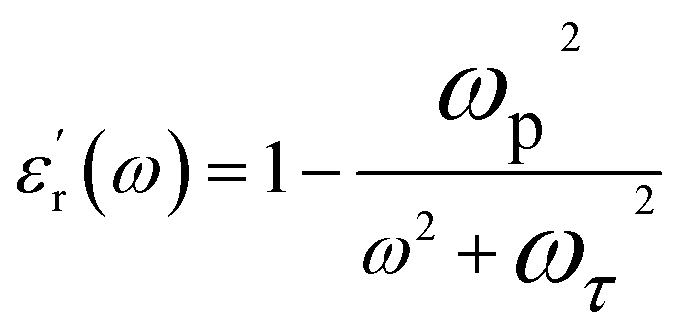
The dielectric spectra of Fe78Si9B13/epoxy composite with different Fe78Si9B13 contents are presented in Fig. 3. For samples FSB71 and FSB76, the real part of permittivity ε′r is positive and decreases as the frequency vary from 10 MHz to 1 GHz. Further increasing the Fe78Si9B13 content result in the appearance of negative ε′r throughout the whole test frequency range in FSB78 and FSB83.
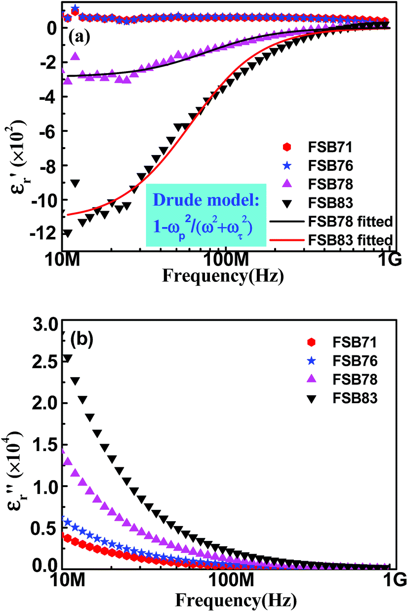 | ||
| Fig. 3 Dielectric spectra of Fe78Si9B13/epoxy composite (a) the real permittivity (the dielectric dispersion can be fitted by Drude model for FSB78 and FSB83), (b) the imaginary permittivity. | ||
Theoretically, the negative permittivity for composites is realized by the plasma oscillation of the delocalized electrons when the conductive phase beyond percolation threshold. As composites of FSB78 and FSB83 are beyond percolation threshold, which is further supported by the conductivity, exhibiting an abrupt increase (shown in Fig. 4). Therefore, the plasma-like negative permittivity for FSB78 and FSB83 samples appeared, and as shown in Fig. 3(a) with the solid lines, the negative behavior can be fitted well by the Drude model,
 | (3) |
 | (4) |
 | (5) |
 | ||
| Fig. 4 Frequency dependence of ac conductivity σ′ac for Fe78Si9B13/epoxy composite The solid lines are σ′ac of FSB71 and FSB76 fitted by the Jonscher power law in the form of σ′ac(f) ∝ (2πf)n, characterizing hopping conduction behavior. | ||
While for FSB71 and FSB76, the electrons are localized for the metallic region isolated by epoxy. Thus the dielectric constant is positive. The similar behavior for nanopolyaniline/epoxy composites20 and Fe/Al2O3 composites were also observed.21 Besides, the Im(εr), which indicates the losses of Fe78Si9B13/epoxy composites, increases with increasing Fe78Si9B13 content, as shown in Fig. 3(b). The origin of the losses in Fe78Si9B13/epoxy composites is complicated, including eddy current losses, dielectric losses, and ohmic losses.
The frequency dispersions of the real part of ac conductivity at frequency range from 10 MHz to 1 GHz are shown in Fig. 4. It was determined by the formula of σ′ac = d/RA, where d is the sample thickness and R is the resistance, A is the electrode plate area. As shown in Fig. 4, the increasing of the Fe78Si9B13 content results in the improvement of conductivity. It also can be found that the frequency dispersion behavior of the conductivity within a certain range of frequency, represents the Jonscher power law22 in the form of σ′ac(f) ∝ (2πf)n with a different power-law index of n. The σ′ac(f) exhibits a characteristic of plateau in the low-frequency region and a frequency dispersion in the high-frequency region with an onset frequency. The value of the exponent n for FSB71 and FSB76 is 0.39 and 0.20 respectively, shows that the conductive mechanism is hopping conduction.23 That is electrons implement macroscopic conductivity via hopping between adjacent Fe78Si9B13 under the effect of high frequency electric field.
For FSB78 and FSB83, the σ′ac decreases with increasing frequency due to the skin effect of conduction electrons, which is similar to the free electron conduction.
Conclusions
In conclusion, Fe78Si9B13/epoxy composites with different Fe78Si9B13 content were prepared by cryomilling. Broad diffraction peaks reflecting amorphous structure are detected in the XRD patterns. The SEM results show that Fe78Si9B13 distributed uniformly and closely to the resin matrix. The frequency dispersion behaviors of the conductivity within a certain range of frequency are accord with the Jonscher power law, indicating that the conductive mechanism of the composite is hopping conduction. When the Fe78Si9B13 content exceeds the percolation threshold, the plasma oscillation of delocalized electrons leads to negative permittivity which was fitted well by Drude model.Acknowledgements
The authors acknowledge the supports of National Natural Science Foundation of China (51172131).Notes and references
- R. W. Ziolkowski and A. D. Kipple, IEEE Trans. Antennas Propag., 2003, 51, 2626 CrossRef.
- V. M. Shalaev, W. Cai, U. K. Chettiar, A. K. Sarychev, V. P. Drachev and A. V. Kildishev, Opt. Lett., 2005, 30, 3356 CrossRef.
- A. Alù and N. Engheta, IEEE Trans. Microwave Theory Tech., 2004, 52, 199 CrossRef.
- V. G. Veselago, Phys.-Usp., 1968, 10, 509 CrossRef PubMed.
- D. R. Smith, W. J. Padilla, D. C. Vier, S. C. Nemat-Nasser and S. Schultz, Phys. Rev. Lett., 2000, 84, 4184 CrossRef CAS.
- D. R. Smith, S. Schultz, P. Markoš and C. M. Soukoulis, Phys. Rev. B: Condens. Matter Mater. Phys., 2002, 65, 195104 CrossRef.
- D. Schurig, J. J. Mock, B. J. Justice, S. A. Cummer, J. B. Pendry, A. F. Starr and D. R. Smith, Science, 2006, 314, 977 CrossRef CAS PubMed.
- D. Schurig, J. J. Mock and D. R. Smith, Appl. Phys. Lett., 2006, 88, 041109 CrossRef PubMed.
- H. S. Chen, L. X. Ran, J. T. Huangfu, X. M. Zhang, K. S. Chen, T. M. Grzegorczyk and J. A. Kong, Phys. Rev. E: Stat., Nonlinear, Soft Matter Phys., 2004, 70, 057605 CrossRef.
- D. R. Smith, J. B. Pendry and M. C. K. Wiltshire, Science, 2004, 305, 788 CrossRef CAS PubMed.
- Z. C. Shi, R. H. Fan, Z. D. Zhang, H. Y. Gong, J. Ouyang, Y. J. Bai, X. H. Zhang and L. W. Yin, Appl. Phys. Lett., 2011, 99, 032903 CrossRef PubMed.
- Z. C. Shi, R. H. Fan, Z. D. Zhang, L. Qian, M. Gao, M. Zhang, L. T. Zheng, X. H. Zhang and L. W. Yin, Adv. Mater., 2012, 24, 2349 CrossRef CAS PubMed.
- Z. C. Shi, R. H. Fan, Z. D. Zhang, K. L. Yan, X. H. Zhang, K. Sun, X. F. Liu and C. G. Wang, J. Mater. Chem., 2013, 1, 1633 CAS.
- T. Tsutaoka, T. Kasagi, S. Yamamoto and K. Hatakeyama, Appl. Phys. Lett., 2013, 102, 181904 CrossRef PubMed.
- T. Tsutaoka, K. Fukuyama, H. Kinoshita, T. Kasagi, S. Yamamoto and K. Hatakeyama, Appl. Phys. Lett., 2013, 103, 261906 CrossRef PubMed.
- C. D. Liu, S. N. Lee, C. H. Ho, J. L. Han and K. H. Hsieh, J. Phys. Chem. C, 2008, 112, 15956 CAS.
- D. B. Witkin and E. J. Lavernia, Prog. Mater. Sci., 2006, 51, 1 CrossRef CAS PubMed.
- Q. Hou, Z. C. Shi, R. H. Fan and J. L. Cheng, Key Eng. Mater., 2012, 512, 127 CrossRef.
- J. van Wonterghem, S. Mørup, C. J. W. Koch, S. W. Charles and S. Wells, Nature, 1986, 322, 622 CrossRef.
- C. H. Hsieh, A. H. Lee and C. D. Liu, et al., AIP Adv., 2012, 2, 012127 CrossRef PubMed.
- Z. C. Shi, R. H. Fan, K. L. Yan, K. Sun, M. Zhang, C. G. Wang, X. F. Liu and X. H. Zhang, Adv. Funct. Mater., 2013, 23, 4123 CrossRef CAS.
- K. L. Yan, R. H. Fan, X. A. Wang, M. Chen, K. Sun, Z. D. Zhang, Q. Hou, L. Qian, S. B. Pan and M. X. Yu, RSC Adv., 2014, 4, 25804 RSC.
- G. C. Psarras, Composites, Part A, 2006, 37, 1545 CrossRef PubMed.
| This journal is © The Royal Society of Chemistry 2015 |