DOI:
10.1039/C4RA15190A
(Paper)
RSC Adv., 2015,
5, 19117-19127
Influence of less active initiator on the living performance of atom transfer radical polymerization and the structure of the synthesized grafted copolymer†
Received
25th November 2014
, Accepted 27th January 2015
First published on 27th January 2015
Abstract
In an effort to precisely describe the structure of polymers synthesized via ATRP initiated with less active initiator and clearly understand the evolution of the forming polymer chains, methyl methacrylate (MMA) was grafted onto poly(vinylidene fluoride-chlorotrifluoroethylene) (P(VDF-CTFE)) using two different catalysts. The detailed structural information of the grafted copolymers, including the grafting density, the average side chain length, and the average molecular weight and its distribution, has been carefully determined by removing the homopolymers from the crude copolymer and converting any uninitiated Cl atoms into H atoms, which has been finely correlated to the reaction conditions. By correlating the structural information to a kinetic analysis, the step-by-step evolution of the side chains has been clearly demonstrated. The low initiation activity of C–Cl and the low redox capability of the catalyst system were found to be responsible for the wide molecular weight distribution, the low grafting density and the slow growing polymer chains. The results may help to understand not only the polymer structure synthesized from the ATRP process more precisely but also the evolution of the polymer chains under different reaction conditions.
1 Introduction
With the continuous increasing request of desired polymer materials, the design, precise synthesis and characterization, and processing of well-defined polymers with specific properties for targeted applications are becoming the future developing trend of polymer science and engineering. Before 1980s, polymers with high molecular weight, uniformity and precisely designed structure could only be prepared via living ionic polymerization, a process that requires very stringent experimental conditions or other complicated strategies in multiple steps.1 Living/controlled radical polymerization (CRP) emerged in 1990s and was developed quickly as one of the most robust and powerful techniques for polymer synthesis during the past thirty years.2 It combines the desirable attributes of conventional free radical polymerization (e.g., the ability to polymerize a wide range of monomers, tolerance of various functionalities in monomer and solvent and inexpensive reaction conditions) and the advantages of living ionic polymerization techniques (e.g., preparation of polymer with low molecular weight distribution (Mw/Mn) and chain-end functionalized polymers).3 Atom transfer radical polymerization (ATRP), is one of the most representative examples among all the CRP methods discovered by both Matyjaszewski4 and Sawamoto5 in 1995, which was adapted from the concept of continuous atom transfer radical addition (ATRA), and has been developed as one of the most powerful and robust tools for preparing new polymeric materials with controlled molecular weights and well-defined architectures during the past decades.6–12 Moreover, it provides a desirable strategy to synthesize polymers with different topology structures such as the star-like, dendritic, hyperbranched, multi-blocked and comb-like grafted polymers.13–25
The controlled/living characteristics in ATRP are established through a dynamic, quick, and reversible equilibrium between dormant and active polymerization states, which promote the concurrent growth of each polymer chain and mediates the concentration of propagating radicals (P*n) (Scheme 1). The molecular weight improvement against reaction time and polydispersity index (PDI) of homopolymers synthesized from ATRP are essential parameters for evaluating the living or controlling characteristic of the polymerization and could be easily determined using Gel Permeation Chromatography (GPC). The ATRP equilibrium constant (KATRP), defined as the ratio of activation (kact) to deactivation (kdeact) rate constants, depends on a variety of reaction parameters and is especially strongly influenced by the structure and properties of the involved chemical components, including the alkyl halide (R–X, initiator; Pn–X, polymer), catalysts (Mtn/L, Mt = Cu, Ru, Fe, etc.) and monomers, each being capable of altering KATRP by over 6 orders of magnitude.26 Usually, the initiators with a similar structure to that of monomer (R–X and Pn–X are treated as the same species) or low C–X bonding energy and catalysts with high activity are employed in ATRP to ensure the consistent polymerization rate (Rp) of all the active sites,27 which is essential to prepare polymers with a narrow molecular weight distribution and well-defined architecture. If the activity of the initiator R–X is too low, a poorly controlled polymerization together with a wide molecular weight distribution of the resultant copolymer would be observed. However, information including how many initiators are involved in the polymerization and how many polymer chains are thermally initiated could not be obtained in the ATRP process initiated with small molecular initiators.
 |
| Scheme 1 Traditional ATRP mechanism. | |
Moreover, the structure of the initiator is not always as desired when ATRP is used in polymer modification to prepare blocked or grafted copolymers, where the pristine polymer with a certain structure is reserved as initiators. In these cases, the structure and activity difference between the initiating (R–X) and propagating (RMn–X) species is responsible for the poorly controlled polymerization. This would lead to forming unpredictable structures of the resultant grafted or blocked copolymers synthesized with the ATRP process. Different from synthesizing homopolymers in this process, the influence of thermally initiated homopolymerization of monomers on the structure characterization of the resultant grafted or blocked copolymers has to be concerned and excluded completely. However, the absence of characterization methods makes detailed structural information of the copolymer product, such as the length and distribution of the growing chains, the grafting densities and how the side chains grow step-by-step, difficult to obtain, although these parameters exhibit a vital influence on the properties of the copolymers. Therefore, investigations on the precise structure of the grafted copolymers and the living characteristics of ATRP in these cases are rare.
Poly(vinylidene fluoride) (PVDF)-based fluoropolymers are a very interesting niche in the field of specialty polymeric materials due to their outstanding properties.28,29 To extend the application area of fluoropolymers, many chemical methods were developed to modify commercial fluoropolymers by introducing functional groups onto them during the past few decades.30–34 Poly(vinylidene fluoride-chlorotrifluoroethylene) (P(VDF-CTFE)), is one of the most utilized commercial fluoropolymers (mostly as elastomers), comprises CTFE units with pendant secondary halogen atoms, which may serve as potential ATRP initiators. M. F. Zhang et al.35 first reported the grafting copolymerization of styrene (St) and i-butyl methacrylate (BMA) onto P(VDF-CTFE) via an ATRP process in 2005. Furthermore, many research groups employed the strategy to modify commercial fluoropolymers in order to obtain various products with different performance and applications.36–41 E. M. W. Tsang and his coworkers42 reported two types of proton-conducting membranes of P(VDF-CTFE)-g-SPS (SPS, sulfonated polystyrene) and P(VDF-HFP)-b-SPS (HFP, hexafluoropropylene), which possessed similar composition but considerably different architecture. The structure of the copolymer showed a significant effect on the morphology of the membranes and, in turn, their ion conducting and water swelling properties. Z. C. Zhang et al.43 also studied the properties of two similar polymer membranes of P(VDF-CTFE)-g-SPS with different grafting densities but consistent compositions. The grafting densities showed great influence on the congregation of the hydrophilic phases in the membrane and the water uptake properties. More recently, our group synthesized P(VDF-CTFE)-g-PEMA (PEMA, poly(ethyl methacrylate)) through activators regenerated by electron transfer for the ATRP (ARGET–ATRP) route using CuCl/BPy (BPy, 2,2′-bipyridine) as a catalyst and investigated its high-field antiferroelectric behavior for energy storage applications.44,45 Although the average side length and the grafting densities could be varied and estimated from previous study, more detailed structural information of the grafted copolymers and how the grafting chains grow during the polymerization process have rarely been presented. Based on the previous investigation, C–Cl bonds on P(VDF-CTFE) are less active than its propagation species RMn–Cl, which is expected to result in a wide distribution of the side chain lengths and poor controlled characteristics in ATRP polymerization. Moreover, simple parameters provided in the previous investigation could neither help to describe the structure of the copolymer precisely nor understand the process of the polymerization clearly.
In an effort to describe the structure of the copolymer formed precisely and illustrate how the polymer chains were growing in the ATRP process initiated with a less active initiator, such as CTFE on P(VDF-CTFE) in the present study, ATRP of methyl methacrylate (MMA) catalyzed with two types of catalyst systems with different catalyst activities, such as FeCl2/PPh3 and CuCl/BPy were conducted. To eliminate the influence of homopolymerization on the structural characterization of the resultant copolymer and ATRP process, the thermally initiated PMMA homopolymers were completely removed by chloroform (CHCl3) on the basis of the different solubility of grafted copolymer and homo-PMMA in CHCl3. By converting all the C–Cls on P(VDF-CTFE)-g-PMMAs into C–Hs through a catalyzed reaction with tributyltin/azobisisobutyronitrile (n-Bu3SnH/AIBN) and analyzing the composition obtained using proton nuclear magnetic resonance (1H NMR) results, the precise molar content of C–Cl sites onto P(VDF-CTFE) could be determined, which is the key for characterizing the real structure of the grafted copolymer. By analyzing the copolymers obtained at different time intervals, the detailed structural information and the evolution of side chains have been determined. How the activity of R–Cl initiator influences the initiation and propagation processes of ATRP was clearly illustrated by correlating the structural information to the kinetic results obtained.
2 Experimental
2.1 Materials
P(VDF-CTFE) (31508) with 9 mol% CTFE was purchased from Solvay Solexis. FeCl2 (Shanghai Chemical Reagents Co., 98%) was washed with acetone and dried under vacuum at 60 °C before use. Triphenylphosphine (PPh3) was obtained from Henwns Biochem Technologies LLC (Tianjin, China) and used as received. Methyl methacrylate (MMA) was washed twice with 5 wt% NaOH aqueous solution and twice with water, dried overnight with MgSO4, distilled under reduced pressure, and stored under N2 at −20 °C. n-Bu3SnH and AIBN were obtained from Aladdin Reagent Co. and used as received. Dimethyl sulfoxide (DMSO) and tetrahydrofuran (THF) were commercial available and distilled under reduced pressure from CaH2 before use. All the other chemicals were commercially available and were used as received.
2.2 Grafting PMMA onto P(VDF-CTFE) via ATRP process
A typical synthesis procedure of P(VDF-CTFE)-g-PMMA grafted copolymers is followed using the procedure reported in previous studies.35 Into an N2 purged 250 mL three-necked flask, 2 g of P(VDF-CTFE) (VDF/CTFE = 91/9 mol%) (containing 2.6 mmol Cl atom), 60 mL of DMSO, 2.6 mmol of FeCl2, 5.2 mmol of PPh3 and a given amount of reducing agent were introduced and heated at a required temperature in N2 atmosphere with vigorous stirring. Samples were taken at regular time intervals followed by precipitating with H2O–CH3OH (1
:
1 in volume) mixture, washing five times with methanol and drying for 8 h at 40 °C under reduced pressure. A general procedure for the synthesis of P(VDF-CTFE)-g-PMMA is shown in Scheme 2. 1H NMR was applied to calculate the overall MMA conversion, including both the MMA grafted onto P(VDF-CTFE) and PMMA homopolymer. The resultant polymer was soaked with chloroform three times to remove the PMMA homopolymer and the composition of P(VDF-CTFE)-g-PMMA was obtained from the 1H NMR results, as discussed later.
 |
| Scheme 2 Schematic illustration of the synthesis and hydrogenation process of the P(VDF-CTFE)-g-PMMA copolymer. | |
2.3 n-Bu3SnH/AIBN hydrogenation process of P(VDF-CTFE)-g-PMMA
As suggested in Scheme 2, the hydrogenation of P(VDF-CTFE)-g-PMMA was conducted to determine the content of uninitiated CTFE in the resultant copolymer following a procedure reported in previous studies.46–48 In a 100 mL three-necked flask with a magnetic stirring bar, 1.0 g of P(VDF-CTFE)-g-PMMA and 0.086 g (0.52 mmol) of AIBN were added and degassed three times with dry nitrogen-vacuum cycles. 40 mL of dried THF was purged with dry nitrogen for about 30 min and transferred into the flask by a nitrogen-protected syringe. 0.56 mL (2.08 mmol) of n-Bu3SnH was injected into the solution using a syringe as soon as the polymer was well dissolved with vigorous stirring. The hydrogenation reaction was carried out in an oil-bath at 60 °C for 24 h. The copolymer product was obtained by precipitating the reaction mixture into n-hexane and purified by extracting the precipitate with hot n-hexane in a Soxhlet extractor for 24 h followed by drying at 60 °C under reduced pressure for 8 h. The chemical composition of the resultant copolymer was determined with 1H NMR.
2.4 Instrumentation and characterization
1H NMR spectra was obtained using a Bruker (Advance III) 400 MHz spectrometer with acetone-d6 as solvent and tetramethylsilane as an internal standard. Fourier transform infrared (FTIR) spectroscopy of the films was recorded on a Tensor 27 (Bruker, Germany) with a resolution of 1 to 0.4 cm−1. Differential scanning calorimetric (DSC) analysis was conducted on a Netzsch DSC 200 PC (Netzsch, Germany) in a nitrogen atmosphere at a scan rate of 10 °C min−1 after a cycle of quick heating (20 °C min−1) and cooling (20 °C min−1) to remove the thermal history.
3 Results and discussion
3.1 Characterization of P(VDF-CTFE)-g-PMMA copolymer
The grafting of MMA onto P(VDF-CTFE) could be identified by the FTIR spectra, as shown in Fig. 1S.† The result clearly confirms the presence of PMMA segments. The thermal properties of P(VDF-CTFE)-g-PMMA were characterized with DSC analysis and the results are shown in Fig. 2S.†
The structure of P(VDF-CTFE)-g-PMMA was confirmed with 1H NMR, as shown in Fig. 1. Two peaks at 2.2–2.7 ppm (I1) and 2.7–3.2 ppm (I2) in the original P(VDF-CTFE) could be attributed to the protons on VDF units in head–head (–CF2–CH2–CH2–CF2–) and head-tail (–CF2–CH2–CF2–CH2–) connections, respectively. The shoulder peak at 3.2–3.6 ppm (I3) adjacent to the main peak at 2.7–3.2 ppm could be assigned to the proton on VDF connected with CTFE in head–tail connection (–CF2–CH2–CFCl–CF2–). Comparing with the 1H NMR spectrum of P(VDF-CTFE), new signals emerged at 3.6–3.8 ppm (I4) and are assigned to the protons on the –OCH3 of MMA. Moreover, the proton signals on VDF adjacent to CTFE decreased at 3.2–3.6 ppm as more MMA units were grafted. Overall MMA conversion (%) and MMA grafted onto P(VDF-CTFE) (%) were calculated from 1H NMR of the resultant copolymer before and after removing homo-PMMA by soaking with CHCl3 using eqn (1) and (2),
|
 | (1) |
|
 | (2) |
where I
′1–I
′4 and I
1–I
4 refer to the integrated areas of the peaks as assigned above the
1H NMR spectrum of the polymer product before and after the PMMA was removed, [VDF]
0 and [MMA]
0 are the initial concentration of VDF units and monomer, respectively. The composition of the P(VDF-CTFE)-
g-PMMA refers to the molar ratios of VDF, CTFE and MMA units and was estimated from
eqn (3) based on the assumption that VDF units were not involved in the polymerization.
|
 | (3) |
 |
| Fig. 1 1H NMR spectra of (A) pristine P(VDF-CTFE) and (B) P(VDF-CTFE)-g-PMMA. | |
3.2 Synthesis of P(VDF-CTFE)-g-PMMA catalyzed with FeCl2/PPh3
In an effort to investigate the influence of initiator activity on the structure of the grafted copolymers, including the initiation and propagation reaction rates, FeCl2/PPh3 and CuCl/BPy catalysts were employed to catalyze the grafting polymerization of PMMA onto P(VDF-CTFE). Compared to the CuCl/BPy catalyst system, FeCl2/PPh3 exhibits a lower KATRP and is designed to synthesize P(VDF-CTFE)-g-PMMA with different structures. The composition of P(VDF-CTFE)-g-PMMAs synthesized from FeCl2/PPh3 under various conditions is listed in Table 1S.† To avoid the elimination reaction of P(VDF-CTFE) catalyzed by N-containing compounds, DMSO was utilized as the solvent in all the polymerizations. As shown in Table 1S,† very low conversion of MMA was obtained in all of the copolymer product. Prolonging the reaction time, conducting the polymerization at elevated temperature and increasing the catalysts concentration did not show a significant effect to increase the speed of the MMA polymerization. Following previous reports, this behavior may be attributed to the low kact/kdeact (or KATRP) of P(VDF-CTFE) catalyzed with FeCl2/PPh3, which means the lifetime or the concentration of the free radicals generated is too small for the propagation reaction to take place. In order to drive the equilibrium shown in Scheme 1 to obtain the product, the lifetime of the free radicals was prolonged and the conversion of MMA was increased, as well as zero-valent metallic, inorganic sulfites and small organic molecules, were employed as reducing agent (RA). The detailed experimental results are shown in Table 2S,† and the results indicate that VC as a reducing agent showed the highest MMA conversion and very low content of homo-PMMA. That means VC is the most desirable reducing agent for the ATRP of MMA initiated with P(VDF-CTFE), which was used in all the subsequent copolymerizations in FeCl2/PPh3 systems.
3.3 Structure of P(VDF-CTFE)-g-PMMA catalyzed with FeCl2/PPh3 system
Usually, the structural information of the grafted copolymers could hardly obtain any more information than the average side chain length and the overall quantity of the units grafted as discussed above. The conversion of the monomer could be determined by measuring the weight of the copolymer obtained. The overall monomers grafted onto the pristine polymer could be obtained by subtracting the homopolymerized monomers from the overall converted ones. The average grafted side chain length (number of the grafted units) could be calculated by dividing the molar content of grafted monomers with the overall molar content of the active sites based on the assumption that all the C–X active sites were involved. These parameters are sufficient enough to describe the structure of comb-like grafted copolymers with consistent side chain length. However, if the activity of the pristine polymer as a macro initiator is not sufficiently high enough, some of the C–X active sites may not be initiated. Assuming all of them are initiated as reported in previous studies40 would lead to misleading structural information, including overestimating the grafting density, underestimating the grafting length as well as a varied length distribution of the grafting side chains. Unfortunately, the absence of a suitable characterization method makes it impossible to determine how many active sites are involved in the polymerization and how many polymer chains are thermally initiated.
In present study, the C–Cl of CTFE units on P(VDF-CTFE) are designed as active sites and are expected to form macro free radicals followed by the initiation and propagation reactions. However, the low activity of C–Cl in this structure could not ensure all the C–Cl to be activated based on previous results. Therefore, the amount of C–Cl bonds involved in the polymerization has to be determined to obtain the precise structural information of the grafted copolymer. Fortunately, the uninitiated CTFE content could be detected with 1H NMR by converting Cl atoms into H atoms via a hydrogenation process catalyzed with n-Bu3SnH/AIBN as suggested in Scheme 2. For comparison purposes, both P(VDF-CTFE) and P(VDF-CTFE)-g-PMMA were fully hydrogenated and 1H NMR spectra of P(VDF-CTFE) and P(VDF-CTFE)-g-PMMA together with their full hydrogenated products P(VDF-TrFE) and P(VDF-TrFE)-g-PMMA are presented in Fig. 2. The shoulder peak at 3.2–3.6 ppm in P(VDF-CTFE) and P(VDF-CTFE)-g-PMMA (Fig. 2A and C) are assigned to the proton on VDF connected with CTFE in head–tail connection (–CF2–CH2–CFCl–CF2–), which completely disappeared in the full hydrogenation product P(VDF-TrFE) and P(VDF-TrFE)-g-PMMA (Fig. 2B and D). Moreover, new signals emerging at 5.3–5.8 ppm (I5) were assigned to the protons on TrFE (–CF2CFH–) converted from the unreacted CTFE in P(VDF-CTFE)-g-PMMA. Therefore, the molar concentration of un-initiated CTFE units could be calculated from the following equation,
|
 | (4) |
 |
| Fig. 2 1H NMR spectra of (A) P(VDF-CTFE), (B) P(VDF-TrFE), (C) P(VDF-CTFE)-g-PMMA and (D) P(VDF-TrFE)-g-PMMA. | |
Accordingly, the molar percentage of CTFE initiated (CTFE initiated%) could be calculated by subtracting the molar percentage of unreacted CTFE from all the overall CTFE units input with the following eqn (5),
|
 | (5) |
where [CTFE]
0 and [CTFE]
t are the molar concentration of overall CTFE units input and unreacted CTFE remaining in the grafted copolymers as discussed above. The real grafting densities (
DPMMA) on 100 main chain units and average polymerization degree (DP) of the grafted copolymers could be obtained by the following equations,
|
 | (6) |
|
 | (7) |
Taking the sample of entry 9 in Table 2S† as an example, the DPMMA is obtained as 1.1 branches in every 100 main chain units, which means only 12% of overall CTFE units inputted were initiated. Therefore, the real DP calculated from eqn (7) is 39.0, which is much bigger than that (4.7) calculated from the overall MMA grafted divided by overall CTFE input ([CTFE]0) directly. Apparently, most of the CTFE units have not been initiated although MMA conversion was over 16%.
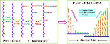
To illustrate the initiation and propagation processes more clearly, the grafting polymerization was conducted in 1 h and samples were taken at an interval of 10 min. The percentage of CTFE initiated and MMA grafted in all the copolymers as a function of the reaction time are shown in Fig. 3. As the reaction time is increased, the amount of CTFE initiated increased slowly and linearly, which means the molar concentration of active species RMn–Cl (n = 1, 2, 3…) formed increased linearly against reaction time with a very small slope (about 0.13% per min). The percentage of grafted MMA increased linearly as well as reaction time increased. In an ideal living (or controlled) radical polymerization system, all the active sites are supposed to be initiated immediately and the amount of active sites should be constant during the propagation process since the chain termination reaction is negligible. As a result, all the active sites have the same possibility to react and the reaction rate to insert monomers during the propagation process is characterized with a very small molecular weight distribution of resultant polymer and a linearly increased monomer conversion against reaction time. Apparently, the grafted copolymer synthesized in the present study is far from the ideal case. First of all, R–Cl was converted to RM–Cl slowly as the reaction time was increased. However, the following propagation of RM–Cl is much faster compared to the initiation of R–Cl. As a result, the polymer chain formed from RM–Cl increased in length quickly until the next R–Cl is activated and converted into RM–Cl. As more RM–Cl and RMn–Cl formed, the increasing speed of polymer chain length was reduced since the MMA conversion was increasing in a linear fashion, which means earlier the grafting polymer chain formed resulted in longer chain lengths being observed. Moreover, a large quantity of CTFE units is not initiated since the initiation reaction was rather slow. Therefore, the structure of the grafted copolymer could be illustrated as a grafted copolymer, containing a small quantity of side chains and the chain length is varied in a large scale as shown in Scheme 3.
 |
| Fig. 3 MMA grafted (%) and CTFE activated (%) in the P(VDF-CTFE)-g-PMMA calculated from eqn (2) and (5) catalyzed with FeCl2/PPh3/VC. | |
 |
| Scheme 3 Structural evolution of grafted copolymers synthesized from ATRP process (A, ideal case; B, real case). | |
3.4 Effect of catalyst system on the structure of P(VDF-CTFE)-g-PMMA
From the abovementioned discussion, it is not difficult to find out that the formation of the structure is mainly due to the reactivity difference of initial initiator (R–Cl) and the propagation species (RMn–Cl) with FeCl2/PPh3 catalyst. Besides the chemical bonding difference of R–Cl and RMn–Cl, the catalyst system should influence the reactivity as well, which has been reported in ATRP system.26 Therefore, it is logical to believe that the different catalyst system should affect the structure of the grafted copolymer as well. For comparison purposes, CuCl/BPy was used as a catalyst for the synthesis of P(VDF-CTFE)-g-PMMA under the chosen reaction conditions. Samples were taken at a time interval of 10 min, and all the copolymers were extracted to remove homopolymers followed by hydrogenation with n-Bu3SnH/AIBN as well for the structural characterization. The MMA grafted (%) and the percentage of CTFE units activated in all the samples were calculated using eqn (2) and (5) and the results are summarized in Table 1. As the reaction time was increased, both the molar percentage of CTFE activated and MMA grafted onto P(VDF-CTFE) catalyzed with CuCl/BPy increased and exhibited similar trend as that of FeCl2/PPh3/VC. However, much higher CTFE content and MMA monomer have been consumed in the CuCl/BPy system, which could be attributed to the much higher activity of CuCl/BPy catalyst than that of FeCl2/PPh3/VC. This also suggests that the grafted copolymers should possess rather different structures based on the activated CTFE content and MMA grafted onto P(VDF-CTFE).
Table 1 MMA grafted (%) and CTFE initiated (%) in P(VDF-CTFE)-g-PMMA catalyzed with two types of catalyst determined by 1H NMR
Polymer structure |
Reaction time (min) ti (i = 1, 2, …, 6) |
t1 = 10 min |
t2 = 20 min |
t3 = 30 min |
t4 = 40 min |
t5 = 50 min |
t6 = 60 min |
Experimental conditions: [R–Cl]/[FeCl2]/[PPh3]/[VC]/[MMA] = 1 : 1 : 2 : 1 : 80 in molar, T = 100 °C, 5 g P(VDF-CTFE) as initiator and 150 mL DMSO as solvent. Experimental conditions: [R–Cl]/[CuCl]/[BPy]/[MMA] = 1 : 1 : 2 : 80, in molar, T = 100 °C, 5 g P(VDF-CTFE) as initiator and 150 mL DMSO as solvent. The molar percentage of CTFE initiated is calculated from eqn (5). |
FeCl2/PPh3/VC catalysta |
MMA grafted (%) |
0.33 |
0.67 |
1.03 |
1.40 |
1.79 |
2.05 |
CTFE initiatedc (%) |
1.25 |
2.58 |
3.83 |
5.08 |
6.44 |
7.80 |
CuCl/BPy catalystb |
MMA grafted (%) |
0.93 |
4.40 |
10.26 |
17.09 |
22.43 |
25.56 |
CTFE initiatedc (%) |
13.73 |
23.92 |
31.56 |
37.61 |
41.68 |
43.63 |
To obtain more detailed structure information of the grafted copolymers and illustrate how the grafted copolymers were formed and propagated, the molar content of the active sites (RM–Cl) formed at different time intervals was calculated from eqn (8),
|
ni = [(CTFE initiated%)ti − (CTFE initiated%)ti−1] × [CTFE]0 mmol
| (8) |
where
ti (
i = 1, 2, …, 6) refer to the different reaction times.
t1 means the polymerization in first 10 min,
t2 represents the polymerization in 20 min, and so on. As shown in
Table 2, a consistent molar content of CTFE (0.008 to 0.009 mmol min
−1) was initiated and formed RM–Cl in every time intervals in FeCl
2/PPh
3/VC system, which means the concentration of overall RM
n–Cl (
n = 1, 2, 3…) species increased linearly with reaction time, as shown in
Fig. 4. In a different case, the CTFE molar content activated by CuCl/BPy at different time intervals decreased rapidly from 0.072 mmol min
−1 to 0.01 mmol min
−1 as the reaction time was increased, which means that many CTFE units are quickly initiated and converted into RM–Cl followed by a chain propagation process. The initiation speed of CTFE is quickly reduced and the overall concentration of RM
n–Cl (
n = 1, 2, 3…) species was improved but possessed a deviating linear relationship against reaction time, as shown in
Fig. 4.
Table 2
, ni (mmol), molar percentage (xni), weight percentage (wni) and molecular weight Mni (g mol−1) of grafted PMMA onto P(VDF-CTFE) at different time intervals determined by 1H NMR
Time intervala (min) |
i = 1 (0–10) |
i = 2 (10–20) |
i = 3 (20–30) |
i = 4 (30–40) |
i = 5 (40–50) |
i = 6 (50–60) |
The time interval between two adjacent time points. For example: (10–20) is referring to the second interval of the reaction namely the polymerization conducted between the 10th and 20th minute since the reaction started. The molar content of CTFE initiated in different intervals is calculated from eqn (8). The average polymerization degree of grafted PMMA on all initiated CTFEs is calculated from eqn (9). The average molecular weight of PMMA side chains formed at different time intervals is obtained from eqn (10). The molar percentage of side chains formed in different time intervals are calculated from eqn (11). The weight percentage of side chains formed in different time intervals are calculated from eqn (11). |
FeCl2/PPh3/VC catalyst |
nib (mmol) |
0.082 |
0.087 |
0.082 |
0.082 |
0.089 |
0.089 |
c |
21.0 |
10.5 |
7.6 |
5.8 |
4.8 |
2.7 |
Mnid |
5250 |
3140 |
2090 |
1330 |
750 |
270 |
xnie (%) |
16.03 |
17.05 |
16.05 |
16.05 |
17.42 |
17.42 |
wnif (%) |
39.63 |
25.47 |
15.96 |
10.16 |
6.21 |
2.24 |
CuCl/BPy catalyst |
ni (mmol) |
0.719 |
0.534 |
0.401 |
0.317 |
0.213 |
0.102 |
 |
5.4 |
11.6 |
14.9 |
14.5 |
10.3 |
5.7 |
Mni |
6240 |
5700 |
4540 |
3050 |
1600 |
570 |
xni (%) |
31.45 |
23.36 |
17.54 |
13.87 |
9.32 |
4.46 |
wni (%) |
41.87 |
28.40 |
16.99 |
9.02 |
3.18 |
0.54 |
 |
| Fig. 4 Molar concentration of the initiated CTFE versus reaction time during ATRP process catalyzed with FeCl2/PPh3/VC and CuCl/BPy. | |
The grafting propagation process was characterized with the average polymerization degree (
) of PMMA grafted on P(VDF-CTFE) in different time intervals.
could be calculated by dividing the molar content of grafted MMA in the time interval of i with molar content of overall RMn–Cl (n = 1, 2, 3…) formed in time t from the following eqn (9),
|
 | (9) |
where MMA grafted (%) and CTFE initiated (%) at different time intervals are from
Table 1. The

of the MMA grafted with FeCl
2/PPh
3/VC catalyst dropped quickly as reaction time increases, as shown in
Table 2, which means that the average growth speed of each grafting chain decreases as a function of reaction time. Unlike FeCl
2/PPh
3/VC catalyst, the

of the MMA grafted with CuCl/BPy catalyst increased at first and then was maintained at a constant for a while before starting to drop. This may be attributed to the enhanced concentration of RM
n–Cl (
n = 1, 2, 3…) of the species and the decreased MMA concentration. The results strongly indicate that the reaction reactivity of CuCl/BPy catalyst is higher than that of FeCl
2/PPh
3/VC.
In addition, the average molecular weight of every PMMA side chain formed at different time intervals (Mni, i = 1, 2, …, 6) could be obtained by accumulating all the amount of the grafted MMA units during the polymerization process since CTFEs were initiated (as suggested in eqn (10)),
|
 | (10) |
where
M0 is the molecular weight of monomer. The data in
Table 2 shows that the molecular weight of the grafting polymer chains formed at different time intervals catalyzed with both catalysts shows a similar decreasing trend as reaction time increases, which means that the earlier the grafted chains are generated, the longer grafted chain length would be obtained as suggested in
Scheme 3. The difference is the molecular weight of the side chains obtained from FeCl
2/PPh
3/VC system is reduced more quickly than CuCl/BPy. This means that the length difference of side chains obtained from FeCl
2/PPh
3/VC system is more significant than that of CuCl/BPy.
Moreover, the molar (xi) and weight (wi) percentage of side chains formed at different time intervals with molecular weight of Mni could be obtained from the following equations,
|
 | (11) |
|
wi = Mni × ni/(MMA grafted (%))t6 × [MMA]0 × M0 (i = 1, 2, …, 6)
| (12) |
The molar percentage of different molecular weight side chains has a similar value when FeCl2/PPh3/VC is used as catalyst, as listed in Table 2. The molar percentage distribution of PMMA side chains was relatively concentrated when CuCl/BPy is used as catalyst.
To illustrate the side chain length difference of copolymers obtained from two catalysts more clearly, the number-average molecular weight (
n) and weight-average molecular weight (
w) of the PMMA grafted in 1 h as well as the PDI are estimated from the following equations (eqn (13)–(15)) according to the results listed in Table 3.
|
 | (13) |
|
 | (14) |
|
 | (15) |
Table 3
n,
w and PDI of the PMMA side chains catalyzed with different catalysts
Catalyst |
FeCl2/PPh3/VC |
CuCl/BPy |
n (g mol−1) |
2104 |
4693 |
w (g mol−1) |
3491 |
5338 |
PDI |
1.62 |
1.14 |
As shown in Table 3, the average molecular weight of PMMA grafted onto P(VDF-CTFE) catalyzed with CuCl/BPy was larger than that of FeCl2/PPh3/VC, which confirms their catalytic activity difference as discussed above. Moreover, the smaller PDI obtained from CuCl/BPy may address the better controllability of the CuCl/BPy catalyst than the FeCl2/PPh3/VC catalyst as well.
Taking the grafting density into account, the P(VDF-CTFE)-g-PMMA synthesized from two catalysts could are illustrated schematically in Fig. 5. A small amount of PMMA side chains with large length distribution were grafted onto P(VDF-CTFE) when FeCl2/PPh3/VC was utilized as the catalyst. On the contrary, a great number of PMMA side-chains with more uniform chain length are formed when the polymerization is catalyzed with CuCl/BPy under the same reaction conditions (Fig. 5A). In addition, the molecular weight distribution was more concentrated when obtained using CuCl/BPy catalyst (as shown in Table 2 and Fig. 5C), while much more scattered grafted polymer chains were obtained in the copolymer catalyzed with FeCl2/PPh3/VC (Table 2 and Fig. 5B). This further confirms the better controllability and higher activity of the CuCl/BPy catalyst system.
 |
| Fig. 5 (A) Schematic illustration of the different structure of P(VDF-CTFE)-g-PMMA catalyzed with different catalysts; (B) the percentage of different molecular weight with FeCl2/PPh3/VC; (C) the percentage of different molecular weight with CuCl/BPy. | |
3.5 Kinetic analysis of the initiation and propagation rate during the synthesis of P(VDF-CTFE)-g-PMMA
To understand the evolution of the polymerization deeply and correlate the structure of the copolymer to the fundamental parameters, a kinetic analysis was conducted and fitted with the experimental results. The grafting polymerization of MMA initiated with P(VDF-CTFE) was divided into two steps, including the initiation reaction and the propagation reaction since the reaction system possesses two types of active species (R–Cl and RMn–Cl (n = 1, 2, 3…)) and their reaction kinetics constants with catalysts should be different. As shown in Scheme 4, the initiation reaction is involving the formation of initial radical R* from redox reaction between catalysts (MtCln/L) and CTFE on P(VDF-CTFE) (marked as R–Cl) followed by the insertion of first monomer (M) onto R* to generate RM* and quickly chain transferred to MtCln+1/L to form RM–Cl. The equilibrium constant of ATRP at this stage is marked as KATRP1, which refers to the ratio of kact1 divided by kdeact1. Ri and ki represent how fast the formation of RM–Cl, are the initiation rate and the initiation rate constant. The propagation reaction starts from the activation of RMn–Cl (n = 1, 2, 3…) to form RM*n followed by the insertion of monomers as well as the chain transfer reaction to MtCln+1/L to generate RMn+1Cl. The equilibrium constant of ATRP at this stage is assumed to be the same for similar structure RMn–Cl with different n and is marked as KATRP2, which refers to the ratio of kact2 divided by kdeact2. Rp and kp refer to how fast the polymer chains are growing, are the propagation rate and its rate constant.
 |
| Scheme 4 The initiation and propagation reactions, involving two types of initiator species R–Cl and RMn–Cl. (Mt–Cln/L stands for FeCl2/PPh3 or CuCl/BPy). | |
From the above discussion, it is known that the initiation reaction takes place in two steps, including the generation of R* from the reduction reaction of R–Cl and the addition reaction of R* toward monomers. Therefore, the initiation rate Ri should be dominated by the slower process. Usually, the first step in ATRP is rather fast and the equilibrium is established in a short time. The second step is the rate controlling step and Ri could be expressed as Ri = ki[R*][M] (red in Scheme 4). However, the activating reaction of R–Cl onto P(VDF-CTFE) in this case is rather slow as discussed above and the first step is much slower than the addition reaction of R* to a monomer. Therefore, Ri should be dominated by the first step instead of the second one and it should be defined as eqn (16),
|
 | (16) |
From Scheme 4, the propagation rate Rp could be expressed as eqn (17),
|
 | (17) |
Integrating eqn (16) against reaction time from 0 to t,
, then
and
|
[R–Cl]t = [R–Cl]0 e−k1t
| (18) |
is obtained, where
K1 is equal to
kact1[MtCl
n/L]. Therefore, the initiation rate is directly correlated to the activation rate constant
kact1 and the concentration of metal salts in reductive states. The value of
K1 could be obtained by fitting the function [R–Cl]
t = [R–Cl]
0![[thin space (1/6-em)]](https://www.rsc.org/images/entities/char_2009.gif)
e
−k1t with the experimental results ([CTFE]
t ∼ t). As shown in
Fig. 6,
K1 of FeCl
2/PPh
3/VC and CuCl/BPy systems were determined to be 1/750 and 1/77, respectively, which means the initiation activity of FeCl
2/PPh
3/VC system towards P(VDF-CTFE) is much smaller than that of the CuCl/BPy system under the same conditions. Because the initial concentration of metal complex ([MtCl
n/L]) is consistent, the dramatic difference of
K1 observed in the two catalysts should be mainly induced by the different
kact1, namely, the reductive capabilities of the metal complex toward C–Cl onto P(VDF-CTFE). Moreover, the initiation speed of CTFE in both cases was not sufficiently high, which leaves a large quantity of CTFE units un-initiated in the resulting copolymers. Ideally, the CTFE content should be reduced to nearly zero in the very short period at the beginning of the polymerization, which means that
K1 should be sufficiently high as indicated in the curve of the ideal case in
Fig. 6, with
K1 = 0.3 is taken as an instance.
 |
| Fig. 6 Experimental and theoretical results of [CTFE]t or [R–Cl]t versus reaction time catalyzed with different catalysts. | |
In the propagation step, [RMn–Cl] in the ideal living/controlled radical polymerization system is usually treated as a constant ([R–Cl]0) since the structure of [R–Cl] is similar to [RMn–Cl] and their activation energies are regarded as being the same. Therefore, a linear increasing trend of ln([M]0/[M]t) against reaction time t would be obtained and recognized as one of the most popular utilized relationships to characterize the controlled or living nature of ATRP or other living radical polymerizations since it is following the first-order kinetics. However, the concentration of propagation active sites should not be treated as a constant any longer since R–Cl and RMn–Cl (n = 1, 2, 3…) are treated as different species in the present study. Namely, the concentration of propagation active species [RMn–Cl] = [R–Cl]0 − [R–Cl]t is not a constant but a function of reaction time t and is obtained as [R–Cl]t = [R–Cl]0
e−k1t based on the above discussion. Therefore, by integrating reaction time from 0 to t of eqn (17), [M] as a function of time t could be observed as
|
 | (19) |
where
K2 is equal to
kpKATRP2[MtCl
n/L]/[MtCl
n+1/L]. By fitting the experimental results (ln([M]
0/[M]
t)
vs. t) with
eqn (19) as shown in
Fig. 7,
K2 of CuCl/BPy and FeCl
2/PPh
3/VC system were determined to be 0.3 and 0.2, respectively. As indicated in
K2 =
kpKATRP2[MtCl
n/L]/[MtCl
n+1/L], the difference of
K2 between two catalyst systems is from the term of
KATRP2[MtCl
n/L]/[MtCl
n+1/L] since the addition reaction rate constant (
kp) of RM
*n with MMA monomer should be the same. Apparently, the slightly bigger
K2 of CuCl/BPy system may be attributed to its higher redox potential than that of FeCl
2/PPh
3/VC system. The smaller
K1 and
K2 of FeCl
2/PPh
3/VC system are responsible for the lower MMA conversion and average molecular weight of PMMA grafted than CuCl/BPy catalyst.
 |
| Fig. 7 Kinetic plot of ln([M]0/[M]t) for ATRP of MMA grafted onto P(VDF-CTFE) catalyzed with different catalysts. | |
Although the polymerization has been divided into two steps, which is depicted in Scheme 4, both the catalyst and monomer are at the same concentration during the polymerization process. At the beginning, the concentration of RMn–Cl (n = 1, 2, 3…) is zero and only the initiation reaction would take place. Once the RMn–Cl species are formed, the propagation reaction starts and the catalysts (MtCln/L) are involved in two possible reaction routes, including reducing either the R–Cl or RMn–Cl species. Apparently, which one is more favorable is governed by the reductive capability of metal complex towards the R–Cl and RMn–Cl species, which should be dominated by K1 and K2. In the FeCl2/PPh3/VC system, K1 and K2 are 1/750 and 0.2, respectively, which means the propagation rate is over 150 times of the initiation rate when [R–Cl] and [RMn–Cl] are the same. Moreover, the propagation reaction shows very high priority over the initiation reaction under the chosen reaction conditions. In CuCl/BPy case, K1 and K2 are 1/77 and 0.3 and the propagation rate is about 23.1 times of the initiation rate under the chosen conditions. The propagation reaction still shows a very high priority although it is much lower than that in FeCl2/PPh3/VC system.
In an ideal LRP system, the initiator R–Cl possessing the similar structure with growing polymer chain RMn–Cl is usually applied in synthesizing polymer with narrow polymer distribution since K1 is approximately equal to K2, which means that all the active species could be treated equally and activated by catalyst with the same probability. Alternatively, highly active initiators49 with a much bigger K1 value than K2 could be utilized as well. The initiation stage takes a very short time to convert all the R–Cl species into RM–Cl before the propagation of all the polymer chains starts with the exactly same rate. In both cases, the polymerization with good control/living character and resultant polymers with a small PDI could be expected. However, if initiators with low activity such as P(VDF-CTFE) have to be utilized in ATRP, K1 would be much smaller than K2 and the high priority of the propagation reaction would lead to a very poor controlling character of the polymerization together with the wide molecular weight distribution of the resultant copolymer. Apparently, the relationship of K1 and K2, especially the value of K1 plays the dominant role. The smaller values of K1, the poorer controlling character of polymerization together with the high PDI of the polymer are expected to be observed. The grafted copolymer structure is more like a block copolymer with several very long grafted copolymer chains and some very short chains together with unreacted R–Cl structure present as a majority species, as suggested in Scheme 3. In general, to obtain well controlled/living polymerization character in an ATRP process, a high initiation rate constant K1 has to be ensured by increasing either the addition reaction rate constant of R* with monomers or the reductive performance of the metal complex catalysts if the initiator structure is reserved.
4 Conclusions
In conclusion, PMMA with different chain lengths and PDI were grafted onto P(VDF-CTFE) catalyzed with FeCl2/PPh3 and CuCl/BPy complexes via an ATRP process. By removing homo-PMMA from the resultant copolymer and converting the un-initiated CTFE into TrFE units, the detailed structural information, including the grafting density, average chain length, average molecular weight and its distribution of P(VDF-CTFE)-g-PMMA were obtained for the two catalysts. The grafted copolymer synthesized from CuCl/BPy catalyst possessed higher grafting density, larger average molecular weight and smaller PDI than that of the FeCl2/PPh3 system for its higher reductive potential. The evolution of the PMMA side chains was clearly illustrated by analyzing the structure of P(VDF-CTFE)-g-PMMA synthesized from two catalysts with different reaction times. By dividing the propagation reaction into two different steps for the difference of initial (R–Cl) and growing (RMn–Cl) active species, the kinetics analysis was conducted and found to fit the experimental results very well. Two kinetics constants (K1 and K2) were obtained that dominate the initiation and propagation performance of ATRP process. The K1 of CuCl/BPy is about ten times larger than that of FeCl2/PPh3/VC for its relatively high reduction potential to the R–Cl species as well as the molar concentration ratio between the reductive and oxidized species. The value of K2 obtained from the two catalysts is 0.2 and 0.3, which suggests the propagation performance of the two catalysts was rather close. The big difference of K1 between the two catalysts is responsible for the structural variety of the copolymer obtained as well as the varied polymerization performance. The poor uniformity of the side chains mostly originates from the much lower active capability of catalysts to R–Cl than that of RMn–Cl species, namely smaller K1 than K2. The results may help to understand not only the detailed polymer structure synthesized from the ATRP process more precisely but also the evolution of the growing polymer chains under different reaction conditions more directly.
Acknowledgements
This study was financially supported by the National Nature Science Foundation of China-NSFC (no. 10976022, 51103115, 50903065), the Fundamental Research Funds for the Central Universities (xjj2013075), the National Basic Research Program of China (no. 2009CB623306), the International Science & Technology Cooperation Program of China (2013DFR50470), the Natural Science Basic Research Plan in the Shaanxi Province of China (no. 2013JZ003).
References
- V. M. C. Coessens and K. Matyjaszewski, J. Chem. Educ., 2010, 87, 916–919 CrossRef CAS.
- W. A. Braunecker and K. Matyjaszewski, Prog. Polym. Sci., 2007, 32, 93–146 CrossRef CAS PubMed.
- L. Bai, L. Zhang, Y. Liu, X. Pan, Z. Cheng and X. Zhu, Polym. Chem., 2013, 4, 3069–3076 RSC.
- J. S. Wang and K. Matyjaszewski, J. Am. Chem. Soc., 1995, 117, 5614–5615 CrossRef CAS.
- M. Kato, M. Kamigaito, M. Sawamoto and T. Higashimura, Macromolecules, 1995, 28, 1721–1723 CrossRef CAS.
- M. Kamigaito, T. Ando and M. Sawamoto, Chem. Rev., 2001, 101, 3689–3745 CrossRef CAS PubMed.
- M. Ouchi, T. Terashima and M. Sawamoto, Chem. Rev., 2009, 109, 4963–5050 CrossRef CAS PubMed.
- V. M. C. Coessens, T. Pintauer and K. Matyjaszewski, Prog. Polym. Sci., 2001, 26, 337–377 CrossRef CAS.
- K. Davis and K. Matyjaszewski, Adv. Polym. Sci., 2002, 159, 1–13 CrossRef.
- K. Matyjaszewski, Prog. Polym. Sci., 2005, 30, 858–875 CrossRef CAS PubMed.
- N. V. Tsarevsky and K. Matyjaszewski, Chem. Rev., 2007, 107, 2270–2299 CrossRef CAS PubMed.
- F. J. Xu, K. G. Neoh and E. T. Kang, Prog. Polym. Sci., 2009, 34, 719–761 CrossRef CAS PubMed.
- Y. Ogura, T. Terashima and M. Sawamoto, ACS Macro Lett., 2013, 2, 985–989 CrossRef CAS.
- S.-H. Lee, M. Ouchi and M. Sawamoto, Macromolecules, 2012, 45, 3702–3710 CrossRef CAS.
- K. Nakatani, Y. Ogura, Y. Koda, T. Terashima and M. Sawamoto, J. Am. Chem. Soc., 2012, 134, 4373–4383 CrossRef CAS PubMed.
- T. Terashima, A. Nomura, M. Ito, M. Ouchi and M. Sawamoto, Angew. Chem., Int. Ed., 2011, 50, 7892–7895 CrossRef CAS PubMed.
- W. Jakubowski and K. Matyjaszewski, Macromolecules, 2005, 38, 4139–4146 CrossRef CAS.
- S. Qin, J. Saget, J. Pyun, S. Jia, T. Kowalewski and K. Matyjaszewski, Macromolecules, 2003, 36, 8969–8977 CrossRef CAS.
- D. Neugebauer, M. Theis, T. Pakula, G. Wegner and K. Matyjaszewski, Macromolecules, 2006, 39, 584–593 CrossRef CAS.
- B. Dufour, C. Tang, K. Koynov, Y. Zhang, T. Pakula and K. Matyjaszewski, Macromolecules, 2008, 41, 2451–2458 CrossRef CAS.
- M. Li, N. M. Jahed, K. Min and K. Matyjaszewski, Macromolecules, 2004, 37, 2434–2441 CrossRef CAS.
- Y. Miura, K. Satoh, M. Kamigaito, Y. Okamoto, T. Kaneko, H. Jinnai and S. Kobukata, Macromolecules, 2007, 40, 465–473 CrossRef CAS.
- H.-I. Lee, K. Matyjaszewski, S. Yu and S. S. Sheiko, Macromolecules, 2005, 38, 8264–8271 CrossRef CAS.
- V. Percec, B. Barboiu, C. Grigoras and T. K. Bera, J. Am. Chem. Soc., 2003, 125, 6503–6516 CrossRef CAS PubMed.
- K. T. Powell, C. Cheng and K. L. Wooley, Macromolecules, 2007, 40, 4509–4515 CrossRef CAS PubMed.
- W. Tang, Y. Kwak, W. Braunecker, N. V. Tsarevsky, M. L. Coote and K. Matyjaszewski, J. Am. Chem. Soc., 2008, 130, 10702–10731 CrossRef CAS PubMed.
- Y. Zhang, Y. Wang and K. Matyjaszewski, Macromolecules, 2011, 44, 683–685 CrossRef CAS.
- B. Ameduri, B. Boutevin and G. Kostov, Prog. Polym. Sci., 2001, 26, 105–187 CrossRef CAS.
- B. Ameduri, Macromolecules, 2010, 43, 10163–10184 CrossRef CAS.
- K. Johns and G. Stead, J. Fluorine Chem., 2000, 104, 5–18 CrossRef CAS.
- L. Q. Xu, J. C. Chen, R. Wang, K.-G. Neoh, E.-T. Kang and G. D. Fu, RSC Adv., 2013, 3, 25204–25214 RSC.
- R. Chan and V. Chen, J. Membr. Sci., 2004, 242, 169–188 CrossRef CAS PubMed.
- L. Yan, Y. S. Li and C. B. Xiang, Polymer, 2005, 46, 7701–7706 CrossRef CAS PubMed.
- Y. H. Zhao, Y. L. Qian, B. K. Zhu and Y. Y. Xu, J. Membr. Sci., 2008, 310, 567–576 CrossRef CAS PubMed.
- M. F. Zhang and T. P. Russell, Macromolecules, 2006, 39, 3531–3539 CrossRef CAS.
- F. He, B. W. Luo, S. J. Yuan, B. Liang, C. Choong and S. O. Pehkonenc, RSC Adv., 2014, 4, 105–117 RSC.
- S. Samanta, D. P. Chatterjee, S. Manna, A. Mandal, A. Garai and A. K. Nandi, Macromolecules, 2009, 42, 3112–3120 CrossRef CAS.
- F. X. Guan, Z. Z. Yuan, E. W. Shu and L. Zhu, Appl. Phys. Lett., 2009, 94, 052907 CrossRef PubMed.
- F. X. Guan, L. Y. Yang, J. Wang, B. Guan, K. Han, Q. Wang and L. Zhu, Adv. Funct. Mater., 2011, 21, 3176–3188 CrossRef CAS.
- F. X. Guan, J. Wang, L. Y. Yang, J.-K. Tseng, K. Han, Q. Wang and L. Zhu, Macromolecules, 2011, 44, 2190–2199 CrossRef CAS.
- L. Y. Yang, E. Allahyarov, F. X. Guan and L. Zhu, Macromolecules, 2013, 46, 9698–9711 CrossRef CAS.
- E. M. W. Tsang, Z. B. Zhang, Z. Q. Shi, T. Soboleva and S. Holdcrof, J. Am. Chem. Soc., 2007, 129, 15106–15107 CrossRef CAS PubMed.
- Z. C. Zhang, E. Chalkova, M. Fedkin, C. M. Wang, S. N. Lvov, S. Komarneni and T. C. M. Chung, Macromolecules, 2008, 41, 9130–9139 CrossRef CAS.
- J. J. Li, S. B. Tan, S. J. Ding, H. Y. Li, L. J. Yang and Z. C. Zhang, J. Mater. Chem., 2012, 22, 23468–23476 RSC.
- J. J. Li, X. Hu, G. X. Gao, S. J. Ding, H. Y. Li, L. J. Yang and Z. C. Zhang, J. Mater. Chem. C, 2013, 1, 1111–1121 RSC.
- Y. Y. Lu, J. Claude, Q. M. Zhang and Q. Wang, Macromolecules, 2006, 39, 6962–6968 CrossRef CAS.
- Y. Y. Lu, J. Claude, B. Neese, Q. M. Zhang and Q. Wang, J. Am. Chem. Soc., 2006, 128, 8120–8121 CrossRef CAS PubMed.
- Z. M. Wang, Z. C. Zhang and T. C. M. Chung, Macromolecules, 2006, 39, 4268–4271 CrossRef CAS.
- X. Y. Zhang, C. K. Fu, L. Feng, Y. Ji, L. Tao, Q. Huang, S. X. Li and Y. Wei, Polymer, 2012, 53, 3178–3184 CrossRef CAS PubMed.
Footnote |
† Electronic supplementary information (ESI) available. See DOI: 10.1039/c4ra15190a |
|
This journal is © The Royal Society of Chemistry 2015 |
Click here to see how this site uses Cookies. View our privacy policy here.