
Sulfur-doped porous carbon nanosheets as an advanced electrode material for supercapacitors†
Wenfang Deng,
Yijia Zhang,
Lu Yang,
Yueming Tan*,
Ming Ma and
Qingji Xie
Key Laboratory of Chemical Biology and Traditional Chinese Medicine Research, Ministry of Education of China, College of Chemistry and Chemical Engineering, Hunan Normal University, Changsha 410081, China. E-mail: tanyueming0813@126.com
First published on 20th January 2015
Abstract
Direct carbonization and simultaneous chemical activation of a cobalt ion-impregnated sulfonic acid ion exchange resin is found to be an efficient approach to the large-scale synthesis of sulfur-doped porous carbon nanosheets (S-PCNS) for supercapacitors with high specific energy and excellent rate capability. The as-prepared S-PCNS showed a three-dimensional interconnected structure, high graphitization degree, high C/O atomic ratio (22.9![[thin space (1/6-em)]](https://www.rsc.org/images/entities/char_2009.gif) :1), high-level sulfur doping (9.6 wt%), high specific surface area (2005 m2 g−1), and good porosity. The S-PCNS serving as an electrode material for supercapacitors exhibited a specific capacitance as high as 312 F g−1 at 0.5 A g−1, excellent rate capability (78% of capacitance retention at 50 A g−1), high energy density (11.0 W h kg−1 at 0.5 A g−1), and outstanding cycling stability (∼97% of its initial capacitance after 10000 cycles at 2 A g−1) in 6.0 M aqueous KOH electrolyte. Due to the unique structure of S-PCNS, the specific capacitance of S-PCNS is higher than that of sulfur-doped activated carbon. The excellent capacitance performance coupled with the facile synthesis of S-PCNS indicates a potential electrode material for supercapacitors.
:1), high-level sulfur doping (9.6 wt%), high specific surface area (2005 m2 g−1), and good porosity. The S-PCNS serving as an electrode material for supercapacitors exhibited a specific capacitance as high as 312 F g−1 at 0.5 A g−1, excellent rate capability (78% of capacitance retention at 50 A g−1), high energy density (11.0 W h kg−1 at 0.5 A g−1), and outstanding cycling stability (∼97% of its initial capacitance after 10000 cycles at 2 A g−1) in 6.0 M aqueous KOH electrolyte. Due to the unique structure of S-PCNS, the specific capacitance of S-PCNS is higher than that of sulfur-doped activated carbon. The excellent capacitance performance coupled with the facile synthesis of S-PCNS indicates a potential electrode material for supercapacitors.
Introduction
Supercapacitors can combine the advantages of conventional dielectric capacitors and rechargeable batteries, exhibiting many advantages including high rate capability, pulse power supply, long cycle life, superior reversibility, simple principle, facile dynamics of charge propagation, and low maintenance costs.1–4 Supercapacitors have attracted great interest for a wide and growing range of applications including consumer electronics, energy management, memory back-up systems, industrial power, and mobile electrical systems.5–8 The charge storage of supercapacitors is based on the interfacial double layer of electrode material,9–11 or based on Faradic reactions occurring at the electrode interface, such as transition-metal oxides/hydroxides and conducting polymers.12–18 Electrochemical double-layer capacitors using various carbons with high surface areas as electrode materials are the most commonly used supercapacitors.19–26 An ideal carbon material for supercapacitors should have large surface area, high electric conductivity, and suitable pore size distribution. Synthesis of novel carbons for high-performance supercapacitor applications is of great interest and importance.Chemical doping carbon materials with heteroatoms (N, S, P or B) is an effective method to tailor electronic properties and manipulate the surface chemistry, which can provide an alternative strategy for impressively enhancing capacitance performance of carbon materials.27–39 In particular, the sulfur-doped carbons have been emerged as candidates for supercapacitors in the past few years.27,34–39 The enhanced performance of sulfur-doped carbons is linked to the electron-rich aromatic sulfide, which provides a more polarized surface under an applied electric field, resulting in an increased electrolyte dielectric constant and a facilitated charge transfer process.34 In addition, a series of redox Faradic reactions take place on the sulfur-doped carbons due to the presence of sulfone and sulfoxide species, which leads to increased pseudocapacitance.27,34
Herein, sulfur-doped porous carbon nanosheets (S-PCNS) were facilely synthesized by direct carbonization and simultaneous chemical activation of a cobalt ion-impregnated sulfonic acid ion exchange resin. Due to the combined advantages of three-dimensional interconnected structure, high graphitization degree, high content of sulfur doping, high specific surface area, and good mesoporosity, the S-PCNS exhibited high specific capacitance, excellent rate capability, high energy density, and outstanding cycling stability, indicating a potential electrode material for supercapacitors.
Experimental section
Instrumentation and chemicals
Electrochemical experiments were conducted on a CHI760E electrochemical workstation (CH Instrument Co., U. S. A.). Scanning electron microscopy (SEM) and transmission electron microscopy (TEM) studies were conducted on a Hitachi S4800 scanning electron microscope and a TECNAI F-30 high-resolution transmission electron microscope, respectively. Atomic force microscopy (AFM) measurements were carried out with a PicoLE scanning probe microscope (Molecular Imaging, Arizona, USA). X-Ray diffraction (XRD) and X-ray photoelectron spectroscopy (XPS) studies were performed on a PANalytical X'pert Pro X-ray diffractometer and a PHI QUANTUM 2000 X-ray photoelectron spectroscopic instrument, respectively. Surface area and pore size were determined by a surface area and porosity analyzer (Micromeritics Instrument Corp. ASAP2020). All chemicals were of analytical grade and used without further purification. Ultrapure water (Millipore, ≥18 MΩ cm) was used throughout.Material synthesis
For the synthesis of S-PCNS, the pretreated sulfonic acid ion exchange resin was impregnated with Co2+ in cobalt nitrate solution with concentration of 0.05 M for 12 h. The ion exchange resin was washed with deionized water and dried at 60 °C in a vacuum drying oven. Then the Co2+-impregnated ion exchanged resin was activated by heating at 800 °C with KOH for 2 h in N2 atmosphere, with a heating ratio of 2 °C min−1. The KOH/resin ratio is 4:1. Finally, the resulting sample was etched in excessive 0.1 M HCl aqueous solution. The resulting products were collected by centrifugation, washed with deionized water and finally dried at 60 °C in a vacuum drying oven for 12 h. Sulfur-doped activated carbon (S-AC) was synthesized similarly as the S-PCNS except that the sulfonic acid ion exchange resin was not impregnated with Co2+.
Electrochemical studies
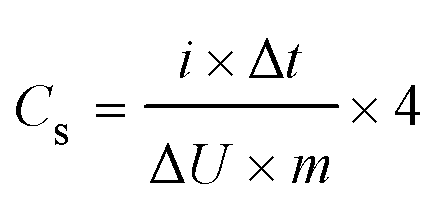
The electrode was fabricated by pressing a mixture of 90 wt% active material, 5 wt% acetylene black, and 5 wt% polytetrafluoroethylene onto a piece of nickel foil (1.5 cm2) under 15 MPa. Supercapacitors were assembled in a symmetrical two electrode configuration with a membrane sandwiched between two electrodes. The mass loading of active material in each electrode was 3 mg. 6 M aqueous KOH was used as electrolytic solution. Cyclic voltammetry studies were carried out between 0 and 1 V at scan rates from 10 to 1000 mV s−1. Galvanostatic charge–discharge measurements were carried out at current densities from 0.5 to 50 A g−1 between 0 and 1 V. Electrochemical impedance spectroscopy (EIS) measurements were carried out in the frequency range from 10 kHz to 10 mHz, with a voltage amplitude of 5 mV. The specific capacitance (Cs, F g−1) of active material is calculated from the discharge curves according to the following equation:where i (A) and Δt (s) are the discharge current and the discharge time, respectively, ΔU (V) is the voltage change excluding the iR drop within the discharge time, m (g) is the total mass of the active materials on the two electrodes; and the multiplier of 4 adjusts the capacitance of the cell and the combined mass of two electrodes to the capacitance and mass of a single electrode. The energy density (E, J g−1) and power density (P, W g−1) of the supercapacitors are calculated from the charge–discharge curves by the following equations:


Results and discussion
For the synthesis of S-PCNS, the macroporous sulfonic acid ion exchange resin was impregnated with Co2+, followed by heat treatment in the presence of KOH at 800 °C in N2 atmosphere and then acid leaching. The morphologies of the as-prepared S-PCNS were examined by SEM and TEM. As shown in Fig. 1a and b, the SEM images clearly show that the S-PCNS are composed of micrometer-sized graphene-like nanosheets, and the nanosheets self-assemble into three-dimensional interconnected networks. The continuous interconnected porous structure of S-PCNS would be helpful for ion diffusion in supercapacitors. Fig. 1c and d show TEM and high-resolution TEM (HRTEM) images of S-PCNS. The lattice fringes clearly show an interplanar spacing of 0.33 nm, which is consistent with the (002) lattice spacing of graphite. AFM studies clearly reveal that the thickness of S-PCNS is ∼4 nm (Fig. S1, see ESI†). To better compare and understand the electrochemical performance of S-PCNS in supercapacitors, a sulfur-doped activated carbon (S-AC) was synthesized similarly as the S-PCNS except that a Co2+-unimpregnated sulfonic acid ion exchange resin was used as a carbon precursor instead. Unlike the S-PCNS, the as-prepared S-AC shows a nanoporous but no nanosheet structure (Fig. S2, see ESI†). To better understand the formation mechanism of S-PCNS, cobalt ion-impregnated sulfonic acid ion exchange resin was pyrolyzed at 800 °C without KOH for 2 h in N2 atmosphere. Cobalt ion can be converted to cobalt nanoparticles after pyrolysis, and cobalt nanoparticles are coated with graphitic carbon shells (Fig. S3a, see ESI†). In fact, cobalt nanoparticles can serve as both template and catalyst for graphitic carbon coating. Hollow graphitic shells (i.e. carbon nanosheets) can be obtained after acid leaching (Fig. S3b, see ESI†).40 Thus we can conclude that the impregnated cobalt ions play important roles in the formation of nanosheet structure. | ||
| Fig. 1 SEM (a and b) and TEM (c and d) images of S-PCNS. | ||
Fig. 2 shows XRD patterns and Raman spectra of S-PCNS and S-AC. Strong diffraction peaks at 26° attributed to the (002) plane of the hexagonal graphite structure are observed for S-PCNS (Fig. 2a), indicating a high graphitization degree of S-PCNS. However, the S-AC shows no obvious diffraction peak in the XRD pattern, suggesting a relatively low crystallization degree. Three peaks at 1349, 1581, and 2700 cm−1 can be observed in the Raman spectra for S-PCNS (Fig. 2b). The peak at 1581 cm−1 (G band) is attributed to the vibration of sp2 hybridized carbon atoms in a 2D hexagonal lattice. The peak at 1349 cm−1 (D-band) is associated with the vibrations of sp3 hybridized carbon atoms in plane terminations of the disordered graphite from the defects and disorders of structures in carbon materials. The peak occurring at 2700 cm−1 (2D band) is an overtone of the disorder-induced D band located at 1349 cm−1. The intensity ratio of D-band to G-band (ID/IG) is used to evaluate the crystallization degree of carbon materials. The values of ID/IG for S-PCNS and S-AC are 0.51 and 1.2, respectively, also indicating that the S-PCNS have higher graphitization degree than the S-AC, which is well consistent with XRD and HRTEM results. Because cobalt species can serve as catalyst for carbon graphitization during the carbonization process, it is reasonable that highly graphitized S-PCNS was obtained.
 | ||
| Fig. 2 XRD patterns (a) and Raman spectra (b) of S-PCNS and S-AC. | ||
The involvement of sulfur in S-PCNS and S-AC was verified by XPS (Fig. 3a). Small S2p and S2s peak peaks can be observed in the XPS spectra of S-PCNS and S-AC. XPS data reveals that the sulfur content in the S-PCNS is as high as 9.62 wt% (Table S1, see ESI†). The atom ratio between C and O in S-PCNS is ∼22.9:1, indicating only a few oxygen-containing functional groups existing in S-PCNS. The sulfur content in S-AC is comparable with that in S-PCNS, but the atom ratio between C and O in S-AC (12.0) is much lower than that in S-PCNS (22.9). Fig. 3b and S4 (see ESI†) show high resolution XPS spectra of S2p for S-PCNS and S-AC. The S2p peak consists of two doublets: a lower energy doublet at 164.0 (S2p 3/2) and 165.3 eV (S2p 1/2), attributed to aromatic sulfide groups, and a higher energy doublet at 168.6 and 169.2 eV, which can be assigned to oxidized sulfur (such as sulfone groups).27,33 The percentage of oxidized sulfur in S-PCNS (5.7%) is lower than that in the S-AC (13.2%), indicating that Co2+-impregnation is beneficial to the formation of aromatic sulfide during the carbonization process. Fig. 3c shows high resolution XPS spectrum of C1s for the S-PCNS. The peak at 284.6 eV, the peak at 284.0 eV, and the peaks between 286.0 and 290.0 eV are related to C–S–C, C![[double bond, length as m-dash]](https://www.rsc.org/images/entities/char_e001.gif) C and oxygen-containing groups, respectively. Carbon element mainly exists in the form of CC, also indicating a high degree of crystallization for the S-PCNS. O1s for the S-PCNS is also shown in Fig. 3d. Three peaks at 531, 532 and 533 eV represent CO groups, C–OH groups and/or C–O–C groups, and COOH groups and/or SOx groups, respectively.
C and oxygen-containing groups, respectively. Carbon element mainly exists in the form of CC, also indicating a high degree of crystallization for the S-PCNS. O1s for the S-PCNS is also shown in Fig. 3d. Three peaks at 531, 532 and 533 eV represent CO groups, C–OH groups and/or C–O–C groups, and COOH groups and/or SOx groups, respectively.
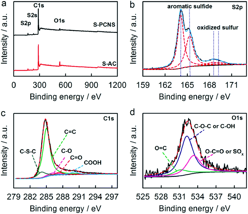 | ||
| Fig. 3 (a) XPS spectra of S-PCNS and S-AC. High resolution XPS spectrum of S2p (b), C1s (c) and O1s (d) for S-PCNS. | ||
Fig. 4 shows the nitrogen adsorption–desorption isotherms and pore size distribution of S-PCNS and S-AC. The N2 adsorption at low relative pressures (P/P0 < 0.1) and distinct hysteresis loops (P/P0 > 0.45) at high relative pressures can be observed for all samples, indicating the presence of both micropores and mesopores. Textural properties of S-PCNS and S-AC are listed in Table S2 (see ESI†). The S-PCNS show a high Brunauer–Emmett–Teller (BET) surface area of 2005 m2 g−1, a micropore area of 585 m2 g−1, a total pore volume of 1.21 cm3 g−1, and a micropore volume of 0.33 cm3 g−1. The graphitization can decrease the surface areas of carbon materials, so the BET surface area of S-PCNS is a little lower than that of S-AC (2172 m2 g−1). The pore size distribution of the S-PCNS shows that abundant micropores and mesopores exist in the range of 0.5–2 and 2–10 nm, respectively, with an average pore diameter of 2.5 nm. It is obvious that the high specific surface area is mainly attributed to the formation of porous structure resulting from KOH activation. As reported, the activation of carbon with KOH proceeds as 6KOH + C ↔ 2K + 3H2 + 2K2CO3, followed by decomposition of K2CO3 and/or reaction of K/K2CO3/CO2 with carbon, which yields abundant pores in the carbon products.41–44
 | ||
| Fig. 4 Nitrogen adsorption–desorption isotherms (a) and pore distribution (b) of S-PCNS and S-AC. | ||
Electrochemical performance of S-PCNS as the electrode materials for supercapacitors was estimated by a symmetrical two-electrode configuration in 6 M KOH aqueous solution. As shown in Fig. 5a, cyclic voltammograms of S-PCNS retain a relatively rectangular shape without a very oblique angle even at a scan rate as high as 1000 mV s−1, indicating the highly capacitive nature with rapid charging–discharging characteristics. Fig. 5b shows charge–discharge curves of S-PCNS at different current densities. For comparison, galvanostatic charge–discharge measurements for S-AC were also carried out (Fig. S5, see ESI†). The discharge curves of S-PCNS are highly symmetrical to their corresponding charge counterparts, indicating high charge–discharge efficiency (nearly 100%). Specific capacitances of both samples at different current densities are presented in Fig. 5c. The specific capacitances of S-PCNS calculated from discharge curves at 0.5 A g−1 are 312 F g−1. Although S-AC has higher BET surface area than S-AC, the specific capacitance of S-AC (225 F g−1 at 0.5 A g−1) is much lower than that of S-PCNS. The high capacitance performance of S-PCNS can be attributed to the ultrathin graphitic nanosheet structure. The thickness of S-PCNS is only ∼4 nm, which is much thinner than that of S-AC. So the surface area of S-PCNS can be fully exposed to electrolyte, resulting in little useless surface areas. In addition, the S-PCNS have higher graphitization degree than the S-AC, which facilitating rapid electron transfer. Moreover, as listed in Table S3 (see ESI†), the specific capacitance of S-PCNS is also higher than those of most sulfur doped carbons and graphene materials in aqueous media reported previously. The specific capacitances of S-PCNS progressively decrease with the increase of the current density from 0.5 to 50 A g−1. However, the specific capacitance of S-PCNS at 50 A g−1 still retain high value of 247 F g−1, which are 78% of the value at 0.5 A g−1. From the above discussion, it can be seen that the S-PCNS can show both high specific capacitance and excellent rate capability. To confirm the effect of sulfur on the performance of S-PCNS, sulfur-free porous carbon nanosheets (denoted as PCNS) were synthesized using cobalt ion-impregnated D113-type ion exchange resin as the carbon precursor. The PCNS was synthesized similarly as the S-PCNS except that a D113-type ion exchange resin was used instead. As shown in Fig. S6 (see ESI†), the PCNS shows similar structure and comparable specific surface area (1998 m2 g−1) with the S-PCNS, but contains no sulfur component. The specific capacitances of the S-PCNS at different current densities are higher than those of the PCNS, highlighting the advantage of sulfur doping. The increase in specific capacitance by sulfur doping is related to the high electron density located at the surface of carbon material due to the presence of the aromatic sulfide, which increases the electrolyte dielectric constant and facilitates the charge transfer process.34
 | ||
| Fig. 5 (a) Cyclic voltammograms of S-PCNS in 6 M KOH aqueous solution at different scan rates. (b) Galvanostatic charge–discharge curves of S-PCNS at different current densities. (c) Specific capacitance of S-PCNS and S-AC at different current densities. (d) Nyquist plots of supercapacitors with different electrode materials performed in 6 M KOH aqueous solution. Inset shows the enlarged high-frequency region. | ||
The fast ion and electron transfer for S-PCNS-based supercapacitor is further confirmed by the Nyquist plot. As shown in Fig. 5d, the Nyquist plot shows a short Warburg-type line (the slope of the 45° portion of the curve), suggesting fast ion diffusion in S-PCNS-based electrodes. The low-frequency segment of the impedance spectrum was nearly vertical, indicating a nearly ideal capacitor behaviour. The equivalent series resistance (ESR), an important parameter determining the charged–discharged rate of a supercapacitor, is comprised of the electrode resistance, electrolyte resistance and resistance due to the diffusion of ions in the electrode porosity, which can be obtained from the intercept of the plot with the real impedance axis. The ESR value of S-PCNS is estimated to be 0.30 Ω, which is much smaller than that of S-AC (1.3 Ω). The small ESR of S-PCNS should suggest a fast ion and electron transfer. The large ESR of S-AC may be attributed to the relatively lower electric conductivity resulting from the poor graphitization degree.
The power density and energy density are calculated using the galvanostatic charge–discharge data. Fig. 6 shows the Ragone plots for S-PCNS and S-AC-based supercapacitors. The specific energy density of S-PCNS is as high as 11.0 W h kg−1 at 0.5 A g−1, which is much higher than that S-AC (7.8 W h kg−1). More importantly, the specific energy densities of S-PCNS are still as high as 7.40 W h kg−1 with high specific power densities (P) of 21.6 kW kg−1 at a high current density of 50 A g−1. These results indicate that the S-PCNS-based supercapacitor can operate with high power density and high energy density at high rates. The stability of the S-PCNS-based supercapacitor was evaluated by examination of 10000 cycles at a galvanostatic charge–discharge current density of 2 A g−1. As shown in Fig. 7, the triangular shape of the galvanostatic charge–discharge curve changes little after 10000 cycles. After continuous charge–discharge for 10000 cycles, the S-PCNS-based supercapacitor still retained ∼97% of its initial specific capacitance, indicating its excellent cycling stability.
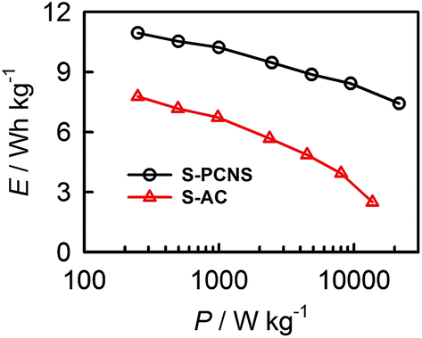 | ||
| Fig. 6 Ragone plots for S-PCNS and S-AC-based supercapacitors. | ||
 | ||
| Fig. 7 (a) The charge–discharge curves of the supercapacitor with S-PCNS as electrode material before and after 10000 cycles at 2 A g−1. (b) Capacitance retention versus the cycle number measured at 2 A g−1. | ||
Conclusions
In summary, we have successfully prepared a novel S-PCNS by direct carbonization and simultaneous chemical activation of cobalt ion-impregnated sulfonic acid ion exchange resin. The S-PCNS showed 3D interconnected structure, high graphitization degree, high content of sulfur doping, high specific surface area, and good porosity. These features provide S-PCNS with excellent capacitance properties, such as high specific capacitance, excellent rate capability, high energy density, and outstanding cycling stability, indicating a potential electrode material for supercapacitors. The S-PCNS with unique structure and composition may be suitable for many other applications such as Li-ion batteries, H2 storage, CO2 capture, and fuel desulfurization.Acknowledgements
This work is supported by NSFC (21305041, 21275052), Scientific Research Fund of Hunan Provincial Education Department (13B063), and Start-Up Fund for Young Teachers in Hunan Normal University. W. Deng and Y. Zhang contributed equally to this work.References
- M. Winter and R. J. Brodd, Chem. Rev., 2004, 104, 4245–4269 CrossRef CAS.
- J. R. Miller and P. Simon, Science, 2008, 321, 651–652 CrossRef CAS PubMed.
- P. Simon and Y. Gogotsi, Nat. Mater., 2008, 7, 845–854 CrossRef CAS PubMed.
- Y. Huang, J. Liang and Y. Chen, Small, 2012, 8, 1805–1834 CrossRef CAS PubMed.
- J. R. Miller, R. A. Outlaw and B. C. Holloway, Science, 2010, 329, 1637–1639 CrossRef CAS PubMed.
- M. D. Stoller and R. S. Ruoff, Energy Environ. Sci., 2010, 3, 1294–1301 CAS.
- P. J. Hall, M. Mirzaeian, S. I. Fletcher, F. B. Sillars, A. J. R. Rennie, G. O. Shitta-Bey, G. Wilson, A. Cruden and R. Carter, Energy Environ. Sci., 2010, 3, 1238–1251 CAS.
- M. D. Stoller, S. J. Park, Y. W. Zhu, J. H. An and R. S. Ruoff, Nano Lett., 2008, 8, 3498–3502 CrossRef CAS PubMed.
- L. L. Zhang and X. S. Zhao, Chem. Soc. Rev., 2009, 38, 2520–2531 RSC.
- Y. Zhai, Y. Dou, D. Zhao, P. F. Fulvio, R. T. Mayes and S. Dai, Adv. Mater., 2011, 23, 4828–4850 CrossRef CAS PubMed.
- K. Xie, X. Qin, X. Wang, Y. Wang, H. Tao, Q. Wu, L. Yang and Z. Hu, Adv. Mater., 2012, 24, 347–352 CrossRef CAS PubMed.
- Z. S. Wu, D. W. Wang, W. Ren, J. Zhao, G. Zhou, F. Li and H. M. Cheng, Adv. Funct. Mater., 2010, 20, 3595–3602 CrossRef CAS.
- S. Chen, J. Zhu, X. Wu, Q. Han and X. Wang, ACS Nano, 2010, 4, 2822–2830 CrossRef CAS PubMed.
- C. Yuan, L. Yang, L. Hou, L. Shen, X. Zhang and X. W. Lou, Energy Environ. Sci., 2012, 5, 7883–7887 CAS.
- J. Yan, Z. Fan, W. Sun, G. Ning, T. Wei, Q. Zhang, R. Zhang, L. Zhi and F. Wei, Adv. Funct. Mater., 2012, 22, 2632–2641 CrossRef CAS.
- M. Xue, F. Li, J. Zhu, H. Song, M. Zhang and T. Cao, Adv. Funct. Mater., 2012, 22, 1284–1290 CrossRef CAS.
- F. Huang and D. Chen, Energy Environ. Sci., 2012, 5, 5833–5841 CAS.
- J. Liu, J. Sun and L. Gao, J. Phys. Chem. C, 2010, 114, 19614–19620 CAS.
- E. Frackowiak and F. Béguin, Carbon, 2001, 39, 937–950 CrossRef CAS.
- Y. Tan, C. Xu, G. Chen, Z. Liu, M. Ma, Q. Xie, N. Zheng and S. Yao, ACS Appl. Mater. Interfaces, 2013, 5, 2241–2248 CAS.
- L. Hu, J. W. Choi, Y. Yang, S. Jeong, F. L. Mantia, L. F. Cui and Y. Cui, Proc. Natl. Acad. Sci. U. S. A., 2009, 106, 21490–21494 CrossRef CAS PubMed.
- S. T. Mayer, R. W. Pekala and J. L. Kaschmitter, J. Electrochem. Soc., 1993, 140, 446–451 CrossRef CAS PubMed.
- C. Liu, Z. Yu, D. Neff, A. Zhamu and B. Z. Jang, Nano Lett., 2010, 10, 4863–4868 CrossRef CAS PubMed.
- X. Yang, J. Zhu, L. Qiu and D. Li, Adv. Mater., 2011, 23, 2833–2838 CrossRef CAS PubMed.
- J. Liu, L. Zhang, H. B. Wu, J. Lin, Z. Shen and X. W. Lou, Energy Environ. Sci., 2014, 7, 3709–3719 CAS.
- C. X. Guo and C. M. Li, Energy Environ. Sci., 2011, 4, 4504–4507 CAS.
- W. Gu, M. Sevilla, A. Magasinski, A. B. Fuertes and G. Yushin, Energy Environ. Sci., 2013, 6, 2465–2476 CAS.
- L. F. Chen, X. D. Zhang, H. W. Liang, M. Kong, Q. F. Guan, P. Chen, Z. Y. Wu and S. H. Yu, ACS Nano, 2012, 6, 7092–7102 CrossRef CAS PubMed.
- F. Su, C. K. Poh, J. S. Chen, G. Xu, D. Wang, Q. Li, J. Lin and X. W. Lou, Energy Environ. Sci., 2011, 4, 717–724 CAS.
- M. Zhong, E. K. Kim, J. P. McGann, S.-E. Chun, J. F. Whitacre, M. Jaroniec, K. Matyjaszewski and T. Kowalewski, J. Am. Chem. Soc., 2012, 134, 14846–14857 CrossRef CAS PubMed.
- D. Hulicova-Jurcakova, M. Kodama, S. Shiraishi, H. Hatori, Z. H. Zhu and G. Q. Lu, Adv. Funct. Mater., 2009, 19, 1800–1809 CrossRef CAS.
- D. Zhang, Y. Hao, L. Zheng, Y. Ma, H. Feng and H. Luo, J. Mater. Chem. A, 2013, 1, 7584–7591 CAS.
- W. Si, J. Zhou, S. Zhang, S. Li, W. Xing and S. Zhuo, Electrochim. Acta, 2013, 107, 397–405 CrossRef CAS PubMed.
- X. Zhao, Q. Zhang, C.-M. Chen, B. Zhang, S. Reiche, A. Wang, T. Zhang, R. SchlÖgl and D. S. Su, Nano Energy, 2012, 1, 624–630 CrossRef CAS PubMed.
- K. Singh, M. Seredych, E. R. Castellon and T. J. Bandosz, ChemElectroChem, 2014, 1, 565–572 CrossRef.
- M. Seredych, K. Singh and T. J. Bandosz, Electroanalysis, 2014, 26, 109–120 CrossRef CAS.
- G. Hasegawa, M. Aoki, K. Kanamori, K. Nakanishi, T. Hanada and K. Tadanaga, J. Mater. Chem., 2011, 21, 2060–2063 RSC.
- M. Seredych and T. J. Bandosz, J. Mater. Chem. A, 2013, 1, 11717–11727 CAS.
- W. Kiciński, M. Szala and M. Bystrzejewski, Carbon, 2014, 68, 1–32 CrossRef PubMed.
- A. H. Lu, W. C. Li, N. Matoussevitch, B. Spliethoff, H. Bönnemann and F. Schüth, Chem. Commun., 2005, 98–100 RSC.
- M. A. Lillo-Rodenas, D. Cazorla-Amoros and A. Linares-Solano, Carbon, 2003, 41, 267–275 CrossRef CAS.
- Y. Zhu, S. Murali, M. D. Stoller, K. J. Ganesh, W. Cai, P. J. Ferreira, A. Pirkle, R. M. Wallace, K. A. Cychosz, M. Thommes, D. Su, E. A. Stach and R. S. Ruoff, Science, 2011, 332, 1537–1541 CrossRef CAS PubMed.
- Y. Li, Z. Li and P. K. Shen, Adv. Mater., 2013, 25, 2474–2480 CrossRef CAS PubMed.
- Y. Zhang, M. Chu, L. Yang, W. Deng, Y. Tan, M. Ma and Q. Xie, Chem. Commun., 2014, 50, 6382–6385 RSC.
Footnote |
| † Electronic supplementary information (ESI) available: The percentage of various elements obtained from XPS data, textural properties of S-PCNS and S-AC, comparison of the specific capacitance of S-PCNS with literature, AFM characterization of S-PCNS, SEM and TEM characterization of S-AC, TEM images of cobalt ion-impregnated sulfonic acid ion exchange resin after pyrolysis and acid leaching, high resolution XPS spectrum of S2p peak for S-AC, cyclic voltammograms and galvanostatic charge–discharge curves of S-AC, characterization of PCNS. See DOI: 10.1039/c4ra14820g |
| This journal is © The Royal Society of Chemistry 2015 |