A hybrid catalyst composed of reduced graphene oxide/Cu2S quantum dots as a transparent counter electrode for dye sensitized solar cells

Enbing Bia, Yanjie Sub, Han Chen*a, Xudong Yanga, Maoshu Yina, Fei Yea, Zhongli Lib and Liyuan Han*ac
aState Key Laboratory of Metal Matrix Composites, School of Materials Science and Engineering, Shanghai Jiao Tong University, Shanghai 200240, PR China. E-mail: chen.han@sjtu.edu.cn; Fax: +86 21 54742414; Tel: +86 21 54742414
bKey Laboratory for Thin Film and Microfabrication of the Ministry of Education, Institute of Micro/Nano Science and Technology, Shanghai Jiao Tong University, Shanghai 200240, PR China. Fax: +86 21 3420 5665; Tel: +86 21 3420 5665
cPhotovoltaic Materials Unit, National Institute for Materials Science (NIMS), Tsukuba, Ibaraki 305-0047, Japan. E-mail: HAN.Liyuan@nims.go.jp; Fax: +81 29 859 2304

Received 7th November 2014 , Accepted 22nd December 2014

First published on 23rd December 2014


Abstract

We synthesized a hybrid catalyst of reduced graphene oxide/Cu2S quantum dots (RGO/Cu2S QDs) via a facile wet chemical approach. The synergistic effect between ultrathin-RGO and ultrasmall-QDs endowed the hybrid catalyst with a high transparent performance, excellent conductivity and catalytic activity. A dye-sensitized solar cell fabricated with the hybrid catalyst showed the overall power conversion efficiency was 7.12%, which was comparable to that of a Pt-based device.

Dye-sensitized solar cells (DSSCs) are promising devices for low-cost and large-area photovoltaic applications because DSSCs can be fabricated by inexpensive and easily processible materials.1,2 A standard DSSC consists three main parts: a dye-sensitized TiO2 photoanode, an iodide/triiodide (I/I3) redox couple, and a counter electrode (CE). The CE serves as a redox-catalyst for the regeneration of the reduction couple.3,4 Platinum (Pt) is the preferred catalyst material for the reduction of I3, owing to its excellent conductivity and catalytic activity. However, its high cost and low abundance seriously hinder large-scale commercialization of Pt-based DSSCs. This has fostered the development of low-cost Pt-alternative materials and high-throughput technologies such as screen-printing, roll-to-roll printing, and spraying coating.

Additionally, transparent DSSCs would be more preferable for use in power-generating windows and decorative installations, especially in the construction of integrated photovoltaic systems. The search for highly transparent catalyst materials has led to numerous fundamental breakthroughs. Materials ranging from various types carbon-based materials5,6 to conductive polymers,7 to inorganic compounds8 have been employed as low-cost CEs for the DSSCs. Several effective routes have been developed to improve the transparency of CEs. Transparent, conductive, and ultrathin graphene film was the first alternative to be developed to, owing to its high transparency (>70% at wavelength of 1000–3000 nm) and high conductivity (550 S cm−1).9,10 Afterwards, conducting polymers such as poly (3,4-ethylenedioxythiophene) and polyaniline are utilized as transparent CE materials, owing to their extremely low cost and relatively good conductivity. Unfortunately, the poor catalytic performance of carbon materials and unsatisfactory stability of conductive polymers have impeded further improvement in DSSC efficiency using this materials.11,12 Recently, some inorganic nanocrystals were introduced into DSSCs as transparent or semi-transparent catalysts; and owing to the quantum size effects, these materials offer a processible solution for realizing transparent CE that utilizing less mass and thus have a thinner thickness on the conductive substrate. Some important examples include Co9S8,13 Cu2ZnSnS4 (CZTS)14 and FeS2 nanocrystal inks15 spread thinly on fluorine-doped tin oxide (FTO) substrate and result in relatively transparent performance. These nanocrystals are different from the normal micro-structured (>100 nm) catalyst which has less transparency such as hierarchical microspheres: Cu2SnS3 and Cu1.8S, Cu2ZnSnS4.16,17 However, inorganic nanocrystals are typically insulating and this property impedes electron transport in the CEs.18 Various strategies have been developed to improve the electrical conductivity, including optimizing nanocrystal size, designing novel nanostructures and modifying rational composition.19,20 Currently, fabricating nanocrystals/carbon is a promising solution to boost the conductivity and catalytic activity at same time.21 Hierarchical Cu2S microspheres wrapped by reduced graphene oxide nanosheets as a counter electrode showed better electrocatalytic activity and higher exchanges current density.22 In addition, nickel phosphide-embedded in graphene presented an excellent performance, competing with that of the typical Pt counter electrode.23 Recently we have synthesized a novel core–shell catalyst composed of the nitrogen-doped graphene as high performance conductive path shelled on CoS nanocrystal and the resulting DSSC efficiency was 10.7% which was comparable to the Pt.24 Unfortunately, the counter electrodes based on these materials are opaque due to its high thickness to ensure the catalytic activity.

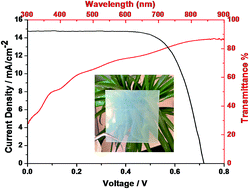
In this study, we demonstrated a hybrid catalyst composed of reduced graphene oxide/Cu2S quantum dots as a transparent CE for DSSC. Owing to the synergistic effect between ultrathin-RGO and ultrasmall-QDs, the counter electrode based on the hybrid catalyst displayed highly transparent performance, excellent conductivity, and catalytic activity. Meanwhile, with regard to above advantages, the DSSC based on this hybrid catalyst achieved the efficiency of 7.12%, which is comparable to that of Pt device (7.38%).

The hybrid catalyst was synthesized according to our previous report via a facile wet chemical approach involving the assembly of Cu2S QDs on RGO layers.25 In this process, the oleylamine (OLA) complexed with the Cu ions and, more importantly, reduced GO into RGO (see the ESI in details). For comparison, the Cu2S QDs were synthesized without RGO.

It was known that ultrathin graphene nanosheet is benefiting for electron transfer and transparency improvement. The graphene was 1.834 nm thickness confirmed by the AFM and TEM images in the Fig. S1b and c, which indicates that it can serve as a novel substrate for Cu2S QDs. Through the facile assembly wet chemical approach, the Cu2S QDs uniformly decorated on the graphene with a size distribution in the range of 6–8 nm (Fig. 1a), corresponding to pure Cu2S QDs (Fig. S1a). From a high-resolution transmission electron microscopy imagine (Fig. 1b), we determined that the lattice spacing of the Cu2S QDs is 0.2 nm, which corresponds to the (220) plane of the Cu2S face-centred cubic (fcc) lattice. The selected-area electron diffraction (SAED) pattern (in inset of Fig. 1d) exhibited sharp diffraction rings, a result that agrees well with the specific crystalline planes of the Cu2S QDs on the graphene, and indicates that the Cu2S QDs are randomly on the graphene sheets and were polycrystalline.25 Energy dispersive spectroscopy (EDS) analysis (Fig. S1d) confirmed that the oxygen content of the as-synthesized hybrid was low, owing to the reduction of GO, and the Cu/S ratio is about 2[thin space (1/6-em)]:[thin space (1/6-em)]1, further supporting the formation of an RGO/Cu2S QDs hybrid.


image file: c4ra14029j-f1.tif
Fig. 1 (a and b) TEM and HRTEM image of RGO/Cu2S QDs hybrid; (c) SEM imagines of Top view and (d) cross-section of RGO/Cu2S QDs hybrid.

The RGO/Cu2S QDs hybrid was deposited on the FTO glass by the means of a spraying coating method which is cost-effective, and large-scale for solution-processed electrode. The as-deposited films were post-treated by annealing at 400 °C under Ar atmosphere for 3 h to improve the mechanical adhesion and remove the surfactants from the Cu2S QDs to increased conductivity.20 A top-view scanning electron microscopy imagine of the hybrid on the FTO glass indicated that the ultra-small Cu2S QDs homogenously distributed on the ultrathin graphene surface (Fig. 1c). However, the pure Cu2S QDs agglomerated to form large non-uniform particles (Fig. S2a), which indicates the ultrathin graphene can serve a novel substrate to prevent Cu2S QDs agglomeration in the RGO/Cu2S hybrid. The thickness of RGO/Cu2S hybrid on FTO glass is in the range of 0.3–0.5 μm measured by a surface profiler (Fig. S3), which controlled by the spraying time. Cross-sectional scanning electron microscopy image (Fig. 1d) showed that RGO/Cu2S QDs layer seamlessly adhered to the FTO substrate, which was beneficial for the conductivity improvement.

We measured the photoluminescence (PL) spectra of the RGO/Cu2S QDs hybrid and the pure Cu2S QDs (Fig. 2a). The PL intensity of the RGO/Cu2S hybrid was too weak to be identified, as has been reported previously for other semiconductor RGO/QDs hybrids; the weak photoluminescence has been attributed to photo-induced electron transfer from the Cu2S QDs to the RGO sheets, which hampered the radioactive recombination of electron–hole pairs and results in photoluminescence quenching.26,27 Moreover, the pure Cu2S QDs exhibited high performance PL intensity compared to RGO/Cu2S hybrids. This confirmed the ultrathin RGO provided a novel electron-transfer path for electron from Cu2S QDs to graphene.


image file: c4ra14029j-f2.tif
Fig. 2 (a) Photoluminescence spectra of RGO/Cu2S QDs hybrid and the Cu2S QDs. (b) UV-vis transmission spectra of RGO-Cu2S QDs hybrid, Cu2S QDs, RGO, and Pt electrodes.

The UV-vis transmission spectra of RGO/Cu2S QDs hybrid, Cu2S QDs, RGO and Pt electrodes on FTO glass were further characterized (Fig. 2b); the spectrum of pure FTO glass was used as the reference. The RGO/Cu2S QDs hybrid and Cu2S QDs electrodes exhibited high transmittance at visible wavelengths. The average transmittance of as-prepared RGO/Cu2S QDs hybrid electrode is more than about 60% in the wavelength range of 400–800 nm, which has the semitransparent light transmittance performance. This is due mainly to the fact that both the ultra-small Cu2S QDs and the ultra-thin graphene sheets have high transmittance at the visible wavelengths, which is helpful to the fabrication of transparent electrode for DSSCs.

In addition to the transparency, the catalytic activity and conductivity of the counter electrode is also of great importance for a high performance counter electrode. We performed cyclic voltammetry (CV), electrochemical impedance spectroscopy (EIS) and Tafel methods to evaluate the catalytic activity and conductivity of counter electrode. In the CV curves of RGO/Cu2S QDs hybrid, Cu2S QDs, RGO and Pt electrodes (Fig. 3a), two typical pairs of oxidation and reduction peaks (Ox-1/Red-1 and Ox-2/Red-2) were observed for all the electrodes except the RGO electrode. The characteristics of peaks Ox-1 and Red-1, which are the focus of our analysis, should be noted because the CE of a DSSC is responsible for catalyzing the reduction of I3 to I.28,29 The RGO/Cu2S QDs hybrid electrode showed an Epp value of 0.51 V (Table 1), which was comparable to that of the Pt electrode and substantially lower than Cu2S QDs, indicating that RGO/Cu2S hybrid was a remarkable electrochemical catalyst for the reduction of I3. This result may ascribe to a positive synergetic effect between the RGO and Cu2S QDs on reduction of I3 to I.


image file: c4ra14029j-f3.tif
Fig. 3 (a) Cyclic voltammograms for RGO/Cu2S QDs hybrid, Cu2S QDs, RGO and Pt electrodes; (b) Nyquist plots and (c) Tafel curves of the symmetrical cells fabricated with two identical electrodes; (d) photocurrent-voltage curves of the DSSCs using RGO/Cu2S QDs hybrid, Cu2S QDs, RGO and Pt electrodes.
Table 1 The detailed photovoltaic performance of the DSSCs using different CEs and the simulated data from CV and EIS spectra
CEs JSC mA cm2 VOC mV FF η% Rs Ω Rct Ω Epp V
RGO/Cu2S 14.45 712 0.69 7.12 15.65 3.24 0.51
Cu2S 12.86 693 0.59 5.21 21.17 6.93 0.93
RGO 11.25 673 0.33 2.52 26.69 33.08
Pt 14.80 702 0.71 7.38 15.22 2.69 0.43


We prepared Nyquist plots for various dummy cells with a sandwich structure (electrode/electrolyte/electrode; Fig. 3b). For a Randles-type circuit, the high-frequency intercept on the real axis represents the series resistance (Rs), the left semicircle in the middle frequency can be attributed to the charge transfer resistance (Rct) at the CE/electrolyte interface, and the right semicircle in the low frequency can be assigned to the diffusion impedance of the redox couple (I/I3) in the electrolyte.12,30 Clearly, the Rs value for RGO/Cu2S QDs hybrid electrode (15.65 Ω) was clearly lower of than the values for the Cu2S QDs and RGO electrodes, and was comparable to the Pt electrode (15.22 Ω), owing to the good adhesion of RGO/Cu2S QDs hybrid to the substrate. Moreover, the Rct value for RGO/Cu2S QDs hybrid electrode was 3.24 Ω, which was comparable to that of Pt electrode and substantially lower than the values for the Cu2S QDs and RGO electrode, which implies that RGO/Cu2S QDs hybrid had the excellent electrocatalytic activity for the reduction of I3.

Furthermore, the Tafel polarization curves demonstrated the charge-transfer properties of I/I3 couple on the electrode surface (Fig. 3c); the Tafel polarization measurements were carried out in the same cell used for the EIS measurement. In the plot of the log of the current density (J) versus potential (U), an anodic or cathodic branch that shows a larger slope implies a higher exchange current density (J0) on the electrode. Comparison of the curves for Cu2S QDs and RGO, the RGO/Cu2S QDs hybrid showed that the curve for RGO/Cu2S QDs hybrid electrode had a larger slope in the Tafel zone, indicating the occurrence of a large exchange current density on the electrode surfaces. This result implies that the catalytic activity achieved with the RGO/Cu2S QDs hybrid was higher than that of the other electrodes and was similar to that of Pt-based electrode.

The photovoltaic performance of alternative counter electrodes based on RGO/Cu2S hybrid, Cu2S QDs, RGO and Pt was evaluated by fabricating nanocrystalline DSSCs using the N719 sensitizer and I/I3 redox couple.31 The photocurrent density–voltage (JV) curves of DSSCs under irradiation at 100 mW cm−2 based on the different CEs are shown in Fig. 3d and the detailed photovoltaic parameters are summarized in the Table 1. The short-circuit current density (JSC), open-circuit potential (VOC) and fill factor (FF) the cell with the RGO/Cu2S QDs hybrid CEs were 14.45 mA cm−2, 712 mV and 0.69, resulting an overall power conversion efficiency (η) of 7.12%, which was comparable to that of the corresponding Pt-based device. The η value dropped to 5.21% when pure Cu2S QDs were used in the CE owing to a lower fill factor (0.59) and JSC (12.86 mA cm−2), which may have been the result of poor electron-transfer activity. This result indicates that the combination of RGO and the Cu2S QDs endowed the hybrid counter electrode with a superb performance that was due to low resistance and high electrocatalytic activity.

Conclusions

In summary, we demonstrated for the first time that an RGO/Cu2S QDs hybrid is an effective transparent catalyst for the reduction of I3 to I in DSSCs, as indicated by CV, EIS, and Tafel polarization measurements. The hybrid catalyst of RGO/Cu2S QDs exhibits excellent catalytic activity and conductivity. A DSSC device based on the hybrid catalyst showed an overall power conversion efficiency of 7.12%, which can be comparable to that a DSSC with Pt-based CE (7.38%). The approach of utilizing the synergistic effect between ultrathin-RGO and ultrasmall-QDs in this work provides a promising strategy to replace the traditional noble Pt, achieve high-efficiency DSSCs, as well as may benefit other catalytic, photovoltaic field.

Acknowledgements

We thank the 3rd, 211 project (WS3116205009), Shanghai Jiao Tong University, National Natural Science Foundation of China (no. 51402190), Shanghai Natural Science Foundation (no. 13ZR1456600) and Core Research for Evolutional Science and Technology of the Japan Science and Technology Agency (CREST).

Notes and references

  1. B. O'regan and M. Grfitzeli, Nature, 1991, 353, 737–740 CrossRef.
  2. A. Yella, H.-W. Lee, H. N. Tsao, C. Yi, A. K. Chandiran, M. K. Nazeeruddin, E. W.-G. Diau, C.-Y. Yeh, S. M. Zakeeruddin and M. Grätzel, Science, 2011, 334, 629–634 CrossRef CAS PubMed.
  3. M. K. Nazeeruddin, F. De Angelis, S. Fantacci, A. Selloni, G. Viscardi, P. Liska, S. Ito, B. Takeru and M. Grätzel, J. Am. Chem. Soc., 2005, 127, 16835–16847 CrossRef CAS PubMed.
  4. Y. Chiba, A. Islam, Y. Watanabe, R. Komiya, N. Koide and L. Han, Jpn. J. Appl. Phys., 2006, 45, L638 CrossRef CAS.
  5. M. Wu, X. Lin, T. Wang, J. Qiu and T. Ma, Energy Environ. Sci., 2011, 4, 2308–2315 CAS.
  6. L. Kavan, J.-H. Yum, M. K. Nazeeruddin and M. Grätzel, ACS Nano, 2011, 5, 9171–9178 CrossRef CAS PubMed.
  7. J. Kwon, V. Ganapathy, Y. H. Kim, K.-D. Song, H.-G. Park, Y. Jun, P. J. Yoo and J. H. Park, Nanoscale, 2013, 5, 7838–7843 RSC.
  8. M. Wang, A. M. Anghel, B. t. Marsan, N.-L. Cevey Ha, N. Pootrakulchote, S. M. Zakeeruddin and M. Grätzel, J. Am. Chem. Soc., 2009, 131, 15976–15977 CrossRef CAS PubMed.
  9. X. Wang, L. Zhi and K. Müllen, Nano Lett., 2008, 8, 323–327 CrossRef CAS PubMed.
  10. L. Kavan, J. H. Yum and M. Grätzel, ACS Nano, 2010, 5, 165–172 CrossRef PubMed.
  11. S. Ahmad, J.-H. Yum, Z. Xianxi, M. Grätzel, H.-J. Butt and M. K. Nazeeruddin, J. Mater. Chem., 2010, 20, 1654–1658 RSC.
  12. Q. Tai, B. Chen, F. Guo, S. Xu, H. Hu, B. Sebo and X.-Z. Zhao, ACS Nano, 2011, 5, 3795–3799 CrossRef CAS PubMed.
  13. S.-H. Chang, M.-D. Lu, Y.-L. Tung and H.-Y. Tuan, ACS Nano, 2013, 7, 9443–9451 CrossRef CAS PubMed.
  14. X. Xin, M. He, W. Han, J. Jung and Z. Lin, Angew. Chem., Int. Ed., 2011, 50, 11739–11742 CrossRef CAS PubMed.
  15. Y. C. Wang, D. Y. Wang, Y. T. Jiang, H. A. Chen, C. C. Chen, K. C. Ho, H. L. Chou and C. W. Chen, Angew. Chem., Int. Ed., 2013, 52, 6694–6698 CrossRef CAS PubMed.
  16. J. Xu, X. Yang, T. L. Wong and C. S. Lee, Nanoscale, 2012, 4, 6537–6542 RSC.
  17. J. Xu, X. Yang, Q. D. Yang, T. L. Wong and C. S. Lee, J. Phys. Chem. C, 2012, 116, 19718–19723 CAS.
  18. D. Y. Wang, Y. T. Jiang, C. C. Lin, S. S. Li, Y. T. Wang, C. C. Chen and C. W. Chen, Adv. Mater., 2012, 24, 3415–3420 CrossRef CAS PubMed.
  19. Y.-F. Du, J.-Q. Fan, W.-H. Zhou, Z.-J. Zhou, J. Jiao and S.-X. Wu, ACS Appl. Mater. Interfaces, 2012, 4, 1796–1802 CAS.
  20. L. Yi, Y. Liu, N. Yang, Z. Tang, H. Zhao, G. Ma, Z. Su and D. Wang, Energy Environ. Sci., 2013, 6, 835–840 CAS.
  21. Y. Liang, Y. Li, H. Wang, J. Zhou, J. Wang, T. Regier and H. Dai, Nat. Mater., 2011, 10, 780–786 CrossRef CAS PubMed.
  22. M. Ye, C. Chen, N. Zhang, X. Wen, W. Guo and C. Lin, Adv. Energy Mater., 2014 DOI:10.1002/aenm.201301564.
  23. Y. Y. Dou, G. R. Li, J. Song and X. P. Gao, Phys. Chem. Chem. Phys., 2012, 14, 1339–1342 RSC.
  24. E. Bi, H. Chen, X. Yang, W. Peng, M. Grätzel and L. Han, Energy Environ. Sci., 2014, 7, 2637–2641 CAS.
  25. Y. Su, X. Lu, M. Xie, H. Geng, H. Wei, Z. Yang and Y. Zhang, Nanoscale, 2013, 5, 8889–8893 RSC.
  26. I. V. Lightcap and P. V. Kamat, J. Am. Chem. Soc., 2012, 134, 7109–7116 CrossRef CAS PubMed.
  27. D. Zhang, L. Gan, Y. Cao, Q. Wang, L. Qi and X. Guo, Adv. Mater., 2012, 24, 2715–2720 CrossRef CAS PubMed.
  28. J. Song, G. R. Li, C. Y. Wu and X. P. Gao, Metal sulfide counter electrodes for dye-sensitized solar cells: a balanced strategy for optical transparency and electrochemical activity, J. Power Sources, 2014, 266, 464–470 CrossRef CAS PubMed.
  29. G. R. Li, J. Song, G. L. Pan and X. P. Gao, Energy Environ. Sci., 2011, 4, 1680–1683 CAS.
  30. Q. W. Jiang, G. R. Li and X. P. Gao, Chem. Commun., 2009, 6720–6722 RSC.
  31. X. Yang, M. Yanagida and L. Han, Energy Environ. Sci., 2013, 6, 54–66 CAS.

Footnote

Electronic supplementary information (ESI) available: Preparation of RGO/Cu2S QDs hybrid; fabrication of DSSCs and fabrication of DSSCs and symmetrical cells and characterization. See DOI: 10.1039/c4ra14029j

This journal is © The Royal Society of Chemistry 2015
Click here to see how this site uses Cookies. View our privacy policy here.