Ni-enhanced Co3O4 nanoarrays grown in situ on a Cu substrate as integrated anode materials for high-performance Li-ion batteries

Xiaoyu Liu ab, Shimou Chenb, Jia Yub, Wenlong Zhanga, Yajie Dai*a and Suojiang Zhang*b
aSchool of Electrical and Electronic Engineering, Harbin University of Science and Technology, Harbin, Heilongjiang 150040, PR China. E-mail: yajiedai@yeah.net
bBeijing Key Laboratory of Ionic Liquids Clean Process, Key Laboratory of Green Process and Engineering, Institute of Process Engineering (IPE), Chinese Academy of Sciences (CAS), Beijing 100190, PR China. E-mail: sjzhang@home.ipe.ac.cn

Received 6th November 2014 , Accepted 19th December 2014

First published on 19th December 2014


Abstract

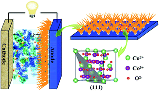
A two-step strategic approach was proposed to synthesize three-dimensional Co3O4 nanoarrays fabricated on a Cu substrate surface with a Ni layer as the interface. Firstly, a Ni-nanoseed-layer was prepared on a Cu substrate by electrodepositing Ni. And then Co3O4 nanoarrays were in situ grown on the Ni layer via a hydrothermal synthesis. The as-obtained materials were used directly as anodes for Li-ion batteries, and the electrodes maintained a high capacity up to 1150 mA h g−1 at 0.1 C after 30 cycles, and showed an excellent cycling stability and rate capability. The good electrochemical performance is owing to the pre-electrodeposited Ni-nanoseed-layer, because the Ni layer could improve the mechanical adhesion between Co3O4 nanoarrays and substrates effectively and increase the conductivity of anodes, without applying binders or conductive additives. This strategic in situ synthesis method will probably open a new avenue for the development of integrated electrode materials for high-performance Li-ion batteries.


Introduction

Along with the rapid development of economies and societies, new energy-materials are extensively used in many areas, including portable electronics, electric vehicles, and smart grids.1–4 Therefore research on battery materials with high capacity, cycling stability and security is necessary. As the Li-ion battery (LIB) has many advantages including high energy density, large output power, and friendly to the environment, it plays an irreplaceable role in the secondary energy supply.5–8 Transition-metal oxide materials such as cobalt oxide and nickel oxide are promising high-energy-density anode materials. Among them cobalt-based electrode materials are attractive due to their high electrochemical activity and ease of processing,9 and Co3O4 as anode material has attracted more interest owing to its superior specific capacity (896 mA h g−1 in theory),10–13 which is much higher than that of commercial graphite anode (∼372 mA h g−1). However, relatively poor capacity retention upon cycling and low rate capability of Co3O4 restrict its practical application in LIBs as a high-performance anode. Different approaches have been utilized to improve the electrochemical properties of Co3O4, such as the use of Co3O4/carbon nanocomposites, nanoscale Co3O4 and mesoporous Co3O4. In addition to the above approaches, considerable effort has been devoted to develop Co3O4 materials with three-dimensional (3D) microstructure,14 since the unique morphology can significantly enhance electrochemical performance: (1) the 3D microstructure provide better access for Li ions due to a larger electrode/electrolyte interface, and shorter diffusion paths for Li ions and electrons, leading to improved rate capability.15,16 (2) The free space among nanoarrays can effectively buffer the large volume change during Li insertion/extraction, thus contribute to better cycling stability.17,18 (3) The 3D nanoarrays show stable structural support and multiple interconnections across nanowires.

Besides the 3D nanoarray microstructure, we inferred that if Co3O4 nanoarrays could be in situ grown on the current collector while maintaining a good contact, it would show better cycling performance and durability when used as LIB anode materials directly. Considering the low-cost Cu sheets are common current collecting substrates, we proposed that 3D Co3O4 nanoarrays fabricated on Cu substrates are promising anode materials, since this integrated anode can enhance electrical conductivity and enlarge reaction surface.19–21 However, free-standing Co3O4 nanoarrays grown directly on Cu sheets have rarely been realized.22 As the adhesion between nanoarrays and Cu substrates is weak, active materials are easy to fall off during the charging–discharging process, thus greatly reduces the cycling stability and energy density.

In this paper, we successfully prepared Ni-enhanced Co3O4 nanoarrays in situ grown on Cu substrate as integrated anode for high-performance LIBs, by a two-step approach. The new synthetic strategy combined two synthesis methods of electrodeposition of Ni-nanoseed-layer and hydrothermal synthesis. We found that pre-electrodepositing Ni-nanoseed-layer onto the Cu substrate could improve the mechanical adhesion between Co3O4 nanoarrays and substrates effectively and increase the conductivity of anodes, without applying binders or conductive additives. Those were the principal reasons for improved performance. In addition, we preliminarily speculated that the Ni layer might play some role in influencing the growth of Co3O4 nanoarrays, promoting the formation of nanoarrays with dominant (111) crystal planes that show much better performance than (001) planes.23 Finally, when as-obtained Ni-enhanced Co3O4 nanoarrays were investigated as anode materials for LIBs, these integrated electrodes indeed exhibited good specific capacity, cycling stability and rate capability.

Experimental

Electrodeposition of Ni nanoseeds

Firstly, we carefully cleaned the Cu sheet in mixed acid solution for 5 min in order to remove the surface CuO layer, and then used deionized water and ethanol in turn to wash, repeating several times. Subsequently we electrodeposited Ni nanoparticles onto the Cu substrate (1 × 3 cm2 in size). The concentration of plating solution was 250 g L−1 NiSO4·6H2O, 30 g L−1 NiCl2·6HO, 35 g L−1 H3BO3 and 0.1 g L−1 sodium dodecyl sulfate (SDS), while the pH value was set at 3–5. In the three-electrode electrochemical cell, the acid-treated Cu worked as working electrode, Ni plate worked as counter electrode and reference electrode. Electrodepositing Ni was carried out at 45 °C with a stirring speed of 700 rpm, by imposing a constant current. The Ni depositing time was 60 s.

Synthesis of Co3O4 nanoarrays

Co3O4 nanoarrays were prepared by a hydrothermal synthesis method. Firstly, 1.46 g of Co(NO3)2·6H2O, 0.37 g of NH4F and 1.5 g of CO(NH2)2 were dissolved in 50 mL of distilled water. After being stirring slightly for 40 min, the solution was transferred into Teflon-lined stainless steel autoclave. The Cu substrate coated by Ni-nanoseed-layer was immersed into the reaction solution with a tilt angle of 45 degree. The stainless steel autoclave was sealed and heated at 120 °C for 5 h, and then the autoclave was cooled down to room temperature. After the reaction, the samples were rinsed with distilled water for several times. Finally, the Ni-enhanced Co3O4 nanoarrays in situ grown on Cu substrate was obtained after annealing the samples at 450 °C in air for 3 h, with a color changing of the samples from pink to black.

Characterization

The X-ray diffraction (XRD) patterns were recorded on a Bruker D8 Focus X-ray diffractometer with Ni-filtered Cu-Kα radiation (λ = 0.15406 nm). The scanned 2θ range was between 40° and 95° at room temperature. X-ray photoelectron spectroscopy (XPS, PHI 5700), scanning electron microscopy (SEM, JEOL JSM-7001F) and high-resolution transmission electron microscopy (JEOL JEM-2100).

Electrochemical measurements

Simulation of the battery were directly fabricated from the Co3O4–Ni@Cu as the working electrode without any ancillary materials. The electrolyte used was LiPF6 (1 M)/EC + DEC + DMC (1[thin space (1/6-em)]:[thin space (1/6-em)]1[thin space (1/6-em)]:[thin space (1/6-em)]1, weight). The galvanostatic charge–discharge tests were performed using LAND battery testing system in the voltage range of 0.01–3.2 V at room temperature.

Results and discussion

Fig. 1 shows the two-step synthesis strategy for the Co3O4 nanoarrays by the combination of electrodeposition and hydrothermal synthesis. Firstly, Ni nanoparticles were electrodeposited onto the Cu substrate as seeds.24 this sample was named Ni@Cu for simplicity. Subsequently Co3O4 nanoarrays were in situ grown upwards from the Ni-nanoseed-layer on the Cu substrate directly, using hydrothermal synthesis, followed by a calcinations treatment. Impressively, the synthesized integrated anode material showed a high specific capacity, an excellent rate capacity and a good cycling stability.
image file: c4ra13994a-f1.tif
Fig. 1 Schematic for the growth process of Co3O4–Ni@Cu (two-step method).

The as-obtained final products of Ni-enhanced Co3O4 nanoarrays were named Co3O4–Ni@Cu for simplicity. The Energy-dispersive X-ray spectrometry (EDS) mapping analysis shown in Fig. S1 (ESI) proves the existence of the Co3O4–Ni@Cu. The corresponding XRD patterns of Ni@Cu samples are provided in Fig. 2. Fig. 2a and b show the XRD pattern of the Cu substrates after being electrodeposited with Ni layer for 60 s and 200 s, respectively. It was found that the Ni peak was not obvious in a relatively short electrodepositing time, almost all peaks in Fig. 2a belonging to Cu (Fig. 2a). However, when the Ni electrodepositing time reached 200 s, Ni peaks could be observed clearly in Fig. 2b, indicating that the Ni-seed-layer was successfully deposited on the surface of Cu substrate.25,26 Moreover, as shown in Fig. S2 (ESI), the presence of Co3O4, Ni and Cu in Co3O4–Ni@Cu was proved by XRD spectrum.


image file: c4ra13994a-f2.tif
Fig. 2 (a) and (b) XRD patterns of the products after being electrodeposited with Ni, while the electrodepositing time was 60 s and 200 s, respectively. (c) XPS peaks of Ni2p of the Cu substrate after being electrodeposited with Ni (Ni@Cu) and (d) XPS peaks of Co2p of the final product (Co3O4–Ni@Cu).

In order to clarify the components of the final product of Ni-enhanced Co3O4 nanoarrays and find some clues about the growth mechanism, the Ni@Cu and Co3O4–Ni@Cu samples were characterized by XPS. As shown in Fig. 2c, the Ni@Cu sample showed Ni2p3/2 and Ni2p1/2 peaks which are centered at 852.6 and 873.85 eV, respectively, confirming that the elementary Ni was deposited on the surface of Cu substrates. We suggested that Co3O4 nanoarrays were in situ grown from the Ni-nanoseed-layer which was firstly electrodeposited onto Cu substrate. Ni nanoseeds formed a connection layer between the Co3O4 nanoarrays and Cu substrate, playing a key role in stabilizing the nanoarrays grown on Cu substrates. In addition, as seen in Fig. 2d, the Co3O4–Ni@Cu sample exhibited peaks of Co2p1/2 and Co2p3/2 at 795.2 eV and 780.2 eV,8 respectively. The XRD and XPS results indicated that the final product was Ni-enhanced Co3O4 composite.

The morphology of Ni-nanoseed-layer on Cu substrate (Ni@Cu) was shown in Fig. 3a, we observed that the Ni nanoseeds were successfully growth on the Cu substrate. Similarly, Fig. 3b displayed the SEM photograph of 3D Co3O4–Ni@Cu composite nanoarrays, which were electrodeposited with Ni for 60 s and hydrothermal treated at 120 °C for 5 h. The as-obtained Ni-enhanced Co3O4 nanowires had an average diameter of 100 nm. In addition, various steps of formation of layers were proved by color changing (as seen in inset), from silver (Ni@Cu) to black (Co3O4–Ni@Cu).27 In contrast, Fig. S3 (ESI) displayed the SEM images of Co3O4@Cu nanoarrays without Ni nanoseeds. Moreover, too short or too long electrodepositing time was not favorable for the formation of Co3O4–Ni@Cu composite nanoarrays. As shown in Fig. S4 (ESI), when the electrodepositing time was only 2 s, we observed that the Co3O4 nanoarrays were sparser than those with an electrodepositing time of 60 s. By contrast, when the electrodepositing time increased to 6000 s, the anode materials were likely to crack, and Co3O4 active materials were inclined to fall from the Ni-nanoseed-layer.


image file: c4ra13994a-f3.tif
Fig. 3 (a) Low-magnification SEM images of Ni@Cu, the Ni electrodepositing time is 60 s (b)SEM images of the Co3O4–Ni@Cu nanoarrays, the hydrothermal synthesis condition: 120 °C for 5 h. Inset: photographs of the products in different reaction steps.

Further structural characterizations of the Ni-enhanced Co3O4 nanoarrays and Co3O4 nanoarrays without Ni were performed by TEM, as shown in Fig. 4a and c. Obviously, plenty of pores were distributed uniformly on the nanoarray surface due to the gas releasing (CO2, H2O) during the calcination process,28,29 which can provide a quite short diffusion path for Li ions and electrons when used as anode materials for LIBs.30–32 In Fig. 4b which was taken from Co3O4 nanoarrays in situ grown on Cu substrates with Ni-nanoseed-layer, we found that a measured interplanar spacing of 0.467 nm was in good agreement with the spacing of the Co3O4 (111) planes.22 In Fig. 4d which was taken from Co3O4 nanoarrays grown on Cu substrates directly without Ni-nanoseed-layer, it showed a measured interplanar spacing of 0.403 nm which was in good agreement with the spacing of the Co3O4 (001) planes. In general, for HRTEM results we found that Ni-enhanced Co3O4 nanoarrays had dominant (111) crystal planes while Co3O4 nanoarrays without Ni-nanoseed-layer showed dominant (001) crystal planes. Moreover, in previous work, addition of seed layer in nanostructure synthesis had been found to change the growth orientation and morphologies of nanostructure, such as ZnO, TiO2 and SnO2 nanomaterials.33–36 Based on these work related to seed-layer and HRTEM results, here we preliminarily inferred that the Ni-nanoseed-layer might play some role in influencing the growth of Co3O4 nanoarrays and promote the formation of Co3O4 nanoarrays with (111) crystal planes. The relationship of Ni-nanoseed-layer and Co3O4 nanoarray crystal plane will be studied in future research.


image file: c4ra13994a-f4.tif
Fig. 4 (a) TEM image of Co3O4 nanoarrays in situ grown on Cu substrates with Ni-nanoseed-layer. (b) HRTEM image of the above Co3O4 nanoarrays, showing a dominant (111) crystal plane. (c) TEM image of Co3O4 nanoarrays grown on Cu substrates directly without Ni-nanoseed-layer. (d) HRTEM image of the above Co3O4 nanoarrays, showing a dominant (001) crystal plane.

Recently, nanostructures exposing highly reactive crystal planes begin to exhibit great potentials for electrochemical energy storage. Li et al. systematically summarized the relationship between crystal plane of Co3O4 and electrochemical performance, and observed that Co3O4 nanoparticles with (111) planes showed better cycling and rate performances than those with (001) planes.23 To further illustrate, the atomic configurations for various crystal planes of the Co3O4 unit cell are shown in Fig. 5. As shown in Fig. 5a and b, the (001) plane contains only 2 Co2+ while the (111) plane has 3.75 Co2+, showing that the (111) crystal plane has more Co2+ than the (001) plane. According to the charge–discharge mechanism of Co3O4,37–39 (111) crystal planes have a faster Co2+/Co0 redox reaction, which brings better electrochemical performance such as higher rate capability. Therefore, we could predict that Co3O4 nanoarrays with dominant (111) crystal planes would exhibit better electrochemical performance than those with dominant (001) crystal planes.


image file: c4ra13994a-f5.tif
Fig. 5 Theoretical models of various crystal planes of Co3O4. The 3D and 2D surface atomic configurations of (a) (001) plane and (b) (111) plane of Co3O4.

Formation process of the 3D Co3O4–Ni@Cu products was further investigated for different reaction stages, Fig. 6a–d are the SEM images of products obtained at different hydrothermal reaction times. When the hydrothermal treatment time was 20 min, we observed that lots of Co3O4 nanorods formed on the Cu substrate surface, as shown in Fig. 6a. However, when the reaction time reached 40 min, non-uniform clusters of nanowires formed initially. After reacting for 1 h, the Cu substrate was completely covered by the fast-growing Co3O4 nanoarrays. We obtained the final product after 5 h of hydrothermal treatment (Fig. 6d).


image file: c4ra13994a-f6.tif
Fig. 6 SEM images of Co3O4–Ni@Cu precursors synthesized at 463 K for different time: (a) 20 min, (b) 40 min, (c) 1 h and (d) 5 h.

To further investigate the role of Ni-nanoseed-layer in the Co3O4 nanoarrays in situ grown on Cu substrates, we did a controlled experiment, in which we fabricated Co3O4 nanoarrays directly grown on the Cu substrates, without pre-depositing Ni-nanoseed-layer on Cu. The anode performance of the Co3O4–Ni@Cu nanoarrays as well as the Co3O4@Cu for LIBs was both evaluated, with the standard Co3O4@Cu/Li and Co3O4–Ni@Cu/Li half-cell configurations. The first three charging–discharging voltage profiles of Co3O4@Cu and Co3O4–Ni@Cu samples were shown in Fig. 7a and b, respectively, with a current rate of 0.1 C and a voltage range of 0.01–3.2 V (versus Li/Li+). In the first-discharge curves, both of them exhibit voltage plateaus at 1.25 V, subsequently declines to cutoff voltages of 0.05 V gradually, indicating typical characteristics of voltage profiles trends for Co3O4 anode. The Co3O4@Cu anode exhibited initial charge and discharge capacities of 1000 mA h g−1 and 1365 mA h g−1, respectively, while the Coulombic efficiency was 73%. Meanwhile, the Co3O4–Ni@Cu anode had higher charge and discharge capacities of 1300 mA h g−1 and 1816 mA hg−1, respectively, with a Coulombic efficiency of 71%. The first discharge capacities of the two anodes were higher than the theoretical capacity (890 mA h g−1). The difference can be attributed to the formation of a solid electrolyte interface (SEI) layer and possibly interfacial lithium storage.40–42 Obviously, the Co3O4–Ni@Cu anode show a much higher first discharge capacity than that of Co3O4@Cu. Therefore, electrodeposition Ni nanoseeds is suggested to be an effective technique to improve the specific capacity of Co3O4 nanoarrays anodes.


image file: c4ra13994a-f7.tif
Fig. 7 (a) and (b) First three charging–discharging curves for Co3O4@Cu and Co3O4–Ni@Cu nanoarray anodes, respectively, with a voltage range of 0.01–3.2 V and a current of 0.1 C. (c) Cycling performance of the Co3O4@Cu and Co3O4–Ni@Cu nanoarray anodes with a current of 1 C. (d) Discharging curves for Co3O4@Cu and Co3O4–Ni@Cu nanoarray anodes at different rates.

Fig. 7c compares the cycling performance of Co3O4@Cu and Co3O4–Ni@Cu anode materials with a high current rate of 1 C. The Co3O4–Ni@Cu anode exhibited little capacity fading after 100 cycles, maintaining a discharge capacity of 610 mA h g−1 and a Coulomb efficiency of 100%. By contrast, the Co3O4@Cu anode showed a discharge capacity of only 200 mA h g−1 after 100 cycles. The discharge capacity of Co3O4–Ni@Cu nanoarrays anode was almost triple that of Co3O4@Cu anode. Moreover, Fig. S5 (ESI) highlighted that the Co3O4–Ni@Cu nanoarrays anode maintained a quite high specific capacity as high as 1150 mA h g−1 after 30 cycles, with a current rate of 0.1 C. The better cycling performance of Co3O4–Ni@Cu anode was suggested to be mainly owed to the pre-electrodepositing Ni-nanoseed-layer which improved the mechanical adhesion between Co3O4 nanoarrays and substrates effectively.

As the rate capability is quite critical for practical applications of LIBs, discharge curves at various current densities for the Co3O4–Ni@Cu and Co3O4@Cu anodes were shown in Fig. 7d. The charge–discharge capacities with different rates (0.1 C, 1 C, 2 C, and 3 C, 1 C = 890 mA g−1) were investigated while each rate was measured 10 times. When compared with Co3O4@Cu, the Co3O4–Ni@Cu nanoarrays anode showed a much better rate capability. More specifically, Co3O4–Ni@Cu anode showed discharge capacities of 1043 mA h g−1, 651 mA h g−1, 595 mA h g−1 and 502 mA h g−1 with rates of 0.1, 1, 2 and 3 C, respectively. It was found that Co3O4–Ni@Cu showed only a little capacity fading when the discharge rate increased from 1 C to 3 C. By contrast, without pre-electrodepositing Ni-nanoseed-layer, the Co3O4@Cu only maintained discharge capacities of 446 mA h g−1, 227 mA h g−1, 125 mA h g−1 and 26 mA h g−1 with rates of 0.1, 1, 2 and 3 C, respectively. The improved rate capability of Co3O4–Ni@Cu nanoarrays anode was suggested to be ascribed to the increased conductivity of anodes, as well as the improved mechanical adhesion between Co3O4 nanoarrays and substrates due to the Ni-nanoseed-layer.

Fig. S6 (ESI) showed the impedance of Co3O4–Ni@Cu and Co3O4@Cu nanoarray anodes. Both of the impedance spectra had similar characteristics: a depressed semicircle at the high-medium frequency as well as an inclined line at the low frequency which were in good agreement with previously reported impedance spectra of Co3O4.43 The inclined lines were ascribed to the lithium diffusion impedance. And the depressed semicircles were attributed to charge impedance.44 It indicated that the Co3O4–Ni@Cu structure helped improve the conductivity of the anode, when compared with Co3O4@Cu anode without Ni-nanoseed-layer. In addition, as shown in Fig. 8, the nanoarrays microstructure of Co3O4–Ni@Cu was well preserved after 10 cycles and 30 cycles with a current of 1 C, even after 100 cycles, the skeleton of the Co3O4 nanoarrays still maintained (Fig. 8e and f), revealing an excellent structural stability during charge–discharge cycles.


image file: c4ra13994a-f8.tif
Fig. 8 (a and b) (c and d) (e and f) The SEM images of the Co3O4–Ni@Cu nanoarrays tested as LIBs anode after 10, 30 and 100 cycles, respectively.

In this study, the integrated anode composed of Ni-enhanced Co3O4 nanoarrays in situ grown on Cu substrate exhibited far better electrochemical performance than those made of Co3O4 nanoarrays without Ni-nanoseed-layer. The excellent properties should be owed to several factors: first, Ni-nanoseed-layer improved the mechanical adhesion between Co3O4 nanoarrays and Cu substrates effectively, thus enhanced the cycling stability. Second, the Co3O4–Ni@Cu system increased the conductivity of anode materials. Third, the 3D Co3O4 nanoarrays microstructure provided larger electrode/electrolyte interface, shorter diffusion paths and larger free volume, contributing to better electrochemical performance as anode material for LIBs. Forth, we preliminarily inferred that the Ni layer might play some role in influencing the growth of Co3O4 nanoarrays and led to dominant (111) crystal planes, which exhibited better performance than (001) planes. It appears promising to further enhance the electrochemical properties of Co3O4 integrated anodes through improving their crystal plane structure and introducing nanoseed layers.

Conclusion

In summary, we demonstrated a facile synthesis method of Co3O4 nanoarrays in situ grown on Cu substrates directly, by a combination of pre-electrodepositing Ni-nanoseed-layer and controlled hydrothermal synthesis. The as-prepared Co3O4–Ni@Cu nanoarrays electrode exhibited excellent electrochemical performance as anode materials for LIBs: they showed a quite high charge–discharge capacity of ∼1150 mA h g−1 with a current of 0.1 C, while exhibited good cycling stability and rate capability. The high electrochemical performance was owed to the unique feature of the as-obtained Ni-enhanced Co3O4 nanoarrays: besides the larger electrode/electrolyte interface, shorter diffusion paths and larger free volume due to the nanoarrays microstructure, the Ni-nanoseed-layer pre-electrodeposited on the Cu substrate could improve the mechanical adhesion between Co3O4 nanoarrays and substrates and enhance the conductivity of anodes, without applying binders or conductive additives. Given their facile in situ synthesis and improved performance, this work will open a new avenue for the development of integrated electrode materials for high-performance LIBs.

Acknowledgements

This work was supported by National Natural Science Foundation of China (no. 21276257) and Beijing Natural Science Foundation (2132054) and “Strategic Priority Research Program” of the Chinese Academy of Sciences (Grant no. XDA09010103).

References

  1. Y. Gogotsi and P. Simon, Science, 2011, 334, 917–918 CrossRef CAS PubMed.
  2. Y. F. Deng, Z. E. Li, Z. C. Shi, H. Xu, F. Peng and G. H. Chen, RSC Adv., 2012, 2, 4645–4647 RSC.
  3. H. B. Wu, J. S. Chen, H. H. Hng and X. W. Lou, Nanoscale, 2012, 4, 2526–2542 RSC.
  4. J. B. Goodenough and Y. Kim, Chem. Mater., 2010, 22, 587–603 CrossRef CAS.
  5. J. Liu, Y. C. Zhou, F. Liu, C. P. Liu, J. B. Wang, Y. Pan and D. F. Xue, RSC Adv., 2012, 2, 2262–2265 RSC.
  6. B. Dunn, H. Kamath and J. M. Tarascon, Science, 2011, 334, 928–935 CrossRef CAS PubMed.
  7. X. M. Liu, Q. Long, C. H. Jiang, B. B. Zhan, C. Li, S. J. Liu, Q. Zhao, W. Huang and X. C. Dong, Nanoscale, 2013, 5, 6525–6529 RSC.
  8. J. Y. Wang, N. L. Yang, H. J. Tang, Z. H. Dong, Q. Jin, M. Yang, D. Kisailus, H. J. Zhao, Z. Y. Tang and D. Wang, Angew. Chem., Int. Ed., 2013, 52, 6417–6420 CrossRef CAS PubMed.
  9. Y. Qi, H. Zhang, N. Du, C. X. Zhai and D. Yang, RSC Adv., 2012, 2, 9511–9516 RSC.
  10. L. Li, K. H. Seng, Z. X. Chen, Z. P. Guo and H. K. Liu, Nanoscale, 2013, 5, 1922–1928 RSC.
  11. X. H. Xia, J. P. Tu, Y. Q. Zhang, Y. J. Mai, X. L. Wang, C. D. Gu and X. B. Zhao, RSC Adv., 2012, 2, 1835–1841 RSC.
  12. M. Okubo, E. Hosono, T. Kudo, H. S. Zhou and I. Honma, Solid State Ionics, 2009, 180, 612–615 CrossRef CAS PubMed.
  13. R. H. Wang, C. H. Xu, J. Sun, Y. Q. Liu, L. Gao and C. C. Lin, Nanoscale, 2013, 5, 6960–6967 RSC.
  14. H. B. Wu, J. S. Chen, H. H. Hng and X. W. Lou, Nanoscale, 2012, 4, 2526–2542 RSC.
  15. X. H. Xia, J. P. Tu, Y. Q. Zhang, J. Chen, Xi. L. Wang, C. D. Gu, C. Guan, J. S. Luo and H. J. Fan, Chem. Mater., 2012, 24, 3793–3799 CrossRef CAS.
  16. B. G. Choi, S. J. Chang, Y. B. Lee, J. S. Bae, H. J. Kim and Y. S. Huh, Nanoscale, 2012, 4, 5924–5930 RSC.
  17. W. J. Hao, S. M. Chen, Y. J. Cai, L. Zhang, Z. X. Li and S. J. Zhang, J. Mater. Chem. A, 2014, 2, 13801–13804 CAS.
  18. W. Wang, M. Tian, A. Abdulagatov, S. M. George, Y. C. Lee and R. G. Yang, Nano Lett., 2012, 12, 655–660 CrossRef CAS PubMed.
  19. Q. Yang, Z. Y. Lu, Z. Chang, W. Zhu, J. Q. Sun, J. F. Liu, X. M. Sun and X. Duan, RSC Adv., 2012, 2, 1663–1668 RSC.
  20. Y. Gao, S. Chen, D. Cao, G. Wang and J. Yin, J. Power Sources, 2010, 195, 1757–1760 CrossRef CAS PubMed.
  21. J. Jiang, J. P. Liu, R. M. Ding, X. X. Ji, Y. Y. Hu, X. Li, A. Z. Hu, F. Wu, Z. H. Zhu and X. T. Huang, J. Phys. Chem. C, 2010, 114, 929–932 CAS.
  22. X. Y. Xue, S. Yuan, L. L. Xing, Z. H. Chen, B. He and Y. J. Chen, Chem. Commun., 2011, 47, 4718–4720 RSC.
  23. X. L. Xiao, X. L. Liu, H. Zhao, D. F. Chen, F. Z. Liu, J. H. Xiang, Z. B. Hu and Y. D. Li, Adv. Mater., 2012, 24, 5762–5766 CrossRef CAS PubMed.
  24. R. P. Silva, S. Eugénio, T. M. Silva, M. J. Carmezim and M. F. Montemor, J. Phys. Chem. C, 2012, 116, 22425–22431 CAS.
  25. J. Y. Liao, D. Higgins, G. Lui, V. Chabot, X. C. Xiao and Z. W. Chen, Nano Lett., 2013, 13, 5467–5473 CrossRef CAS PubMed.
  26. B. X. Li, Y. Xie, C. Z. Wu, Z. Q. Li and J. Zhang, Mater. Chem. Phys., 2006, 99, 479–486 CrossRef CAS PubMed.
  27. R. Xu and H. C. Zeng, J. Phys. Chem. B, 2003, 107, 12643–12649 CrossRef CAS.
  28. L. Q. Mai, F. Dong, X. Xu, Y. Z. Luo, Q. Y. An, Y. L. Zhao, J. Pan and J. N. Yang, Nano Lett., 2013, 13, 740–745 CrossRef CAS PubMed.
  29. Y. J. Feng, R. Q. Zou, D. G. Xia, L. L. Liu and X. D. Wang, J. Mater. Chem. A, 2013, 1, 9654–9658 CAS.
  30. S. R. Gowda, A. L. M. Reddy, M. M. Shaijumon, X. B. Zhan, L. J. Ci and P. M. Ajayan, Nano Lett., 2011, 11, 101–106 CrossRef CAS PubMed.
  31. C. K. Chan, H. L. Peng, G. Liu, K. McIlwrath, X. F. Zhang, R. A. Huggins and Y. Cui, Nat. Nanotechnol., 2008, 3, 31–35 CrossRef CAS PubMed.
  32. F. Zhan, B. Geng and Y. Guo, Chem.–Eur. J., 2009, 15, 6169–6174 CrossRef CAS PubMed.
  33. M. Y. Liao, L. Fang, C. L. Xu, F. Wu, Q. L. Huang and M. Saleem, Mater. Sci. Semicond. Process., 2014, 24, 1–8 CrossRef CAS PubMed.
  34. Z. F. Liu, J. Ya and L. E, J. Solid State Electrochem., 2010, 14, 957–963 CrossRef CAS.
  35. Y. F. Wang, B. X. Lei, Y. F. Hou, W. X. Zhao, C. L. Liang, C. Y. Su and D. B. Kuang, Inorg. Chem., 2010, 49, 1679–1686 CrossRef CAS PubMed.
  36. Z. H. Ibupoto, K. Khun, J. Lu, X. J. Liu, M. S. AlSalhi, M. Atif, A. A. Ansari and M. Willander, J. Cryst. Growth, 2013, 368, 39–46 CrossRef CAS PubMed.
  37. M. V. Reddy, Z. Beichen, L. J. Nicholette, K. M. Zhang and B. V. R. Chowdari, Electrochem. Solid-State Lett., 2011, 14, A79–A82 CrossRef CAS PubMed.
  38. Y. M. Kang, M. S. Song, J. H. Kim, H. S. Kim, M. S. Park, J. Y. Lee and S. X. Dou, Electrochim. Acta, 2005, 50, 3667–3673 CrossRef CAS PubMed.
  39. G. Binotto, D. Larcher, A. S. Prakash, R. Herrera Urbina, M. S. Hegde and J. M. Tarascon, Chem. Mater., 2007, 19, 3032–3040 CrossRef CAS.
  40. X. L. Wu, Y. G. Guo, L. J. Wan and C. W. Hu, J. Phys. Chem. C, 2008, 112, 16824–16829 CAS.
  41. H. Liu, G. X. Wang, J. Liu, S. Z. Qiao and H. Ahn, J. Mater. Chem., 2011, 21, 3046–3052 RSC.
  42. X. Wang, H. Guan, S. M. Chen, H. Q. Li, T. Y. Zhai, D. M. Tang and Y. Bando, Chem. Commun., 2011, 47, 12280–12282 RSC.
  43. J. Chen, X. H. Xia, J. P. Tu, Q. Q. Xiong, Y. X. Yu, X. L. Wang and C. D. Gu, J. Mater. Chem., 2012, 22, 15056–15061 RSC.
  44. X. L. Chen, K. Gerasopoulos, J. C. Guo, A. Brown, C. S. Wang, R. Ghodssi and J. N. Culver, ACS Nano, 2010, 4, 5366–5372 CrossRef CAS PubMed.

Footnotes

Electronic supplementary information (ESI) available: Experimental part, EDS mapping, SEM images and cycling performance. See DOI: 10.1039/c4ra13994a
These authors contributed equally to this work.

This journal is © The Royal Society of Chemistry 2015
Click here to see how this site uses Cookies. View our privacy policy here.