 Open Access Article
Creative Commons Attribution 3.0 Unported Licence
Ultra-fast rate capability of a symmetric supercapacitor with a hierarchical Co3O4 nanowire/nanoflower hybrid structure in non-aqueous electrolyte†
N.
Padmanathan
ab,
S.
Selladurai
b and
Kafil M.
Razeeb
*a
aNano Interconnection, Tyndall National Institute, University College Cork, Dyeke Parade, Lee Maltings, Cork, Ireland. E-mail: kafil.mahmood@tyndall.ie; Tel: +353 21 4904078
bIonics Lab, Department of Physics, Anna University, Chennai-25, India
First published on 16th January 2015
Abstract
A free standing Co3O4 nanowire/nanoflower hybrid structure on flexible carbon fibre cloth (CFC) was designed via a facile hydrothermal approach followed by thermal treatment in air. The Co3O4 hybrid structure on CFC showed interesting electrochemical performance in both alkaline and organic electrolytes when used as electrodes for symmetric supercapacitors. Compared to conventional alkaline electrolytes, the fabricated symmetric cell in organic electrolyte has delivered a high rate and cyclic performance. A supercapacitor made from this hierarchical hybrid architecture showed a maximum specific capacitance of 4.8 mF cm−2 at a constant density of 3 mA cm−2 in organic electrolyte. In terms of energy and power, the symmetric supercapacitor conveyed an energy density of 4.2 mW h cm−3 with a power density of 1260 mW cm−3. Also, the device exhibited reasonable tolerance for mechanical deformation under bended conditions demonstrating the flexibility of the materials. The impressive electrochemical activity is mainly attributed to their high surface area (60.3 m2 g−1) resulting from their nano/mesoporous structure; reasonable electrical conductivity resulted from binder-free and intimate metal oxide/substrate integration and superior flexibility of the carbon fibre cloth. Thereby, it was concluded that the direct growth of the Co3O4 nanostructure on CFC is a promising electrode for the advanced flexible energy storage devices regardless of the electrolyte.
Introduction
Exhaustion of conventional fossil fuels and their global environmental issues trigger the search for sustainable energy for future demands.1–5 Design of flexible and green energy storage devices has drawn much attention in the scientific and portable electronics industries.5–7 Supercapacitors (SCs) have been considered as the ideal eco-friendly energy storage device owing to their high power density, fast charge–discharge properties and long cycle life. These interesting and unique features of SCs can be used for hybrid electric vehicle, emergency power system, aerospace, cellular phones, medical devices, military and consumer electronics applications. However, the energy stored in supercapacitor is quite low when compared to the secondary batteries, which has high energy density.3 To attain the status of primary power source, supercapacitors are needed to enhance their power/energy performance to greater extent. Therefore numerous efforts have been devoted to the exploration of high performance electrode materials in particular nanoscale materials.8,9 The most common approaches used to intensify the energy density of supercapacitors include improving the specific capacitance of the electrode and/or increasing its operating voltage. Various electrodes including carbonaceous materials (activated carbon, graphene oxide, CNT etc.),10–15 transition metal oxides/hydroxides (MnO2, NiO, Co3O4, NiCo2O4, CoMoO4etc.)16–20 and conducting polymers (polyaniline, polypyrole etc.)21,22 have been proposed for supercapacitor applications. In particular, transition metal oxides have attracted more attention due to their high theoretical capacitance, easy fabrication and strong redox features over the surface. Among various metal oxides, Co3O4 possess ultra-high theoretical specific capacitance of 3560 F g−1 and has been extensively investigated for supercapacitor applications.23–27 However, we need to improve its performance substantially in terms of energy and power density, to meet the higher requirements of future systems, ranging from portable electronics to hybrid electric vehicles and large industrial equipment.A critical aspect in nanomaterials for supercapacitor technology is to reach a compromise between specific surface area (to ensure high capacitance) and pore-size distribution (to permit easy access for the electrolyte).28 It is well accepted that the specific capacitance value is directly related to active surface area and available pores in the electrode materials. Design of mesoporous nanostructured electrode can enhance the active surface area and thus increase the specific capacitance as well as the device performance. Thereby impressive increase in performance has been demonstrated in the past couple of years. This is due to the discovery of new approach of direct integration of the electrode materials on various conducting substrates such as nickel foam (NF), ITO, stainless steel (SS), silicon wafer, etc.29–33 However, these rigid substrates are generally non-flexible and having low tolerance during redox reaction, which limits their large scale practical usage. To construct the flexible energy storage devices, stretchable and/or bendable substrates without sacrificing the electrical conductivity of the substrate is essential. Recently, carbon fibre cloth (CFC)/paper has been demonstrated as an ideal flexible substrate/current collector for supercapacitor, owing to their unique three dimensional network structure, chemical compatibility, high electrical conductivity and flexibility.17,19,26,34–37 Using CFC as a substrate, different metal oxides have been investigated for various applications includes supercapacitors, lithium ion batteries and glucose sensors. However, tedious synthesis processes are required to achieve a well-integrated metal oxide nanostructure with this flexible CFC.34
Recently, Yue Qian et al. have grown the NiO nanosheets on carbon cloth and reported for high performance flexible solid state supercapacitors.38 Furthermore, Huanwen Wang and Xuefeng Wang investigated the pseudocapacitive performance of the nickel cobaltite nanowires and nanosheets grown on carbon fibre cloth.34 Similarly, different metal oxides such as MnO2, NiMoO4etc. have been grown over CFC and investigated for supercapacitor application.39,40 However, for Co3O4 on CFC, there is only limited reports available for supercapacitor applications. Kazemi et al. reported the electrodeposited Co3O4 nanoflakes on electro-etched carbon fibre for high performance supercapacitor.41 All these studies have been performed in aqueous (inorganic) electrolytes especially alkaline electrolytes and only few publications have shown the complete cell performance of these electrodes. Also, their performance does not meet the requirements of high energy appliances due to its inadequate cyclic stability, limited rate capability, narrow operating potential and low energy density. In order to improve the cyclic stability, rate performance and energy density, the choice of electrolyte system is important, which includes excellent chemical compatibility with electrodes, low ionic resistance, wide potential range and high operating temperature.42 It is well known that aqueous electrolytes possess very low ionic resistance when compared to the organic electrolytes (tetraethyl ammonium tetrafluroborate, LiClO4, etc.) due to smaller size of the ions, it can penetrate the electrode pores easily. But, inorganic electrolyte has a narrow potential range (∼1.5 V). Also these electrolytes have suffered with safety issues such as leakage and bulky package that limits their applications.42–44 On the other hand, organic electrolytes can provide wider potential range (>3 V), compact packing and long cyclic stability.44
Till to date, metal oxide/carbon cloth based electrodes have been investigated only in aqueous (inorganic) electrolyte systems and there are no reports with organic electrolytes, especially for metal oxide based symmetric supercapacitor. It is suspected that the intrinsic hydrophobic nature of carbon cloth limits their utilization in organic electrolytes.45–48 Herein, for the first time we report the Co3O4 nanowire/nanoflower hybrid structure grown on carbon cloth as an electrode for non-aqueous (organic) symmetric supercapacitor and compared the performance with the aqueous (inorganic) electrolyte system. The commercially used tetraethyl ammonium tetrafluorborate (1 M) in propylene carbonate has been used as the non-aqueous electrolyte. The electrochemical activity of the symmetric supercapacitor is investigated in both aqueous (3 M KOH) and non-aqueous electrolytes in order to enhance the power and energy density towards high performance applications.
Experimental techniques
To fabricate the hybrid Co3O4 nanoflower architecture, we adopted a simple hydrothermal approach similar to our earlier report.37 In detail, 0.1 M of Co(NO3)3·6H2O and excess amount of urea were dissolved in equal amount of DI water and ethanol (1![[thin space (1/6-em)]](https://www.rsc.org/images/entities/char_2009.gif) :
:![[thin space (1/6-em)]](https://www.rsc.org/images/entities/char_2009.gif) 1) mixed solvent under stirring. The solution was then transferred to the autoclave of 100 ml volume, which contains the pre-treated CFC substrate (4 × 4 cm2) and kept at 180 °C for 12 h in oven. After that, the autoclave was cooled down to room temperature naturally. Finally, CFC was washed with DI water before calcinations for 3 h at 300 °C. The amount of Co3O4 was measured from the weight difference of the pure CFC and Co3O4 grown CFC. Typical mass of the active electrode material is ∼1 mg cm−2.
1) mixed solvent under stirring. The solution was then transferred to the autoclave of 100 ml volume, which contains the pre-treated CFC substrate (4 × 4 cm2) and kept at 180 °C for 12 h in oven. After that, the autoclave was cooled down to room temperature naturally. Finally, CFC was washed with DI water before calcinations for 3 h at 300 °C. The amount of Co3O4 was measured from the weight difference of the pure CFC and Co3O4 grown CFC. Typical mass of the active electrode material is ∼1 mg cm−2.
The phase, morphology and microstructure of CFC-supported Co3O4 electrode (Co3O4/CFC) was characterized using X-ray diffractometer (XRD) (Bruker D2-PHASER), high resolution scanning electron microscope (FEI 200F HRSEM), and high resolution transmission electron microscope (TECNAI HRTEM-3010 at 200 kV). The mesoporosity was obtained by analysing the N2 adsorption/desorption isotherms at 77 K using a Quantachrome Quadrasorb SI. Electrochemical characterization was carried out at room temperature, using CHI 660C electrochemical workstation. The fabricated Co3O4/CFC was used as a binder-free working electrode. The sandwich type symmetric capacitor was fabricated using Co3O4/CFC electrodes separated by celgard separator and tested in both aqueous (3 M KOH) and non-aqueous electrolyte (tetraethylammoniumtetrafluoroborate (1 M TEABF4) in propylene carbonate (PC)) solutions.
Results and discussion
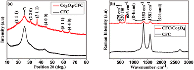
Fig. 1(a) shows the XRD pattern of the bare carbon fibre cloth and Co3O4 grown carbon fibre cloth Co3O4/CFC. The XRD peaks positioned at 18.9, 31.2, 36.6, 44.7, 59.4, and 65.1 and their relative intensities can be indexed to the planes of (111), (220), (311), (400), (422), (511) and (440) cubic spinel Co3O4.18 The broad diffraction peaks indicate the formation of nano-crystalline Co3O4 over CFC surface.Raman spectra of the pure CFC and Co3O4/CFC samples as shown in Fig. 1(b) further confirming the growth of Co3O4. The bare carbon cloth shows the strong Raman peaks at around 1353 cm−1 and 1581 cm−1 corresponding to the disordered D-band and graphitic G-band modes.37 After Co3O4 growth process followed by the calcinations, the new bands at 475, 520, and 686 cm−1 were observed and it can be assigned to the Eg, F2g1 and A1g modes of crystalline Co3O4 confirming the formation of Co3O4 nanostructures on CFC surface.49 These bands mainly arise by the tetrahedral and octahedral cations (Co2+/Co3+) lattice vibrations in the spinel structure.
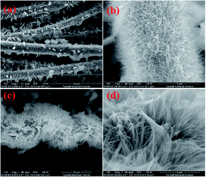
The Co3O4 grown CFC surface was examined with the high resolution scanning electron microscope (HRSEM) as illustrated in Fig. 2(a–d) indicating the growth of well-constructed free standing nanowire/nanoflower architecture. Fig. 2(a) shows the low magnification SEM images of bundles of carbon fibers which is covered by Co3O4 nanowires and nanoflowers. Densely packed nanowires grown on a single carbon fiber can be observed in Fig. 2(b). As can be seen from the high magnification SEM images of (c) and (d), the hierarchical nanoflower comprise of nanowires that assembled together to form flower like microstructure. The EDS spectrum captured at the selected portion of the nanoflowers as shown in Fig. S1 of the ESI† confirmed the presence of Co and O with the dominant carbon peak.
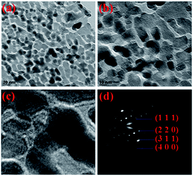
TEM images of Co3O4 nanowire/nanoflower hybrid structure are shown in Fig. 3(a–c) and Fig. S2(a–d).† From HRTEM images of Fig. 3(a–c), the formation of uniformly distributed ultra-fine nanocrystals with mesoscale range (3–8 nm) of pores was observed. From Fig. 3(c), the combined properties of porosity and the crystallinity of calcined Co3O4 nanowire/nanoflower hybrid nanostructure was confirmed. It was observed that the average crystallite sizes were in the range of 10–12 nm and uniformly distributed over the petals of the nanoflowers grown from nanowire bundles. Fig. 3(d) shows the selected area diffraction pattern with multi-spot-rings clearly represents the polycrystalline nature of Co3O4 nanostructure. Further, the rings can be indexed to the (111), (220), (311) and (440) planes of spinel Co3O4. The estimated d spacing value for the corresponding [hkl] plane of 311 was found to be ∼0.26 nm, which is in good agreement with the standard JCPDS file (#42-1467) as well as to the XRD analysis discussed earlier.
The detailed growth process of Co3O4 nanoflowers is schematically represented in Fig. S3 (ESI†). The formation of Co3O4 nanostructure may be described by the following chemical reactions (1)–(4):
| CO(NH2)2 + 3H2O → 2NH4OH + CO2↑ | (1) |
| 2NH4OH → 2NH4+ + 2OH− | (2) |
| Co2+ + 2OH− → Co(OH)2 | (3) |
| 3Co(OH)2 + 0.5O2 → Co3O4 + 3H2O | (4) |
The interesting nanoflower architecture growth mechanism was proposed as follows: herein urea played a crucial role to form the nanoflower architecture. Initially, the urea hydrolysis produced an excess amount of NH3·H2O, which increased the solution pH gradually to ∼9. Under hydrothermal process, the released NH3 and CO2 may exist in the form of bubbles which made the complex [Co2+·NH4] as well as acted as a soft templates for the growth of Co(OH)2 nanoparticles.50 At the initial stage, the NH4+ intercalated Co(OH)2 nanoparticles around CO2 bubbles and formed loosely packed nanowire aggregates. During nucleation the nanowires self-assembled together and formed the hierarchical nanoflower architecture after calcination at 300 °C by releasing the intercalated soft templates. However, the exact growth mechanism for this nanoflower is not clear yet and requires further investigations.
Typical N2 isotherm curve for the CFC/Co3O4 nanoflower shown in Fig. 4, designates the type IV hysteresis loop. With the increased relative pressure, an expanded hysteresis was observed in the range between 0.7 and 1, which demonstrated the mesoporous nature of the material. This Co3O4 nanoflower/CFC revealed a Brunauer–Emmett–Tellar (BET) surface area of ∼60.3 m2 g−1, which is comparable to the similar Co3O4 hierarchical nanostructures.18 The corresponding Barrett–Joyner–Halenda (BJH) pore size distribution curve is shown in the inset of Fig. 4, which further supports the mesoporous characteristic features of the Co3O4 nanoflowers. From the curve it can be observed that the largest number of pores is distributed at ∼4 nm with the highest pore volume and should be more favourable for rapid ion transport within the electrode surface.
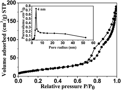 | ||
| Fig. 4 N2 adsorption and desorption curve of Co3O4 nanostructure and the corresponding pore size distribution (inset). | ||
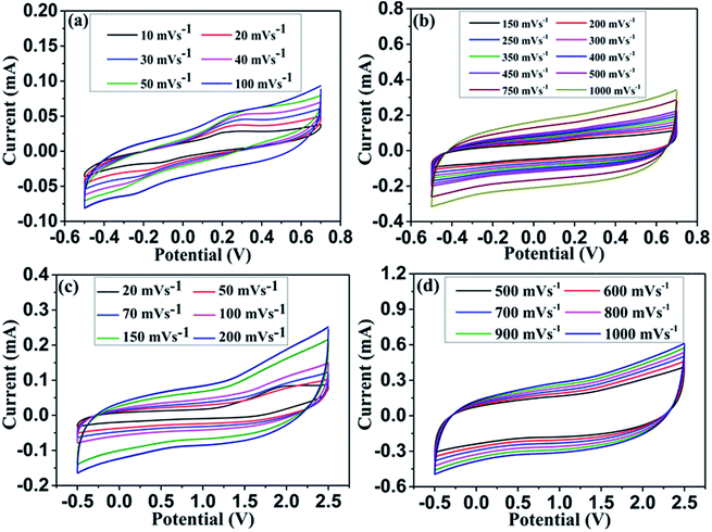 | ||
| Fig. 5 Cyclic voltammograms of Co3O4 based symmetric supercapacitor in 3 M KOH (a & b) and 1 M TEABF4 in PC (c & d) measured at different scan rates. | ||
A symmetric supercapacitor was fabricated using two Co3O4/CFC nanowire/nanoflower hybrid electrodes separated by celgard separator. The electrochemical activity of the symmetric capacitor was evaluated by cyclic voltammetry, charge–discharge cyclability and impedance analysis. Fig. 5(a–d) represents the scan rate dependent cyclic voltammograms of the symmetric supercapacitor in aqueous (a & b) and non-aqueous (c & d) electrolytes. The CV curves measured at the scan rate ranging from 10 to 100 mV s−1 showed in Fig. 5(a) indicates the pseudocapacitive features of the electrode in 3 M KOH over the potential window −0.5 to 0.7 V. At the lower scan rate of 10 mV s−1 there is a visible pair of redox peaks, which appears even at 100 mV s−1 implying the high rate charge transfer kinetics between Co2+/Co3+ redox couples in the Co3O4 electrode surface. At the higher scan rate, distinct rectangular CV curve was observed over the scan rate ranging from 150 mV s−1 to 1000 mV s−1 demonstrating ultra-high rate capability of the electrodes. Usually the rate capability of the metal oxide nanostructures in aqueous electrolyte is limited to 200 mV s−1.26,38 Surprisingly, our hybrid nanostructure have shown a superior rate capability of 1000 mV s−1, which was never been reported before for the metal oxide electrode. This may be attributed to the fast and efficient electron and ion transport in the electrode surface even at high rates. Interestingly, the CV curves exhibit well symmetry in both anodic and cathodic sweeps even at high scan rate of 1000 mV s−1 infer highly reversible redox reaction in the electrode surface. However, the slight deviation in CV curve measured at 1000 mV s−1 with delayed current reversals at the both ends ascribes the limited ion transport in the electrode surface. In order to understand the electrochemical performance in non-aqueous electrolyte, the two pieces of Co3O4/CFC electrodes sandwiched using celgard separator. 1 M TEABF4 in propylene carbonate (PC) was used as a non-aqueous electrolyte to evaluate the device performance. Fig. 5(c & d) shows the cyclic voltammograms of Co3O4 electrode in non-aqueous electrolyte measured at various scan rates ranging from 20 to 1000 mV s−1. Similar to the aqueous electrolyte, Co3O4 hybrid nanostructured electrode shows distinct CV response with respect to scan rate. Also, it showed the asymmetric features due to the influence of carbon fibre substrate. It was further confirmed with the CV and charge–discharge curves measured in 1 M TEABF4 using pure carbon cloth electrode. Fig. S4(a & b)† clearly shows the influence of carbon cloth substrate both in positive and negative region. Furthermore, the measured specific capacitance was very low for pristine CFC electrodes, which is only ∼0.1 mF cm−2. For Co3O4/CFC electrode, CV curve shows the combination of both capacitive and battery behaviours at very low scan rate of 20 mV s−1.42 When the scan rate increases, the featureless current response in the CV curves is observed, representing the dominant pseudocapacitive characteristic of the electrode at high scan rates. The high current response in both anodic and cathodic sweeps may be attributed to the redox reaction at electrode/electrolyte interfaces. Unlike the aqueous electrolyte, the electrode shows wider potential window of ∼2.5 V and highly reversible current in the organic electrolyte as shown in Fig. 5(d). Noteworthy, the Co3O4 hybrid nanostructured electrode exhibits an extreme rate capability in organic electrolyte system. The CV curve measured at ultra-fast scan rates ranging from 1500 to 12![[thin space (1/6-em)]](https://www.rsc.org/images/entities/char_2009.gif) 000 mV s−1 are represented in Fig. S5(a & b) (ESI†). A superior charge transfer kinetics in the electrode surface was observed even at extreme scan rate of 12
000 mV s−1 are represented in Fig. S5(a & b) (ESI†). A superior charge transfer kinetics in the electrode surface was observed even at extreme scan rate of 12![[thin space (1/6-em)]](https://www.rsc.org/images/entities/char_2009.gif) 000 mV s−1. The rate performance of the electrode in organic electrolyte is approximately 10 times higher compared to the aqueous electrolyte. Also, the highly reversible current response at ultra-fast scan rates demonstrates the high power performance of the electrode in organic electrolyte. To examine the rate capability of the electrode in both aqueous and non-aqueous electrolytes, the areal capacitances were calculated using the following eqn (5):
000 mV s−1. The rate performance of the electrode in organic electrolyte is approximately 10 times higher compared to the aqueous electrolyte. Also, the highly reversible current response at ultra-fast scan rates demonstrates the high power performance of the electrode in organic electrolyte. To examine the rate capability of the electrode in both aqueous and non-aqueous electrolytes, the areal capacitances were calculated using the following eqn (5):
 | (5) |
![[thin space (1/6-em)]](https://www.rsc.org/images/entities/char_2009.gif) 000 mV s−1, the corresponding areal capacitance further decreased to 0.37 mF cm−2 in organic electrolyte, which is 6% of the capacitance measured at the lowest scan rate of 20 mV s−1. This result demonstrates a comparable specific capacitance and far better rate capability of the electrode in organic electrolyte when compared to the inorganic electrolyte. It may be resulting from the well-integrated nanowire/nanoflower hybrid nanostructure of the electrode and better chemical compatibility of the CFC substrate with the organic electrolyte.
000 mV s−1, the corresponding areal capacitance further decreased to 0.37 mF cm−2 in organic electrolyte, which is 6% of the capacitance measured at the lowest scan rate of 20 mV s−1. This result demonstrates a comparable specific capacitance and far better rate capability of the electrode in organic electrolyte when compared to the inorganic electrolyte. It may be resulting from the well-integrated nanowire/nanoflower hybrid nanostructure of the electrode and better chemical compatibility of the CFC substrate with the organic electrolyte.
The superior electrochemical performance of the Co3O4 symmetric supercapacitor was further investigated with the galvanostatic charging–discharging measurements in both aqueous and non-aqueous electrolytes. Typical charge–discharge profiles observed at different current densities are shown in Fig. 6(a & b). Both the graphs showed nearly triangular shaped linear charge–discharge profile over the measured potential limit confirming the capacitive characteristics of the electrodes. In order to further interrogate the specific capacitance and rate capability of the electrode, the areal capacitance was estimated from discharge curve using the eqn (6):
| Ca = IΔt/AΔV | (6) |
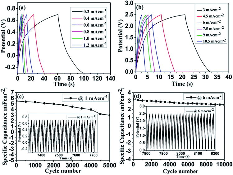 | ||
| Fig. 6 Charge–discharge profile of Co3O4/CFC based symmetric supercapacitor in 3 M KOH (a), 1 M TEABF4 (b) and their corresponding cyclic performance (c & d). | ||
The long term stability of the device was investigated by repeated charge–discharge cycles. Fig. 6(c & d) shows the cyclic performance of the symmetric supercapacitor tested in both aqueous and non-aqueous electrolytes. Insets of the Fig. 6(c & d) represents the repeated charge–discharge profiles at constant current density. In aqueous electrolyte, the continuous charge–discharge measurement carried out at a constant current density of 1 mA cm−2 and could preserve 54% of its initial capacitance at the end of 5000 cycles. The limited capacitance retention in aqueous electrolyte may be explained by an increased electrode resistance and destruction of the microstructure. It was further confirmed with the SEM images shown in Fig. S7(a–d) and S8(a–d) (ESI†) after stability test in aqueous and non-aqueous electrolytes, respectively. After cycling test, the detachment of nanowire/nanoflower microstructure was observed in both electrolytes, which reduced the overall efficiency of the device. From Fig. 6(d), it can be seen that cyclic stability of the device is greatly improved in the organic electrolyte, which showed 80% of capacitance retention after 10![[thin space (1/6-em)]](https://www.rsc.org/images/entities/char_2009.gif) 000 cycles. The enhanced cyclic stability in organic electrolyte confirms superior electrochemical activity of our Co3O4/CFC hybrid electrode. This may be due to features associated to the well-integrated hybrid microstructure and intrinsic characteristic of CFC including chemical compatibility and superior electrical conductivity.
000 cycles. The enhanced cyclic stability in organic electrolyte confirms superior electrochemical activity of our Co3O4/CFC hybrid electrode. This may be due to features associated to the well-integrated hybrid microstructure and intrinsic characteristic of CFC including chemical compatibility and superior electrical conductivity.
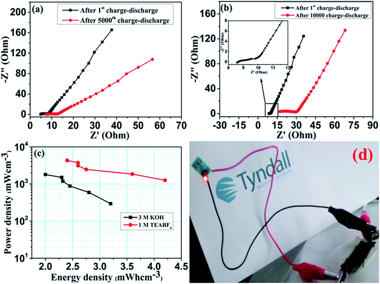
The electrochemical kinetics of Co3O4 symmetric supercapacitor was further exemplified by electrochemical impedance spectra (EIS). Nyquist plots of symmetric cell in both aqueous and non-aqueous electrolytes measured before and after cyclic test are shown in Fig. 7(a & b). Both the graphs have shown similar impedance spectra over the measured frequency range. The EIS spectra consist of visible semicircle in high frequency region and sloped straight line in low frequency portion.37,38 The observed semicircle is related to the charge transfer resistance (Rct), which contributes to the pseudocapacitance. Followed by the semicircle, the sloped line associates the ion diffusion within the electrode surface. Typically, the diameter of the semicircle at high frequency region provides charge transfer resistance of the electrode. The estimated Rct value is approximately 3.19 and 5.4 Ω for aqueous electrolyte and 1.7 and 11.45 Ω for non-aqueous electrolyte before and after the cycle test. Interestingly, both the devices have exhibited low charge transfer resistance even after the prolonged cycle test, which indicates the superior electrical conductivity of the hybrid electrode. This result is in consistent with both CV and charge–discharge measurements and demonstrate good electrochemical performance of the Co3O4 electrode in non-aqueous electrolyte.
The energy and power performance of the supercapacitor are the important factors for practical applications. Therefore the energy and power density of the Co3O4 symmetric supercapacitors have been evaluated for both aqueous and non-aqueous electrolytes using following equations:38
| E = CV2/2U | (7) |
| P = (E/t) | (8) |
In a view to practical application, we examined the mechanical flexibility of the symmetric supercapacitor in organic electrolyte system. The fabricated symmetric supercapacitor is light weight and moderately flexible. Fig. 8(a) shows the CV curve measured at 500 mV s−1 in repeated bend position of 60° (see the inset image). Under stressed position, the supercapacitor showed little disruption in the CV curve, which indicates limited flexibility of the device. Impedance analysis was carried out for repeated bending of the device, which is shown in Fig. 8(b). Nyquist plots clearly evidence the capacitive features of the device even at stressed condition. However repeated bending varies the charge transfer resistance as well as the solution resistance due to the mechanical deformation. Thereby, it can be concluded that the device can be used for limited stressed condition.
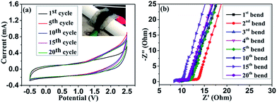 | ||
| Fig. 8 CV curves measured with bending position in organic electrolyte at 500 mV s−1 (a) and Nyquist plot for the device measured at repeated bending (b). | ||
The interesting electrochemical features of hydrothermally grown Co3O4 nanostructure/CFC electrode were possibly due to their desired structural benefits. In brief, the highly flexible and conducting carbon fibre cloth substrate provided the good mechanical integrity and adhesion between electroactive material and substrate during faradaic reaction. Consequently, the nanosheet like petals of nanoflowers offered the highly exposed surface for electrolyte contact, which significantly enhanced the core-level redox process. Furthermore, the ordered mesopore distribution with large pore volume leaded to more ion diffusion within the electrode. The direct contact between metal oxide and CFC further supported the good electrical conductivity. Over all from this investigation it can be inferred that the controlled growth of Co3O4 nanostructure on CFC with the desired 3D hierarchical flower like architecture can be used as a flexible electrode for supercapacitor. The electrode showed good chemical and mechanical feasibility in non-aqueous electrolyte system and thereby it can be used for high energy and power performance flexible supercapacitor.
Conclusions
In summary, we fabricated a hierarchical Co3O4 nanowire/nanoflower hybrid architecture by facile hydrothermal approach and demonstrated as superior electrode material for aqueous and non-aqueous electrolyte based symmetric supercapacitor. As a binder free electrode for supercapacitor, it showed a specific capacitance of 7.8 mF cm−2 and 4.8 mF cm−2 for 3 M KOH and 1 M TEABF4 respectively. When compared to aqueous electrolyte, the symmetric supercapacitor in non-aqueous electrolyte exhibits far better electrochemical reversibility towards long term applications. Interestingly, the Co3O4 nanowire/nanoflower hybrid nanostructure showed enhanced energy and power density in organic electrolyte with a moderate potential range of ∼2.5 V. Furthermore, the device possesses reasonable mechanical flexibility under bending conditions, which may lead to the potential fabrication of flexible energy storage device. The achieved electrochemical performance of the electrode mainly due to the advantages came through their desired 3D hierarchical hybrid architecture, high surface area, good electrical conductivity, and well integration of Co3O4 with CFC.Acknowledgements
The authors acknowledges the financial support from EU FP7 project MANpower (contract number: 604360) to carry out this work. The SEM images by Han Shao are gratefully acknowledged.References
- A. S. Arico, P. Bruce, B. Scrosati, J. M. Tarascon and W. Van Schalkwijk, Nat. Mater., 2005, 4, 366–377 CrossRef CAS PubMed.
- M. Winter and R. J. Brodd, Chem. Rev., 2004, 104, 4245–4269 CrossRef CAS PubMed.
- P. Simon and Y. Gogotsi, Nat. Mater., 2008, 7, 845–854 CrossRef CAS PubMed.
- J. R. Miller and P. Simon, Science, 2008, 321, 651–652 CrossRef CAS PubMed.
- X. Peng, L. Peng, C. Wu and Y. Xi, Chem. Soc. Rev., 2014, 43, 3303–3323 RSC.
- T. Chen and L. Dai, J. Mater. Chem. A, 2014, 2, 10756–10775 CAS.
- L. Yuan, X.-H. Lu, X. Xiao, T. Zhai, J. Dai, F. Zhang, B. Hu, X. Wang, L. Gong, J. Chen, C. Hu, Y. Tong, J. Zhou and Z. L. Wang, ACS Nano, 2012, 6, 656–661 CrossRef CAS PubMed.
- G. Wang, L. Zhang and J. Zhang, Chem. Soc. Rev., 2012, 41, 797–828 RSC.
- X. Zhao, B. M. Sanchez, P. J. Dobson and P. S. Grant, Nanoscale, 2011, 3, 839–855 RSC.
- E. G. Calvo, F. Lufrano, P. Staiti, A. Brigandi, A. Arenillas and J. A. Menéndez, J. Power Sources, 2013, 241, 776–782 CrossRef CAS.
- Y. Gao, G. P. Pandey, J. Turner, C. R. Westgate and B. Sammakia, Nanoscale Res. Lett., 2012, 7, 651 CrossRef PubMed.
- E. A. de Morais, G. Alvial, R. Longuinhos, J. M. A. Figueiredo, R. G. Lacerda, A. S. Ferlauto and L. O. Ladeira, Mater. Res., 2011, 14(3), 403–407 CrossRef CAS.
- H. Jin, X. Wang, Z. Gu, G. Anderson and K. Muthukumarappan, J. Environ. Chem. Eng., 2014, 2, 1404–1409 CrossRef CAS.
- W.-w. Liu, X.-b. Yan, J.-w. Lang, C. Peng and Q.-j. Xue, J. Mater. Chem., 2012, 22, 17245–17253 RSC.
- W.-w. Liu, X.-b. Yan, J.-w. Lang, Ji-b. Pu and Q.-j. Xue, New J. Chem., 2013, 37, 2186–2195 RSC.
- L. Y. Chen, J. L. Kang, Y. Hou, P. Liu, T. Fujita, A. Hirata and M. W. Chen, J. Mater. Chem. A, 2013, 1, 9202–9207 CAS.
- S. Cheng, L. Yang, Y. Liu, W. Lin, L. Huang, D. Chen, C. P. Wong and M. Liu, J. Mater. Chem. A, 2013, 1, 7709–7716 CAS.
- X.-h. Xia, J.-p. Tu, Y.-j. Mai, X.-l. Wang, C.-d. Gu and X.-b. Zhao, J. Mater. Chem., 2011, 21, 9319–9325 RSC.
- L. Huang, D. Chen, Y. Ding, S. Feng, Z. Lin Wang and M. Liu, Nano Lett., 2013, 13, 3135–3139 CrossRef CAS PubMed.
- Z. w. Xu, Z. Li, X. Tan, C. M. B. Holt, L. Zhang, B. S. Amirkhiz and D. Mitlin, RSC Adv., 2012, 2, 2753–2755 RSC.
- W. Chen, R. B. Rakhi and H. N. Alshareef, J. Mater. Chem. A, 2013, 1, 3315–3324 CAS.
- H. Zhang, Q. Zhao, S. Zhou, N. Liu, X. Wang, J. Li and F. Wang, J. Power Sources, 2011, 196, 10484–10489 CrossRef CAS.
- C. H. Wu, Q. Shen, R. Mi, Si X. Deng, Y. Q. Shu, H. Wang, J. B. Liu and H. Yan, J. Mater. Chem. A, 2014, 2, 15987–15994 CAS.
- K. Deori, S. K. Ujjain, R. K. Sharma and S. Deka, ACS Appl. Mater. Interfaces, 2013, 5, 10665–10672 CAS.
- W. Yang, Z. Gao, J. Ma, J. Wang, B. Wang and L. Liu, Electrochim. Acta, 2013, 112, 378–385 CrossRef CAS.
- L. Yang, S. Cheng, Y. Ding, X. Zhu, Z. L. Wang and M. Liu, Nano Lett., 2012, 12, 321–325 CrossRef CAS PubMed.
- J. Yan, T. Wei, W. Qiao, B. Shao, Q. Zhao, L. Zhang and Z. Fan, Electrochim. Acta, 2010, 55, 6973–6978 CrossRef CAS.
- M. Zhi, C. Xiang, J. Li, M. Li and N. Wu, Nanoscale, 2013, 5, 72–88 RSC.
- H. Yan, D. Zhang, J. Xu, Y. Lu, Y. Liu, K. Qiu, Y. Zhang and Y. Luo, Nanoscale Res. Lett., 2014, 9, 424 CrossRef PubMed.
- S.-L. Chou, J.-Z. Wang, H.-K. Liu and S.-X. Dou, J. Electrochem. Soc., 2008, 155, A926–A929 CrossRef CAS.
- H. A. Moreno, S. Hussain, R. Amade and E. Bertran, Mater. Res. Express, 2014, 1, 035050 CrossRef.
- S. K. Tripathi, A. Jain, A. Gupta and M. Kumari, Indian J. Pure Appl. Phys., 2013, 51, 315–319 CAS.
- L. Oakes, A. Westover, J. W. Mares, S. Chatterjee, W. R. Erwin, R. Bardhan, S. M. Weiss and C. L. Pint, Sci. Rep., 2013, 3, 3020 CrossRef PubMed.
- H. Wang and X. Wang, ACS Appl. Mater. Interfaces, 2013, 5, 6255–6260 CAS.
- S. Wang, B. Pei, X. Zhao and R. A. W. Dryfe, Nano Energy, 2013, 2, 530–536 CrossRef CAS.
- J. Zhao, J. Chen, S. Xu, M. Shao, D. Yan, M. Wei, D. G. Evans and X. Duan, J. Mater. Chem. A, 2013, 1, 8836–8843 CAS.
- N. Padmanathan and S. Selladurai, RSC Adv., 2014, 4, 8341–8349 RSC.
- Y. Qian, R. Liu, Q. Wang, J. Xu, D. Chen and G. Shen, J. Mater. Chem. A, 2014, 2, 10917–10922 CAS.
- Y.-C. Chen, Y.-K. Hsu, Y.-G. Lin, Y.-K. Lin, Y.-Y. Horng, L.-C. Chen and K.-H. Chen, Electrochim. Acta, 2011, 56, 7124–7130 CrossRef CAS.
- D. Guo, Y. Luo, X. Yu, Q. Lin and T. Wang, Nano Energy, 2014, 8, 174–182 CrossRef CAS.
- S. H. Kazemi, A. Asghari and M. A. kiani, Electrochim. Acta, 2014, 138, 9–14 CrossRef CAS.
- K.-W. Nam, C.-W. Lee, X.-Q. Yang, B. W. Cho, W.-S. Yoon and K.-B. Kim, J. Power Sources, 2009, 188, 323–331 CrossRef CAS.
- Sellam and S. A. Hashmi, ACS Appl. Mater. Interfaces, 2013, 5, 3875–3883 CAS.
- E. Coadou, L. Timperman, J. Jacquemin, H. Galiano, C. Hardacre and M. Anouti, J. Phys. Chem. C, 2013, 117, 10315–10325 CAS.
- S.-J. Park and K.-S. Kim, Microscopy: Science, Technology, Application and Education, 2010, vol. 3, pp. 1905–1916 Search PubMed.
- E. A. Miller, L. F. Rull, L. F. Vega and K. E. Gubbins, J. Phys. Chem., 1996, 100, 1189–1196 CrossRef.
- B. Rand and R. Robinson, Carbon, 1977, 15, 311–315 CrossRef CAS.
- J. A. Menendez, Thermochim. Acta, 1998, 312, 79–86 CrossRef CAS.
- T. Yu, Y. Zhu, X. Xu, Z. Shen, P. Chen, C.-T. Lim, J. T.-L. Thong and C.-H. Sow, Adv. Mater., 2005, 17, 1595–1599 CrossRef CAS.
- M. Roy, S. Ghosh and M. K. Naskar, Dalton Trans., 2014, 43, 10248–10257 RSC.
- C.-M. Yang, Y.-J. Kim, M. Endo, H. Kanoh, M. Yudasaka, S. Iijima and K. Kaneko, J. Am. Chem. Soc., 2007, 129, 20–21 CrossRef CAS PubMed.
- C. Masarapu, L.-P. Wang, X. Li and B. Wei, Adv. Energy Mater., 2012, 2, 546–552 CrossRef CAS.
- L. Wu, R. Li, J. Guo, C. Zhou, W. Zhang, C. Wang, Y. Huang, Y. Li and J. Liu, AIP Adv., 2013, 3, 082129 CrossRef.
Footnote |
| † Electronic supplementary information (ESI) available: Images of EDS spectrum, TEM images of nanowire/nanoflower hybrid structure, schematic representation of Co3O4 nanoflower growth, CV and charge–discharge graphs of CFC based supercapacitor, high scan rate CV graphs, scan rate and current density dependent specific capacitance graphs, SEM images of the electrodes after cycling tests, table showing energy and power performance of the symmetric capacitor in aqueous and non-aqueous electrolytes. See DOI: 10.1039/c4ra13327g |
| This journal is © The Royal Society of Chemistry 2015 |

