Flexible organic field-effect transistors on biodegradable cellulose paper with efficient reusable ion gel dielectrics

Chuan Qianab, Jia Sun*ab, Junliang Yangab and Yongli Gaoabc
aInstitute of Super-microstructure and Ultrafast Process in Advanced Materials (ISUPAM), School of Physics and Electronics, Central South University, Changsha, Hunan 410083, China. E-mail: jiasun@csu.edu.cn
bHunan Key Laboratory for Super-microstructure and Ultrafast Process, School of Physics and Electronics, Central South University, Changsha, Hunan 410083, China
cDepartment of Physics and Astronomy, University of Rochester, Rochester, NY 14627, USA

Received 27th October 2014 , Accepted 22nd January 2015

First published on 22nd January 2015


Abstract

Reusable and renewable electronics is an emerging field aimed at the development of environmentally safe, disposable and biocompatible devices. Here, we demonstrate the fabrication of flexible poly(3-hexylthiophene) (P3HT) field-effect transistors (FETs) on cellulose paper with biopolymer chitosan smoothing layers and efficient reusable ion gel gate dielectrics. The high specific capacitance of ion gels led to the formation of an electric-double-layer (EDL) at the channel/dielectric interface that plays a critical role in modulating the currents of the devices. Reasonable electrical characteristics and mechanical flexibility were observed. Transistors with an operating voltage as low as 2 V, a source drain current of up to ∼1 mA, a current on/off ratio of 3–4 orders of magnitude and a large field-effect mobility of ∼0.97 cm2 V−1 s−1 have been obtained. Especially, the laminated ion gels can be in situ peeled off and reused in other FETs and the device performance is not degenerated obviously with repeated use. The unique flexibility of the FETs on paper with reusable ion gel dielectrics manifests their applications as the next generation of throwaway electronics.

Introduction

Organic field-effect transistors (OFETs) built on low-cost flexible substrates are suitable for flexible electronics in wearable sensors, biomedical devices, smart cards, and other emerging applications, and are also potentially suitable for fast roll-to-roll printing processes.1–6 Up to the present, a large amount of research has focused on the pursuit of high-performance electronic devices using plastic as a more durable and lightweight substrate, without considering biocompatibility and reusability.7–9 It is known that plastic is made from the by-products of the oil industry and the biodegradation of plastic is very slow.10 With increasing growth of plastic electronics, solid plastic waste may increase dramatically.11 Because the substrate occupies a large part of a device, there are some initial reports addressing the use of cost-effective and environmentally friendly materials as substrates in organic electronics.12–16 The described development may eventually result in environmentally safe and disposable or throwaway electronic applications.17

By virtue of the abundance, renewable and biodegradable properties of cellulose, paper is an excellent alternative with exceptional technological attributes and commercial perspectives for many substrates available.18 Functional electronic components, including solar cells,19 sensors,20 biomedical devices,21 conductive circuits,22 and FET,23 have recently been produced on paper substrates. However, most of organic electronic devices usually require smooth interfaces, and the large surface roughness and porous structure of paper are intrinsic barriers to hosting electronic devices on this material.23 On the other hand, another crucial issue of the FETs based on paper is the operating voltage, which is of particular importance for distributed or single-use portable applications.24 To be compatible with paper devices, the gate dielectric should not only reproduce the advantageous properties of the paper, e.g., low-cost and flexibility, but should also be deposited near ambient conditions, yet processing a high gate capacitance. The gelation of ionic liquids with polymers is a promising approach for achieving high specific capacitance due to formation of electric-double-layer (EDL), widely used in fabricating flexible FETs.25–27 However, most of ionic liquids used to date are toxic in nature and far away from being “green” electronics.28 Thus, the reusability of ion gels is important for disposable paper devices. A kind of electrolyte-gated FET with in-plane-gate device structure was developed,29,30 which alleviate technical issues arising from complicated electrode alignment and top-gate electrode deposition and is very convenient for device fabrications.31,32

In this article, we report on the demonstration of flexible poly(3-hexylthiophene) (P3HT) FETs fabricated on biodegradable cellulose paper with an in-plane-gate device structure where biocompatible chitosan is used as the smoothening layer and laminated ion gel is used as high capacitance dielectrics. The fabricated FETs were measured in ambient conditions and showed a field-effect mobility of up to 0.97 cm2 V−1 s−1, a current on/off ratio of approach to 104, a narrow voltage range of 2 V, and a mechanical flexibility. Being a direct-lamination method, the ion gel dielectrics can be easily reused in other devices by in situ peeling the films off from FETs. The device performance of the cellulose-paper-based FETs with reused ion gel dielectrics is not degenerated obviously with the times of repeated use. These combined technologies for the fabrication of flexible OFETs on low-cost and environmental-friendly paper hold great promises for portable and disposable electronics.

Experimental

The fabrication of OFETs was carried out on commercially available printing papers. Due to high surface roughness of the unmodified papers, the biocompatible chitosan was used as smoothening layer. For the preparation of chitosan films, a chitosan solution (2% w/w) was first prepared by dissolving chitosan powder in aqueous acetic acid (2% v/v). The viscous solution was spin coated three times onto paper substrates followed by evaporating the solvent at 70 °C for 2 hours to form homogeneous solid films. Semiconducting P3HT (purchased from Sigma-Aldrich) was spin coated from dichlorobenzene (15 mg mL−1) on chitosan/paper substrate under air at 2000 rpm and cured at 50 °C for 2 hours. The source, drain, and in-plane-gate Au electrodes were then deposited through a shadow mask, defining a channel with a length of L = 80 μm and a width of W = 1600 μm. The ion gel dielectric layer was spin-coated on glass with an acetone solution of poly(vinylidene fluoride-co-hexafluoropropylene) (P(VDF-HFP)) (purchased from Sigma-Aldrich) and 1-ethyl-3-methylimidazolium bis(trifluoromethylsulfonyl)amide ([EMI][TSFA]) (purchased from TCI Chemicals). The weight ratio of P(VDF-HFP)[thin space (1/6-em)]:[thin space (1/6-em)][EMI][TSFA][thin space (1/6-em)]:[thin space (1/6-em)]acetone was 1[thin space (1/6-em)]:[thin space (1/6-em)]2:[thin space (1/6-em)]7 and 1[thin space (1/6-em)]:[thin space (1/6-em)]4:[thin space (1/6-em)]7. Spin coated ion gel films were placed in oven at 70 °C for 1 day to remove the residual solvent. The tailor-made ion gels were transferred and laminated onto the in-plane-gate OFETs, according to a previously reported method.31 For the reusability test, the ion gel dielectrics was peeled off from the FETs and transferred to another device using tweezers. For the capacitance measurement, the free-standing ion gels were sandwiched between Au electrodes with a metal–ion gel–metal (MIM) capacitor structure. The surface morphology of the paper and chitosan/paper was characterized by scanning electron microscopy (SEM, FEI HELIOS NanoLab 600i) and atomic force microscopy (AFM, Agilent Technologies). SEM samples were prepared by depositing a thin layer of Au onto the paper and chitosan/paper. The fabricated flexible OFETs on cellulose paper were electrically characterized under a dark condition in air using semiconductor parameter analyzer (Keithley 4200-SCS) and a probe station with a clean and shielded box in air ambient. Impedance measurements of ion gels were recorded for frequencies between 1 Hz to 0.1 MHz by electrochemical workstation with oscillation amplitude of 5 mV and dc-bias of 0 V.

Result and discussion

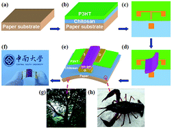
A schematic representation of the proposed device with an in-plane-gate configuration including all the fabrication steps as well as the different layers is detailed in Fig. 1(a)–(e). Here the gate is not deposited on the channel but located next to OFET on the substrate. The free-standing and tailor-made ion gel film is used as high-capacitance gate dielectric by film-transfer lamination process. Fig. 1(f) shows a photograph of the fabricated flexible OFETs on cellulose paper. Cellulose is the major biopolymer on the earth, which is extracted from trees by chemical processes and mechanical treatments and is the main building block of paper (Fig. 1(g)). Smoothing of the paper is efficiently achieved by biopolymer chitosan with a simple fabrication route. Chitosan is obtained from deacetylation of chitin which is derived from the exoskeleton of crustaceans and insects (Fig. 1(h)) and is the second most abundant biopolymer in nature next to cellulose.33 Unlike plastics, these natural biopolymers are low cost and biodegradable and will not contribute to “white pollution”.
image file: c4ra13240h-f1.tif
Fig. 1 (a)–(e) A schematic diagram of the fabrication processes of the OFETs on cellulose paper. (f) A photograph of the fabricated flexible OFETs on cellulose paper. (g) and (h) The natural materials for the preparation of paper and chitosan.

The microstructures and morphologies of each layer in an OFET impact its electrical properties and hence affect the device's performance. SEM was performed on the cellulose paper with and without chitosan coating, as shown in Fig. 2(a) and (b). In general, the surface of the bare paper is remarkable roughness, with micron-size pores and defects being observed, as seen in Fig. 2(a). Previous studies suggest that a smooth surface is necessary for high performance OFETs mainly due to the formation of high-quality semiconducting films with fewer defect states.34 The relatively smooth morphology shown in Fig. 2(b) suggests that the bare paper was well covered by the chitosan layer after the spin-coating of chitosan. The inset of Fig. 2(b) shows the fracture cross-sectional SEM image of the chitosan coated onto bare paper. Because of the large surface roughness and porosity of the paper, the chitosan was somewhat penetrated into the substrate and the boundary between the chitosan and bare paper is not clear. Fig. 3 shows the AFM morphology and height image (scan area: 1 μm × 1 μm) of the paper substrates with various coating layers. As expected from the observation through SEM, the surface characteristic of the bare paper substrate shown in Fig. 3(a) is very poor. From the line scan of the surface height image, the maximum roughness depth of 25 nm and root mean square roughness (RMS) of 11.3 nm is observed in bare paper. Its rough surface requires the addition of a smooth layer. The AFM image of chitosan coated paper substrate is displayed in Fig. 3(b). Compared to the bare paper, the surface of chitosan is relatively smooth with the RMS of 2.01 nm and the surface height is less than 5 nm. Therefore, the RMS roughness has been considerably reduced after the coating of chitosan. To investigate the microstructure of the P3HT on chitosan/paper, we examined an AFM morphology image of the film. As shown in Fig. 3(c), the P3HT surface is composed of homogeneously distributed nanoaggregates. The height variation and the RMS roughness (2.45 nm) of the spin-coated P3HT film are comparable to the chitosan/paper.


image file: c4ra13240h-f2.tif
Fig. 2 (a) The SEM image of the surface morphology of bare paper. (b) The SEM image of the surface morphology of after chitosan deposition. Inset: the fracture cross-sectional SEM image of the chitosan coated onto bare paper.

image file: c4ra13240h-f3.tif
Fig. 3 AFM morphologies and height images of (a) bare paper substrate, (b) chitosan coated onto bare paper and (c) P3HT and chitosan coated onto bare paper.

We examined the capacitive behavior of the ion gels through impedance spectroscopy measurements on MIM capacitor test structure. The device structure is illustrated in Fig. 4(a). The effective electrode area that was in contact with the electrolyte is about 0.17 cm2. The relationship between capacitance and frequency can be extracted from the electrochemical impedance spectroscopy. Fig. 4(b) shows the specific capacitance as a function of frequency in the range between 1 Hz and 0.1 MHz. The specific gate capacitance is as high as 33 μF cm−2 at 1 Hz. The obtained capacitance value is about 3 orders of magnitude larger than that of a thermal grown 100 nm-thick SiO2 dielectric. The large capacitance of the ion gels is attributed to the polarization of the ionic liquid and the formation of EDLs at the ion gel/Au interfaces. Especially, the specific capacitance is still above 1 μF cm−2 at 10 kHz, which indicates that the ions within the gel are high mobile and can form EDL quickly. The formation of EDLs can provide a strong capacitive coupling effect, which can effectively tune the conductance of channel at very low voltage range.


image file: c4ra13240h-f4.tif
Fig. 4 (a) The MIM capacitor test structure for impedance spectroscopy measurements. (b) Frequency dependence of the specific capacitance of the ion gels.

The electrical characteristics of the OFETs with laminated ion gels (P(VDF-HFP)[thin space (1/6-em)]:[thin space (1/6-em)][EMI][TSFA] = 1[thin space (1/6-em)]:[thin space (1/6-em)]4) on paper substrates are presented in Fig. 5. The device shows the expected gate modulation of drain current (Ids) in both the linear and saturation regimes, as shown Fig. 5(a). Owing to high gating efficiency of ion gels as a gate dielectric, high-current output and low-voltage operation can be achieved by the formation of the EDL on the channel of OFETs. Notably, large saturation currents Ids of ∼1 mA is obtained at low gate voltage (Vg) of −2 V and drain voltage (Vds) of −1 V. From the transfer characteristic curve, it can be seen that the OFETs performs as a typical p-channel device with an on/off ratio approach to 104. We have measured tens of FETs and the current on/off ratio is range from 103 to 104. The threshold voltage (Vth) of the device is calculated to be 0.67 V. The subthreshold slope (S), which is defined as the gate voltage that is necessary to alter the Ids by one order of magnitude, is found to be 270 mV per decade. Fig. 5(b) shows the output characteristic curve of the device with Vg varied between 2 V to −2 V and the Vds swept from 0 to −1 V. This curve reveals quite decent current saturation at high Vds and an excellent linear behavior at low Vds indicating good ohmic contacts formed at HT/Au interfaces. The transistor transfer curve in the linear regime and the leakage current IgVg curve are shown in Fig. 5(c) and (d), which were obtained at the same sweep rate of ∼0.2 V s−1. Because of the high ionic conductance of ion gels, the gate leakage currents of these devices are within a range of 10−7 to 10−6 A and changed with the sweep rate.


image file: c4ra13240h-f5.tif
Fig. 5 (a) Transfer characteristic curves (Ids vs. Vg) of an OFET on paper with Vds = −1 V. (b) Output characteristic curves (Ids vs. Vds) of an OFET on paper at different Vg values. (c) The transistor transfer curve in the linear regime with Vds = −0.1 V and (d) the leakage current IgVg curve of an OFET on paper.

For the ion gel gated devices, it is necessary to understand the doping mode in the transistor channel. The primary distinction between the electrostatic and electrochemical doping is whether the ions from ion gels mange to penetrate the semiconductor.35 In order to distinguish the doping model of the ion gels gated FETs, X-ray photoemission spectroscopy (XPS) was used to analyze the composition change of the P3HT channel on Si/SiO2 substrate before and after ion gel gating. First, the gate voltage (Vg) of the device was swept from 2 V to −2 V, and then the ion gel was peeled off from the FETs after gating. The sample was washed by deionized water to remove the physical adsorbed ionic liquids. Fig. 6(a) shows the chemical structures of the P3HT and ionic liquid ([EMI][TFSA]). The black and red curves of the Fig. 6(b) are the XPS scans of the as prepared P3HT films and after ion gel gating, respectively. Both survey scans present the S, O and C spectra, which exhibit S2p, S2s, C1s and O1s peaks at around 164 eV, 228 eV, 284 eV and 532 eV. The presents of the O peak is possibly due to the incorporation of oxygen and water molecules in the P3HT layer, which is consistent with the previously published results.36,37 It can be clearly observed from Fig. 6(c) and (d) (both are enlarged spectra) that the F1s (688 eV) and N1s (398 eV) peaks are raised in the P3HT film after ion gel gating, which can be attributed to the [TFSA] from the ionic liquid penetrate into the semiconductor. Some research groups have also demonstrated the ions doping of the electrolyte-gated FETs.35,38 Therefore, the operating mechanism of our devices is electrochemical doping.


image file: c4ra13240h-f6.tif
Fig. 6 (a) The chemical structures of the P3HT and ionic liquid ([EMI][TFSA]). (b) The XPS scans of the as prepared P3HT films (black) and after ion gel gating (red). (c) and (d) The enlarged F1s and N1s peaks of P3HT film.

In order to obtain the mobility, the gate capacitance of the ion gels was required. However, the effective capacitance of the ion gel depends on the applied gate voltage and the nature of the interface and penetration of ions into the semiconductor. Hence, the specific capacitance obtained by impedance spectroscopy can not be used for the mobility calculation. According to the previous methods,39,40 the hole mobility in the linear regime was obtained from:

image file: c4ra13240h-t1.tif
where e is the elementary charge and p is the injected carrier density, deduced from:
image file: c4ra13240h-t2.tif
where Ig is the gate current (as shown in Fig. 5(d)), rv is the sweep rate (rv ∼0.2 V s−1) and A is the channel area of the FETs. Using this method, the mobility is calculated to be 0.97 cm2 V−1 s−1, which is significantly higher than that from conventional SiO2-gated device but close to the carrier mobility measured in electrolyte gated P3HT FETs on flat substrates.41–43

To demonstrate the flexibility of the FETs on paper, the devices were bended with a bending radius of 17 mm (along the channel transport axis) and the electrical characterization was carried out in air during bending. Fig. 7 shows the transfer curves of the FETs without bending, with outward bending and after the outward bending and then inward bending of the substrate. Under outward bending stress the performance of the FETs degrades somewhat. The Ids (Vg = −2 V and Vds = −1 V) is decrease from 2.1 mA to 0.68 mA. After the outward bending and then inward bending of the FETs, the Ids is slightly changed. In general, outward bending induces tensile strain to a device, which can alter the Ids of the FETs.44 The off-current and the leakage current through the ion gels remain the same. In addition, the bending induced any changes or damage to ion gels was not observed. These results suggest that the lamination of ion gels is suitable for the fabrication of flexible FETs. We have also compared the device performance of the ion gel gated P3HT in ambient and in vaccum. Compared with the device measured in air ambient, the device performance (data not shown) of the FETs measured in vaccum is greatly improved. It indicates that the oxygen and water absorption on the device would influence its electrical properties and degrade the electrical performance. Thus further work on device encapsulation should be done for practical applications.


image file: c4ra13240h-f7.tif
Fig. 7 Transfer characteristic curves of an OFET on paper without bending, with outward bending and after the outward bending and then inward bending of the substrate.

Because of the solubility of ionic liquids in water and toxicity of ionic liquids to aquatic organisms, the reusability of the ion gels should be considered for the environmental friendly electronic applications.28 Efficient reuse of the ion gel gated OFET on cellulose paper is presented in Fig. 8(a). The major advantage of the film-transfer lamination procedure is that the ion gels can be delaminated by in situ peeling the films off from OFETs and easy to be reused in other device. Fig. 8(b) and (c) shows the current on/off ratio and Vth values of four OFETs on paper substrates gated by reused ion gels with different concentrations. The black lines indicate average values. All of these devices can be switched between “on” and “off” by the reused ion gels. The current on/off ratio and Vth values of all the devices gated with the reused ion gels is not degenerated obviously with the times of repeated use, which indicates that the ion gels peeled off by tweezers can be reused in OFETs. After peeling off ion gels, the paper based devices can be discarded with daily paper waste. We also performed burning test of the paper based devices after the delamination of ion gels. Paper based OFETs can be burned out by fire within several seconds. The main residua are Au and ash and the reuse of Au can be performed by recovery technologies for the secondary supply of Au.45 A small content of sulfur in P3HT may have slight negative impact on our environment, future works will be focused on the development of truly “green” electronics by using biocompatible semiconductors, such as, ZnO, biodegradable organic materials and carbon-based semiconductors.


image file: c4ra13240h-f8.tif
Fig. 8 (a) A schematic diagram of the efficient reuse of the ion gel dielectrics. (b) and (c) The current on/off ratio and Vth values of four OFETs on paper substrates gated by reused ion gels with different concentrations.

Conclusions

In summary, we demonstrated the fabrication of flexible OFETs on biodegradable paper substrates with efficient reusable ion gel dielectrics. A biopolymer chitosan was used as the smoothing layer and a free-standing ion gel laminated on in-plane-gate OFETs was used as gate medium. The OFETs on paper substrates showed excellent operating characteristics with a low operating voltage of 2 V, a high field-effect mobility of ∼0.97 cm2 V−1 s−1, a current on/off ratio of 104, and a subthreshold swing of 270 mV per decade. Owing to the unique device structure and the simple device fabrication procedure, the ion gels were efficient reused in other OFETs without obvious device performance degeneration. These results make a step towards environmentally safe devices in low-cost, reusable or throwaway electronic applications. While further optimization will be required to transform biocompatible semiconductor materials for use in truly “green” electronics.

Acknowledgements

This project was supported in part by the National Natural Science Foundation of China (61306085, 11334014, 51173205), the China Postdoctoral Science Foundation (2013M530357), the Hunan Postdoctoral Scientific Program (2013RS4045), and The Postdoctoral Science Foundation of Central South University. J. Yang acknowledges support from the National Natural Science Foundation of China (51203192) and the Hunan Provincial Natural Science Foundation of China (13JJ4019). Y. Gao acknowledges the support from National Science Foundation DMR-1303742.

References

  1. K. Fukuda, Y. Takeda, Y. Yoshimura, R. Shiwaku, L. T. Tran, T. Sekine, M. Mizukami, D. Kumaki and S. Tokito, Nat. Commun., 2014, 5, 4147 Search PubMed.
  2. A. Campana, T. Crammer, D. T. Simon, M. Berggren and F. Biscarini, Adv. Mater., 2014, 26, 3874 CrossRef CAS PubMed.
  3. S. C. B. Mannsfeld, B. C. Tee, R. M. Stoltenberg, C. V. H. Chen, S. Barman, B. V. O. Muir, A. N. Sokolov, C. Reese and Z. Bao, Nat. Mater., 2010, 9, 859 CrossRef CAS PubMed.
  4. D. Khodagholy, V. F. Curto, K. J. Fraser, M. Gurfinkel, R. Byrne, D. Diamond, G. G. Malliaras, F. Benito-Lopez and R. M. Owens, J. Mater. Chem., 2012, 22, 4440 RSC.
  5. B. Tian, T. Cohen-Karni, Q. Qing, X. Duan, P. Xie and C. M. Lieber, Science, 2010, 329, 830 CrossRef CAS PubMed.
  6. P. H. Lau, K. Takei, C. Wang, Y. Ju, J. Kim, Z. Yu, T. Takahashi, G. Cho and A. Javey, Nano Lett., 2013, 13, 3864 CrossRef CAS PubMed.
  7. H. E. A. Huitema, G. H. Gelinck, J. B. P. H. van der Putten, K. E. Kuijk, C. M. Hart, E. Cantatore, P. T. Herwig, A. J. J. M. van Breemen and D. M. de Leeuw, Nature, 2001, 414, 599 CrossRef CAS PubMed.
  8. Y. G. Seol, H. Y. Noh, S. S. Lee, J. H. Ahn and N.-E. Lee, Appl. Phys. Lett., 2008, 93, 013305 CrossRef PubMed.
  9. C.-F. Sung, D. Kekuda, L. F. Chu, Y.-Z. Lee, F.-C. Chen, M.-C. Wu and C.-W. Chu, Adv. Mater., 2009, 21, 1–5 CrossRef PubMed.
  10. H. Zhu, Z. Xiao, D. Liu, Y. Li, N. J. Weadock, Z. Fang, J. Huang and L. Hu, Energy Environ. Sci., 2013, 6, 2105 CAS.
  11. M. Irimia-Vladu, Chem. Soc. Rev., 2014, 43, 588 RSC.
  12. D. Tobjörk and R. Österbacka, Adv. Mater., 2011, 23, 1935 CrossRef PubMed.
  13. M. Irimia-Vladu, E. D. Głowacki, G. Schwabegger, L. Leonat, H. Z. Akpinar, H. Sitter, S. Bauer and N. S. Sariciftci, Green Chem., 2013, 15, 1473 RSC.
  14. D.-H. Kim, Y.-S. Kim, J. Wu, Z. Liu, J. Song, H.-S. Kim, Y. Y. Huang, K.-C. Hwang and J. A. Roger, Adv. Mater., 2009, 21, 3703 CrossRef CAS.
  15. M. Irimia-Vladu, P. A. Troshin, M. Reisinger, L. Shmygleva, Y. Kanbur, G. Schwabegger, M. Bodea, R. Schwödiauer, A. Mumyatov, J. W. Fergus, V. F. Razumov, H. Sitter, N. S. Sariciftci and S. Bauer, Adv. Funct. Mater., 2010, 20, 4069 CrossRef CAS.
  16. C. J. Bettinger and Z. Bao, Adv. Mater., 2010, 22, 651 CrossRef CAS PubMed.
  17. M. Irimia-Vladu, N. S. Sariciftci and S. Bauer, J. Mater. Chem., 2011, 21, 1350 RSC.
  18. W. J. Hyun, O. O. Park and B. D. Chin, Adv. Mater., 2013, 25, 4729 CrossRef CAS PubMed.
  19. Z. Fang, H. Zhu, Y. Yuan, D. Ha, S. Zhu, C. Preston, Q. Chen, Y. Li, X. Han, S. Lee, G. Chen, T. Li, J. Munday, J. Huang and L. Hu, Nano Lett., 2014, 14, 765 CrossRef CAS PubMed.
  20. K. A. Mirica, J. G. Weis, J. M. Schnorr, B. Esser and T. M. Swager, Angew. Chem., Int. Ed., 2012, 51, 10740 CrossRef CAS PubMed.
  21. M. N. Costa, B. Veigas, J. M. Jacob, D. S. Santos, J. Gomes, P. V. Baptista, R. Martins, J. Inácio and E. Fortunato, Nanotechnology, 2014, 25, 094006 CrossRef CAS PubMed.
  22. M.-C. Hsieh, C. Kim, M. Nogi and K. Suganuma, Nanoscale, 2013, 5, 9289 RSC.
  23. N. Kurra, D. Dutta and G. U. Kulkarni, Phys. Chem. Chem. Phys., 2013, 15, 8367 RSC.
  24. Q. Sun, D. H. Kim, S. S. Park, N. Y. Lee, Y. Zhang, J. H. Lee, K. Cho and J. H. Cho, Adv. Mater., 2014, 26, 4735 CrossRef CAS PubMed.
  25. J. H. Cho, J. Lee, Y. Xia, B. Kim, Y. He, M. J. Renn, T. P. Lodge and C. D. Frisbie, Nat. Mater., 2008, 7, 900 CrossRef CAS PubMed.
  26. J. Pu, Y. Yomogida, K.-K. Liu, L.-J. Li, Y. Iwasa and T. Takenobu, Nano Lett., 2012, 12, 4013 CrossRef CAS PubMed.
  27. F. Xu, M.-Y. Wu, N. S. Safron, S. S. Roy, R. M. Jacobberger, D. J. Bindl, J.-H. Seo, T.-H. Chang, Z. Ma and M. S. Arnold, Nano Lett., 2014, 14, 682 CrossRef CAS PubMed.
  28. T. P. T. Pham, C.-W. Cho and Y.-S. Sun, Water Res., 2010, 44, 352 CrossRef CAS PubMed.
  29. J. Jiang, J. Sun, W. Dou, B. Zhou and Q. Wan, Appl. Phys. Lett., 2011, 98, 113507 CrossRef PubMed.
  30. S. Dasgupta, R. Kruk, N. Mechau and H. Hahn, ACS Nano, 2011, 5, 9628 CrossRef CAS PubMed.
  31. K. H. Lee, M. S. Kang, S. Zhang, Y. Gu, T. P. Lodge and C. D. Frisbie, Adv. Mater., 2012, 24, 4457 CrossRef CAS PubMed.
  32. S. Thiemann, S. J. Sachnov, F. Pettersson, R. Bollström, R. Österbacka, P. Wasserscheid and J. Zaumseil, Adv. Funct. Mater., 2014, 24, 625 CrossRef CAS.
  33. W. Suginta, P. Khunkaewla and A. Schulte, Chem. Rev., 2013, 113, 5458 CrossRef CAS PubMed.
  34. J. Huang, H. Zhu, Y. Chen, C. Preston, K. Rohrbach, J. Cumings and L. Hu, ACS Nano, 2013, 7, 2106 CrossRef CAS PubMed.
  35. J. Lee, L. G. Kaake, J. H. Cho, X.-Y. Zhu, T. P. Timothy and C. D. Frisbie, J. Phys. Chem. C, 2009, 113, 8972 CAS.
  36. C.-H. Chang, M.-F. Chen and C.-H. Chien, J. Electrochem. Soc., 2011, 158, H854 CrossRef CAS PubMed.
  37. D. Chi, S. Qu, Z. Wang and J. Wang, J. Mater. Chem. C, 2014, 2, 4383 RSC.
  38. L. G. Kaake, Y. Zou, M. J. Panzer, C. D. Frisbie and X.-Y. Zhu, J. Am. Chem. Soc., 2007, 129, 7824 CrossRef CAS PubMed.
  39. B. D. Paulsen and C. D. Frisbie, J. Phys. Chem. C, 2012, 116, 3132 CAS.
  40. J. Sayago, F. Soavi, Y. Sivalinggam, F. Cicoira and C. Santato, J. Mater. Chem. C, 2014, 2, 5690 RSC.
  41. Z. Bao, A. Dodabalapur and A. J. Lovinger, Appl. Phys. Lett., 1996, 69, 4108 CrossRef CAS PubMed.
  42. W. Shi, J. Ye, J. G. Checkelsky, C. Terakura and Y. Iwasa, Adv. Funct. Mater., 2014, 24, 2005 CrossRef CAS.
  43. J. H. Cho, J. Lee, Y. He, B. Kim, T. P. Lodge and C. D. Firsbie, Adv. Mater., 2008, 20, 686 CrossRef CAS.
  44. Y. Fujisaki, H. Koga, Y. Nakajima, M. Nakata, H. Tsuji, T. Yamamoto, T. Kurita, M. Nogi and N. Shimidzu, Adv. Mater., 2014, 24, 1657 CAS.
  45. C. Hagelüken and C. W. Corti, Gold Bull., 2010, 43, 209 CrossRef.

This journal is © The Royal Society of Chemistry 2015