Covalent triazine-based framework as an efficient catalyst support for ammonia decomposition

Fei Changab, Jianping Guoab, Guotao Wua, Lin Liua, Miao Zhangab, Teng Hea, Peikun Wangab, Pei Yuab and Ping Chen*ac
aDalian National Laboratory for Clean Energy, Dalian Institute of Chemical Physics, Chinese Academy of Sciences, Dalian-116023, P. R. China
bUniversity of Chinese Academy of Sciences, Beijing-100049, P. R. China
cState Key Laboratory of Catalysis, Dalian Institute of Chemical Physics, Chinese Academy of Sciences, Dalian-116023, P. R. China. E-mail: pchen@dicp.ac.cn; Fax: +86-411-8437-9583

Received 21st October 2014 , Accepted 2nd December 2014

First published on 5th December 2014


Abstract

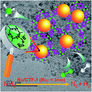
The covalent triazine-based framework (CTF), a new type of nitrogen-containing microporous polymer, was employed as a catalyst support for ammonia decomposition. Either in terms of NH3 conversion rate or turnover frequency, Ru/CTF-1 has a highly enhanced performance compared to Ru/CNTs, which rank as one of the best un-promoted catalysts reported so far. The compositional and structural information of Ru/CTF-1 and Ru/CNTs catalysts have been characterized by ICP, N2 physisorption, XRD, TEM, XPS, and NH3-TPD techniques. Ru particles on CTF-1 and CNTs are ca. 3 nm in diameter and have a similar degree of dispersion. However, the binding energy of Ru 3p electrons is ca. 0.6 eV less for Ru/CTF-1 than that for Ru/CNTs showing significant increase in electron density in the former, which is likely due to the interaction between the nitrogen-rich groups of CTF-1 and the Ru nanoparticles. Moreover, the presence of CTF-1 enhances the chemisorption of NH3, which, together with the increased electron density of Ru, may facilitate the competitive chemisorption of NH3 and recombinative desorption of adsorbed nitrogen via lowered activation energy and thus, enable faster reaction rate.


1. Introduction

There is increasing interest in employing ammonia as an energy carrier.1 Ammonia decomposition to COx-free hydrogen, an ideal fuel for PEM (proton exchange membrane) fuel cells,2,3 can be effectively catalyzed by the group VIII transition metals, among which the supported ruthenium catalysts have the highest activity.4,5 Au et al. investigated the effects of a number of supports and demonstrated the overall performance is in the order of CNTs > MgO > TiO2 ≈ AC ≈ Al2O3.6 Similar results were also reported by Zhu et al.7 Multi-walled Carbon Nanotubes (MWCNTs) have a surface area greater than 100 m2 g−1 and have relatively good graphitic degree.8 However, there are electron-withdrawing groups (–COOH, –OH) on the surface of CNTs, which may affect the electronic structure of Ru.9–12 By using Morse potential method, Bell et al. demonstrated that the rate limiting step for ammonia decomposition on Ru surface is the recombinative desorption of adsorbed nitrogen atoms,13 which can be promoted by the electropositive elements such as alkalis.7 On the other hand, increasing the charge density of CNTs or CNFs (Carbon Nanofibers) by doping surface nitrogen groups also leads to a significantly improved activity in ammonia decomposition.14–16 As nitrogen atoms can serve as strong anchoring points for the metal and behave as electron donors, the superior catalytic behaviors of nitrogen-containing carbon materials have been identified in different catalytic reactions.17–20

Covalent triazine-based frameworks (CTFs), representing a new type of nitrogen-containing microporous polymers, were first synthesized by Thomas et al. through the reversible ionothermal trimerization of aromatic nitriles in molten ZnCl2.21 CTFs have relatively high chemical and thermal stabilities due to the covalently bonded structure. Previous work indicates that CTFs are more stable than N-doped CNTs under hydrophilic and hydrophobic conditions.22 More importantly, CTFs possess some interesting properties such as large surface area, basicity and high degree of graphitization which make them attractive candidates for gas capture/storage and catalysis.23–30 As the content of nitrogen functional groups in CTFs overweighs that of N-doped CNTs, Pd supported on CTFs has a higher activity and stability in the alcohol oxidation reaction than on N-doped CNTs.22 Due to the plenty of nitrogen base sites, CTFs have been used as an efficient metal-free base catalyst directly to synthesize organic carbonates.26 By a simple combination of CTFs and Pt precursor, a highly active solid catalyst for methane selective oxidation has also been demonstrated.25

Previous reports on using CTFs as support are mainly for oxidative reaction. Herein, we investigate the performance of CTF-1, a crystalline triazine-based organic framework with hexagonal packing of pores,21 in a reductive process, i.e., ammonia decomposition. The catalytic activity of Ru/CTF-1 was measured and compared with the benchmark Ru/CNTs. Our results show that, either in terms of NH3 conversion rate or turnover frequency, the performance of Ru/CTF-1 is significantly superior to that of Ru/CNTs under the same conditions. The electron density of the Ru on CTF-1 is greater than that on CNTs, which facilitates the recombinative desorption of adsorbed nitrogen atoms. The stronger NH3 adsorption energy on Ru/CTF-1 surface may enhance the interaction of reactant with the ruthenium active sites and improve the ammonia decomposition activity.

2. Experimental

Catalyst preparation

CTF was prepared according to the procedure reported in literature.21 2,6-Dicyanopyridine (DCP) and ZnCl2 in a molar ratio of 1/5 were ball milled at 60 rpm for 0.5 h. Then the mixture was transferred into an ampoule under Ar atmosphere. The ampoule was sealed, evacuated and heated at 673 K for 40 h. After cooling down to room temperature, the ampoule was opened and the reaction mixture was grounded and washed with diluted HCl solution and water for several times to remove ZnCl2. Finally the black powder product was dried in Ar flow at 573 K for 3 h.

CNTs were pre-treated in aqueous HNO3 solution and calcined in an Ar flow at 573 K for 3 h.

Ru/CTF-1 and Ru/CNTs catalysts were prepared by traditional wetness incipient impregnation with RuCl3 as precursor and acetone as solvent. After drying in air for 12 h, catalysts were calcined in an Ar flow at 573 K for 3 h.

Catalytic test

The catalytic activity was evaluated on a continuous flow quartz reactor. Catalyst sample of 30 mg was placed in the central section of the reactor and was tested under a flow of pure NH3 (gas flow rate = 30 mL min−1, 15 mL min−1, 10 mL min−1) or a flow of diluted NH3 (5 vol% NH3/Ar, gas flow rate = 30 mL min−1). Prior to the measurement, Ru/CTF-1 and Ru/CNTs catalysts were reduced in pure NH3 at 673 K for 2 h and 773 K for 3 h, respectively. The effluent gasses were analyzed by a gas chromatograph equipped with a thermal conductivity detector (TCD) and a Porapak Q column, using hydrogen as the carrier gas.

Catalyst characterization

The actual Ru loadings of the catalysts were determined by inductively coupled plasma spectrometry (ICP-OES, optima 7300DV, Perkin-Elmer, USA).

X-ray diffraction (XRD) patterns were recorded on a PANalytical X'pert diffractometer with monochromatized Cu-Kα radiation (λ = 0.154 nm) at a setting of 40 kV and 40 mA.

Transmission electron microscope (TEM) images of the samples were taken on a JEM-2100 at 200 kV.

The specific surface area was measured on Autosorb-1 system (Quantachrome, USA) by N2 adsorption isotherm through BET method.

The X-ray photoelectron spectroscopy (XPS) measurement was performed using an Escalab 250 Xi X-ray photoelectron spectrometer (Thermo Scientific) with nonmonochromatic AlKα radiation (photon energy, 1486.6 eV). Small amount of Argon was injected into the sample by a weak sputtering under a very low ion current prior to the measurement. The binding energies were calibrated with reference to the Ar 2p (242.0 eV).

The temperature programmed desorption of ammonia (NH3-TPD) measurement was carried out on a home-made system combining a quartz reactor and a mass spectrometer to record the signal of NH3. The catalyst samples were reduced at 673 K in pure H2 for 2 h, and then the gas flow was switched to Ar for purging at 773 K for 2 h. After that the samples were cooled down to room temperature, where NH3 adsorption was performed. Physically adsorbed NH3 was removed by Ar at 373 K for 1 h. Then the temperature programmed desorption was carried out by heating the samples from 373 K to 723 K at a rate of 5 K min−1.

3. Results and discussion

Ru/CTF-1 and Ru/CNTs catalysts with different Ru loadings were prepared by traditional wetness incipient impregnation using RuCl3 as precursor and acetone as solvent, where the actual Ru loading was measured by ICP-OES (Table 1). The XRD characterizations of the Ru/CTF-1 catalyst samples only show the sheetlike structure of CTF-1 with (100) and (001) diffractions at ca. 7.0° and 25.1° respectively (Fig. 1d–f),21 evidencing the high dispersion of Ru on CTF-1, probably resulting from the strong metal–support interaction. The 2 wt% and 1 wt% Ru/CNTs catalysts also show no diffraction related to ruthenium metal. The diffraction peaks at 26.5°and 42.5° are attributed to CNTs (Fig. 1a–c), respectively, consistent with the results reported by Au et al.6
Table 1 Properties and activities of CTF-1 and CNTs supported Ru catalysts
Catalyst Ru loadinga [%] SBETb [m2 g−1] Particle sizec [nm] Dispersiond [%] TOFe [s−1] Eaf [kJ mol−1]
a Ru actual loading was determined by ICP-OES.b Specific surface area was determined by N2 physisorption, using BET method.c Statistical results of TEM images.d Dispersion was calculated employing spherical model proposed by Anderson.31e TOF values were measured under 5 vol% NH3/Ar flow at 673 K.f Activation energy was measured under pure NH3 flow at 623–723 K.
1 wt% Ru/CTF-1 0.82 654.6 2.9 45.5 0.58 69.1
2 wt% Ru/CTF-1 1.81 614.1 3.0 44.0 0.40 67.1
1 wt% Ru/CNTs 0.76 80.3 3.2 41.2 0.19 88.5
2 wt% Ru/CNTs 1.95 67.6 3.2 41.2 0.21 87.3


image file: c4ra12816h-f1.tif
Fig. 1 XRD patterns of (a) CNTs; (b) 1 wt% Ru/CNTs; (c) 2 wt% Ru/CNTs; (d) CTF-1; (e) 1 wt% Ru/CTF-1 and (f) 2 wt% Ru/CTF-1.

Transmission electron microscope (TEM) observation together with statistical analyses by counting 100 particles show that the particle size distributions of Ru supported on CTF-1 and CNTs are similar, between 1 nm and 5 nm (Fig. 2, insets), and the average Ru particle size of Ru/CTF-1 catalysts is slightly smaller than that of Ru/CNTs catalysts, but all of them are around 3 nm (Table 1) showing that Ru can be well dispersed on CTF-1 as well as on CNT. Because of the micropore size of CTF-1 is about 1.5 nm, which is smaller than the average Ru particle size, we believe the majority of Ru particles are located outside the micropores. However, the largely shrunken surface area of Ru/CTF-1 (see Table 1) compared with the pristine CTF-1 (SBET = 734.7 m2 g−1) indicates the blockage of the channels by Ru particles, anchoring at the openings of the CTF-1 channels. For the Ru/CNTs catalysts, Ru particles are essentially located on the external surface of CNTs. The degree of dispersion was calculated according to the spherical model proposed by Anderson (see Table 1),31 which shows that the dispersions of Ru in 1 wt% Ru/CNTs and 2 wt% Ru/CNTs catalysts are ca. 41.2%. With various functional groups (such as –COOH, –OH) bonded to the surface, CNTs can effectively anchor and disperse Ru nanoparticles.7 Dispersions of the 1 wt% Ru/CTF-1 and 2 wt% Ru/CTF-1 catalysts are 44.5% and 44.0% respectively, which are slightly higher than those of the Ru/CNTs catalysts. Chan-Thaw et al. reported that Pd NPs (nanoparticles) can be fixed on CTF-1 through the interaction with its nitrogen groups.22 Here we also attribute the high dispersion of Ru on CTF-1 to such a metal–support interaction.


image file: c4ra12816h-f2.tif
Fig. 2 TEM images of Ru-based catalysts. (a) 1 wt% Ru/CTF-1; (b) 2 wt% Ru/CTF-1; (c) 1 wt% Ru/CNTs and (d) 2 wt% Ru/CNTs. Insets: Ru particle size distributions.

N atoms in CTF-1 are essentially in sp2 hybridization. Their lone electron pairs are effective Lewis bases which can affect the electronic structure of Ru attached to them. As can be seen in Fig. 3, the electron binding energy of Ru 3p3/2 of pre-reduced 2 wt% Ru/CNTs is at ca. 461.6 eV, evidencing the metallic state of Ru in the catalyst. The electron binding energy of Ru 3p3/2 in 2 wt% Ru/CTF-1 is, interestingly, 0.6 eV smaller than that in 2 wt% Ru/CNTs. In other words, the electron density of Ru on CTF-1 is greater than that on CNTs.


image file: c4ra12816h-f3.tif
Fig. 3 XPS spectra of the ruthenium 3p3/2 region of (a) 2 wt% Ru/CTF-1; (b) 2 wt% Ru/CNTs.

The chemisorption of NH3 on catalysts was investigated by temperature-programmed desorption (TPD) technique. Fig. 4 shows the TPD profiles of the supported Ru catalysts and the supports themselves upon absorbing NH3 at ambient temperature followed by pre-heat treatment at 373 K. For neat CNTs and CTF-1 supports, little NH3 can be detected during the testing history. However, for CNTs and CTF-1 supported Ru catalysts, NH3 desorption can be observed in the temperature range of 400–500 K and 400–650 K, respectively. The NH3 desorption peak temperature of Ru/CTF-1 is at ca. 503 K, which is about 55 K higher than that of Ru/CNTs revealing stronger interaction between NH3 and Ru/CTF-1. Such a stronger chemisorption may facilitate the competitive chemisorption of NH3 molecules onto the active sites leading to an increased chance of reaction. Furthermore, the amount of desorbed NH3 from Ru/CTF-1 is obviously more than that of Ru/CNTs, which indicates more suitable sites for the strong adsorption of NH3 on the surface of Ru/CTF-1.


image file: c4ra12816h-f4.tif
Fig. 4 NH3-TPD profiles of (a) CNTs; (b) CTF-1; (c) 2 wt% Ru/CNTs and (d) 2 wt% Ru/CTF-1.

To minimize the effect of heat and mass transport during the endothermic ammonia decomposition reaction, a diluted ammonia (5 vol% NH3/Ar) flow was used as the reactant to uncover the intrinsic activities of the CTF-1 and CNTs supported Ru catalysts. Fig. 5a illustrates the NH3 conversion as a function of reaction temperature. The NH3 conversion of 2 wt% Ru/CNTs and 1 wt% Ru/CNTs is negligible at temperatures below 623 K. However, much higher conversion rates were observed on the CTF-1 supported catalysts. At 623 K, NH3 conversion rates over 1 wt% and 2 wt% Ru/CTF-1 is ca. 8.0 and 3.3 times higher than those of 1 wt% and 2 wt% Ru/CNTs, respectively. In higher temperature range, the catalytic activities of Ru/CTF-1 catalysts keep on overweighing those of the Ru/CNTs catalysts. It should be noted that the 1 wt% Ru/CTF-1 catalyst is even superior to 2 wt% Ru/CNTs under the same reaction condition. The turnover frequency (TOF) values (see Table 1) calculated from the hydrogen formation rate (mol gcat−1 s−1) per surface exposed Ru atom number per gram catalyst (mol gcat−1) show that at 673 K, the TOF over 2 wt% Ru/CTF-1 is ca. 2.0 times higher than that over 2 wt% Ru/CNTs. For the 1 wt% Ru based catalysts, it is 3.1 times.


image file: c4ra12816h-f5.tif
Fig. 5 Ammonia decomposition reaction activity test with 2 wt% Ru/CTF-1 (■); 2 wt% Ru/CNTs (○); 1 wt% Ru/CTF-1 (▲) and 1 wt% Ru/CNTs (▽). (a) Reaction conditions: catalyst (30 mg), 5 vol% NH3/Ar (flow rate = 30 mL min−1); (b) reaction conditions: catalyst (30 mg), pure NH3 (for 2 wt% Ru/CTF-1 and 2 wt% Ru/CNTs, flow rate = 15 mL min−1, GHSV = 30[thin space (1/6-em)]000 mL h−1 gcat−1; for 1 wt% Ru/CTF-1 and 1 wt% Ru/CNTs, flow rate = 10 mL min−1, GHSV = 20[thin space (1/6-em)]000 mL h−1 gcat−1).

Under a flow of pure NH3, the ammonia conversion rates over the Ru/CTF-1 are 1.5–2.5 times higher than those over Ru/CNTs in the temperature range of 598–723 K (see Fig. 5b). The turnover frequency values as a function of reaction temperature are shown in Fig. 6. Ruthenium loading has little influence upon TOF for the same kind of catalysts. The apparent activation energy of Ru/CTF-1 obtained from the Arrhenius plots is about 20 kJ mol−1 lower than that of Ru/CNTs (Fig. 7).


image file: c4ra12816h-f6.tif
Fig. 6 Turnover frequency of 1 wt% Ru/CNTs (▽); 1 wt% Ru/CTF-1 (●); 2 wt% Ru/CNTs (△) and 2 wt% Ru/CTF-1 (■) under pure NH3 flow at 598–723 K.

image file: c4ra12816h-f7.tif
Fig. 7 Arrhenius plots of 1 wt% Ru/CNTs (▽); 1 wt% Ru/CTF-1 (▲); 2 wt% Ru/CNTs (●) and 2 wt% Ru/CTF-1 (□). The temperature range (648–723 K) used for the determination of apparent activation energies was based on NH3 conversion values far away from the equilibrium values. The calculated average values and deviation errors of the Arrhenius plots were listed.

For Ru based catalysts, the B5 sites (five member sites on the steps of Ru (0001) plane) are regarded generally as the active sites for ammonia synthesis and decomposition.32,33 The amounts of B5 sites are structural sensitive and depend significantly on the size and dispersion of Ru particles. Previous investigations by Kowalczyk et al. showed that the maximum concentration of B5 sites was achieved when the Ru particle size is in the range of 1.8–2.5 nm.34 In our work, the Ru particle sizes of Ru/CTF-1 and Ru/CNTs catalysts are near the optimal range. Considering the similar Ru particle sizes and dispersions of all the CTF-1 and CNTs supported catalysts, the differences in activity (NH3 conversion rate and TOF) may not be ascribed to the particle size effect.

Bell et al. demonstrated that the rate limiting step of ammonia decomposition over Ru catalysts at relatively lower temperature is the recombinative desorption of adsorbed nitrogen atoms.13 At higher temperatures, the cleavage of N–H bond will be the rate-limiting step as proposed by Tsai and Weinberg.35 Bradford et al. suggested that both cleavage of N–H bond and recombinative desorption of adsorbed nitrogen atoms are kinetically slow on well-dispersed Ru.36 Support or additive which can facilitate electron feedback to the anti-bonding orbital of the transient metal–nitrogen bond should be beneficial for these steps.2 Compared with activated carbon, MgO, Al2O3 and TiO2, CNTs is the best support for ammonia decomposition because of its high metal dispersion and good degree of graphitization, which is beneficial for the electron transfer between support and Ru.11 Such an electron transfer process can be enhanced upon using CTF-1 as support due to the fact that the surface of CTF-1 is rich in nitrogen groups, leading to the increase in electron donation to Ru, which is evidenced by the downshift of binding energy of Ru 3p electrons. The increase in electron density on Ru surface, as discussed above, may lead to the decrease in the kinetic barrier for the recombinative removal of surface nitrogen atoms, which is also in accordance with the decrease in Ea measurements (i.e., Ea of Ru/CTF-1 is ca. 20 kJ mol−1 lower than that of Ru/CNTs).

NH3 and H2 have reaction orders of 0.69 and −1.6, respectively, over well dispersed Ru at 663 K.36 The negative reaction order for H2 shows its inhibition to ammonia decomposition, which can be attributed to the hindrance of surface sites by the strongly chemisorbed hydrogen.37 Our NH3-TPD profiles show that NH3 adsorption energy on Ru/CTF-1 is stronger than that on Ru/CNTs, which may, to a certain extent, enhance the chance of NH3 to interact with the ruthenium active sites and facilitate the activation of N–H bond, thus further improve the ammonia decomposition activity.

4. Conclusions

CTF-1, a kind of novel nitrogen-containing microporous polymer, is a superior support for Ru catalyst. The Ru/CTF-1 shows much better performance in ammonia decomposition than Ru/CNTs, which ranks one of the best un-promoted catalyst reported so far. Besides the high dispersion of Ru nanoparticles over CTF-1, we ascribe the improved performance to the rich nitrogen groups on CTF-1, which can anchor Ru nanoparticles and transfer electrons to Ru. The enhanced electron density of Ru surface is beneficial for the recombinative desorption of adsorbed nitrogen atoms. Nitrogen groups on CTF-1 play an important role as an electron donor to Ru and improve the catalytic activity.

Acknowledgements

The authors would like to acknowledge the financial supports from Project of National Natural Science Funds for Distinguished Young Scholars (51225206), 973 Project (2010CB631304) and the National Natural Science foundation of China (21133004 and 21273187).

References

  1. A. Klerke, C. H. Christensen, J. K. Norskov and T. Vegge, J. Mater. Chem., 2008, 18, 2304–2310 RSC.
  2. F. Hayashi, Y. Toda, Y. Kanie, M. Kitano, Y. Inoue, T. Yokoyama, M. Hara and H. Hosono, Chem. Sci., 2013, 4, 3124–3130 RSC.
  3. E. Garcia-Bordeje, S. Armenise and L. Roldan, Catal. Rev.: Sci. Eng., 2014, 56, 220–237 CAS.
  4. F. Schuth, R. Palkovits, R. Schlogl and D. S. Su, Energy Environ. Sci., 2012, 5, 6278–6289 Search PubMed.
  5. X. Z. Duan, X. G. Zhou and D. Chen, Catalysis, 2013, 25, 118–140 CAS.
  6. S. F. Yin, B. Q. Xu, W. X. Zhu, C. F. Ng, X. P. Zhou and C. T. Au, Catal. Today, 2004, 93–5, 27–38 CrossRef PubMed.
  7. L. Li, Z. H. Zhu, Z. F. Yan, G. Q. Lu and L. Rintoul, Appl. Catal., A, 2007, 320, 166–172 CrossRef CAS PubMed.
  8. P. Serp, M. Corrias and P. Kalck, Appl. Catal., A, 2003, 253, 337–358 CrossRef CAS.
  9. Z. H. Zhong and K. Aika, J. Catal., 1998, 173, 535–539 CrossRef CAS.
  10. Z. H. Zhong and K. Aika, Inorg. Chim. Acta, 1998, 280, 183–188 CrossRef CAS.
  11. S. F. Yin, B. Q. Xu, X. P. Zhou and C. T. Au, Appl. Catal., A, 2004, 277, 1–9 CrossRef CAS PubMed.
  12. K. Aika, A. Ohya, A. Ozaki, Y. Inoue and I. Yasumori, J. Catal., 1985, 92, 305–311 CrossRef CAS.
  13. E. Shustorovich and A. T. Bell, Surf. Sci., 1991, 259, L791–L796 CrossRef CAS.
  14. S. Armenise, L. Roldan, Y. Marco, A. Monzon and E. Garcia-Bordeje, J. Phys. Chem. C, 2012, 116, 26385–26395 CAS.
  15. J. L. Chen, Z. H. Zhu, S. B. Wang, Q. Ma, V. Rudolph and G. Q. Lu, Chem. Eng. J., 2010, 156, 404–410 CrossRef CAS PubMed.
  16. F. R. Garcia-Garcia, J. Alvarez-Rodriguez, I. Rodriguez-Ramos and A. Guerrero-Ruiz, Carbon, 2010, 48, 267–276 CrossRef CAS PubMed.
  17. R. Czerw, M. Terrones, J. C. Charlier, X. Blase, B. Foley, R. Kamalakaran, N. Grobert, H. Terrones, D. Tekleab, P. M. Ajayan, W. Blau, M. Ruhle and D. L. Carroll, Nano Lett., 2001, 1, 457–460 CrossRef CAS.
  18. K. P. Gong, F. Du, Z. H. Xia, M. Durstock and L. M. Dai, Science, 2009, 323, 760–764 CrossRef CAS PubMed.
  19. C. H. Hsu, H. M. Wu and P. L. Kuo, Chem. Commun., 2010, 46, 7628–7630 RSC.
  20. M. P. Woods, E. J. Biddinger, P. H. Matter, B. Mirkelamoglu and U. S. Ozkan, Catal. Lett., 2010, 136, 1–8 CrossRef CAS.
  21. P. Kuhn, M. Antonietti and A. Thomas, Angew. Chem., Int. Ed., 2008, 47, 3450–3453 CrossRef CAS PubMed.
  22. C. E. Chan-Thaw, A. Villa, L. Prati and A. Thomas, Chem.–Eur. J., 2011, 17, 1052–1057 CrossRef CAS PubMed.
  23. C. E. Chan-Thaw, A. Villa, G. M. Veith, K. Kailasam, L. A. Adamczyk, R. R. Unocic, L. Prati and A. Thomas, Chem.–Asian J., 2012, 7, 387–393 CrossRef CAS PubMed.
  24. X. M. Liu, H. Li, Y. W. Zhang, B. Xu, A. Sigen, H. Xia and Y. Mu, Polym. Chem., 2013, 4, 2445–2448 RSC.
  25. R. Palkovits, M. Antonietti, P. Kuhn, A. Thomas and F. Schuth, Angew. Chem., Int. Ed., 2009, 48, 6909–6912 CrossRef CAS PubMed.
  26. J. Roeser, K. Kailasam and A. Thomas, ChemSusChem, 2012, 5, 1793–1799 CrossRef CAS PubMed.
  27. X. W. Chen, F. Yuan, Q. F. Gu and X. B. Yu, J. Mater. Chem. A, 2013, 1, 11705–11710 CAS.
  28. J. L. Liu, E. M. Zong, H. Y. Fu, S. R. Zheng, Z. Y. Xu and D. Q. Zhu, J. Colloid Interface Sci., 2012, 372, 99–107 CrossRef CAS PubMed.
  29. A. Modak, J. Mondal, M. Sasidharan and A. Bhaumik, Green Chem., 2011, 13, 1317–1331 RSC.
  30. A. Thomas, A. Fischer, F. Goettmann, M. Antonietti, J. O. Muller, R. Schlogl and J. M. Carlsson, J. Mater. Chem., 2008, 18, 4893–4908 RSC.
  31. J. R. Anderson, Structure of metallic catalysts, Academic Press, New York, 1975 Search PubMed.
  32. C. J. H. Jacobsen, S. Dahl, P. L. Hansen, E. Tornqvist, L. Jensen, H. Topsoe, D. V. Prip, P. B. Moenshaug and I. Chorkendorff, J. Mol. Catal. A: Chem., 2000, 163, 19–26 CrossRef CAS.
  33. S. Dahl, J. Sehested, C. J. H. Jacobsen, E. Tornqvist and I. Chorkendorff, J. Catal., 2000, 192, 391–399 CrossRef CAS.
  34. W. Rarog-Pilecka, E. Miskiewicz, D. Szmigiel and Z. Kowalczyk, J. Catal., 2005, 231, 11–19 CrossRef CAS PubMed.
  35. W. Tsai and W. H. Weinberg, J. Phys. Chem. C, 1987, 91, 5302–5307 CrossRef CAS.
  36. M. C. J. Bradford, P. E. Fanning and M. A. Vannice, J. Catal., 1997, 172, 479–484 CrossRef CAS.
  37. W. Tsai, J. J. Vajo and W. H. Weinberg, J. Phys. Chem. C, 1985, 89, 4926–4932 CrossRef CAS.

This journal is © The Royal Society of Chemistry 2015
Click here to see how this site uses Cookies. View our privacy policy here.