
Three dimensional metal oxides–graphene composites and their applications in lithium ion batteries
Jiantao Zai
and
Xuefeng Qian
*
Shanghai Electrochemical Energy Devices Research Center, School of Chemistry and Chemical Engineering and State Key Laboratory of Metal Matrix Composites, Shanghai Jiao Tong University, Shanghai, 200240, P. R. China. E-mail: xfqian@sjtu.edu.cn; Fax: +86-21-54741297; Tel: +86-21-54743262
First published on 16th December 2014
Abstract
Because of the huge energy and environmental problems caused by the use of fossil fuels, R&D on innovative energy storage systems has never become so important as today. Although there are still some safety, energy, power and cost issues because of which electric vehicles are becoming more and more common in our daily life, such as E-bikes or E-cars. This paper provides an overview of the recent progress on three dimensional (3D) metal oxides–graphene (MOs–G) composites as advanced electrode materials in lithium ion batteries (LIBs). Beginning with a brief description of the importance and preparation methods of 3D MOs–G composites, the effects of the morphology and size of metal oxides (MOs) or graphene on composites for LIBs are then systematically reviewed and discussed. Additionally, important effects of composition and interactions between metal oxides and graphene are also pointed out. Finally, the future challenges of MOs–G composites for lithium ion batteries are discussed.
 Jiantao Zai | Dr Jiantao Zai received his Bachelor (2007) and Ph.D. (2012) degrees in Applied Chemistry from Shanghai Jiao Tong University, and then worked with Prof. Donghai Wang in Penn State University. He joined SJTU as a Lecturer in 2014. His research interests include the synthetic chemistry of Group IV inorganic materials and their potential applications in energy storage, photovoltaic and photocatalytic areas. He is honored to receive the 2014 Shanghai Chenguang project, 2012 Shanghai outstanding graduates and 2012 Scholarship of Sinopoly Battery Ltd. |
 Xuefeng Qian | Prof. Xuefeng Qian worked in the School of Chemistry and Chemical Engineering, Shanghai Jiao Tong University. He received his Bachelor degree from HeFei University of Technology (1990), Master (1995) and Ph.D (1998) degrees from USTC. He is interested in the design, synthesis, and applications of materials related with solar utilizations and energy storage. He was awarded the 2008 Outstanding University Young Teachers in Shanghai, 2006 New Century Excellent Talents of Education Ministry of China. |
1 Introduction
Reports from the Chinese Academy of Social Sciences indicate that there are more than 130 million vehicles in China in 2013, and the number is expected to be 400 million (one car per family) in the future.1 These vehicles have lead to massive traffic jams and are considered as one of the main reasons of the poor air quality in China. It is hard to image our future life if all of the increasing 270 million vehicles are based on fossil fuels. These problems are not only in China but also throughout the world. It is of no doubt that the development of electric vehicles (EVs) is one of the good choices. EVs have become more and more common in our daily life, for instance, E-bikes are widely used in both the city and countryside in China. However, the popularization of EVs is always limited by the safety, cost, cruising ability and power. To overcome these issues, people have started to expect better electrochemical performances from lithium ion batteries (LIBs).2–8 However, the development of better safety, higher energies and power densities in LIBs is meeting some technical bottlenecks at the present stage.Graphene is a two-dimensional (2D) sheet of sp2 bonded carbon atoms in a hexagonal honeycomb lattice, which can be viewed as an extra-large polycyclic aromatic molecule. Graphene nanosheets (GNSs) have been known to be composed of traditional carbon materials (e.g. graphite) or components of a “new” class of carbon materials (such as carbon nanotubes). The discovery of monolayer graphene can be tracked to the 1960s and 1970s.9 Then, graphene with the size of only tens of nm on an appropriate substrate (crystal surfaces of transition metals and metal carbides) was successfully fabricated by Oshima and Nagashima in 1997 through decomposing hydrocarbon gases at high temperature.10 Ruoff, R. S. also did pioneer works on tailoring graphite with the goal of achieving single sheets.11 After being first transferred to a SiO2 substrate by Geim and Novoselov in 2004, the field effect of graphene was demonstrated.10–12 The ideal GNSs achieved by a mechanical exfoliation technique have proven to be highly ordered, and have outstanding surface areas (2630 m2 g−1), high Young's modulus (1 TPa), high thermal conductivity (5000 W mK−1), strong chemical durability and high electron mobility (2.5 × 105 cm2 V−1 s−1).13–15
Since the chemical exfoliation method was developed to produce graphene at a low cost and in large quantities,16 graphene has been widely applied in polymer composites,17 transistors,18,19 optoelectronics,20,21 memory devices,22,23 sensors (gas-,24,25 bio-,26 electrochemical-27 and chemical-28), solar cells,20,29 field emission devices,30,31 catalysts,31 photocatalysts,14,32 nanogenerators,33 hydrogen storage34 and CO2 capture.35 Especially graphene-based electrochemical storage devices (e.g. high-performance LIBs) have attracted considerable attention in fundamental studies and practical applications with greatly improved electrochemical performances due to its unique 2D structure and excellent physiochemical properties.3,4,36–44 Furthermore, graphene-based electrochemical storage energy devices do not need high quality graphene without any defects, such as electronics, and graphene produced by the chemical exfoliation method, such as reduced graphite oxide (RGO) with many defects and multiple layers, can also meet the demands of high-performance LIBs.
Detailed descriptions of the properties, synthesis, functionalization and applications in energy storage areas of graphene and its composites can be found in recent papers.3–5,17,29,36,38–52 For example, Wu et al. systematically reviewed the pros and cons of graphene and metal oxides, and focused on the synergistic effects of metal oxides-graphene composites on improving the electrochemical properties of LIBs and electrochemical capacitors.49 Here, we provide an overview of the recent progress in three-dimensional (3D) metal oxides–graphene (MOs–G) composites as advanced lithium storage materials for high-performance LIBs since 2012, especially focusing on the important effects of morphologies, composition, interactions between metal oxides (MOs) and graphene on the improvement of their electrochemical properties, including capacity, rate capability and cyclic stability.
2 3D metal oxides–graphene composites
2.1 Why use 3D MOs–G composites
Due to its special 2D structure, graphene has a high Li+ ion storage capacity, 1116 mA h g−1 based on the LiC2 model53 or 744 mA h g−1 based on the Li2C6 model.54 However, graphene based electrodes usually show poor stability for the restacking of graphenes.37 Moreover, MOs with high theoretical reversible capacities (such as 717 mA h g−1 of NiO, 1007 mA h g−1 of Fe2O3, 755 mA h g−1 of MnO, 890 mA h g−1 of Co3O4) will suffer from huge volume changes during the continuous charge/discharge processes, which would lead to the rapid disintegration of anodes and capacity fading upon cycling. Furthermore, the lower electronic conductivity of MOs is another disadvantage. These problems can be greatly overcome by combining MOs with graphene to form composites with multiple synergistic effects. Wu et al.49 summarized these synergistic effects as following: (i) graphene is a novel 2D support for the uniform nucleating, growth or assembling of MOs with a well-defined size, shape and crystallinity; (ii) MOs between the layers of graphene can efficiently suppress the re-stacking of graphene; (iii) graphene can act as a 2D conductive template for building a 3D interconnected conductive porous network to improve the electrical conductivity and charge transport of pure oxides; (iv) graphene can suppress the volume change and particle agglomeration of MOs during the charge–discharge process; (v) oxygen-containing functional groups on graphene ensure good interfacial interactions and electrical contact between graphene and MOs.3D hierarchical structures in micro or sub-micro sizes, assembled by simple low dimensional nano-sized building blocks, can avoid the aggregation of anode materials and are beneficial for the electrode fabrication process.55–58 3D hierarchical structures can also provide more sites to connect with a conductive matrix (such as graphene, conductors or current collectors) and maintain the activity of Li storage materials during cycling. In addition, 3D hierarchical structures have additional benefits to greatly improve the electrochemical performance of electrode materials in LIBs, and they also show other special effects:56–58 the opening porous structures in 3D-hierarchical structures are readily accessible for an electrolyte, facilitating the transportation of Li+ ions from a liquid to the active surface of active materials. Second, nanosized building blocks of 3D hierarchical structures can significantly shorten the diffusion distance of Li+ ions, and therefore significantly enhance the lithium insertion–extraction kinetics. Third, 3D hierarchical structures with plenty of pores can accelerate phase transitions and restrain the crumbling and cracking of electrodes, leading to a superior cycling performance. In addition, well-connected 3D hierarchical structures with a large surface area can reduce the concentration polarization and facilitate electron transportation, which accounts for the high rate performance.
To date, several structural models of MOs–G composites have been developed, such as anchored, wrapped, encapsulated, sandwich-like, layered and mixed models (Fig. 1).49 Because of the large surface area and restacking nature of graphene, most graphene composites are in 3D hierarchical structures. These 3D MOs–G composites can combine the synergistic effects of graphene composites and benefits derived from 3D hierarchical structures together. Thus, they would possess better long-term stability and rate capability than pure 3D hierarchical MOs and graphene composites with simple structure, such as anchored model or sandwich-like model.
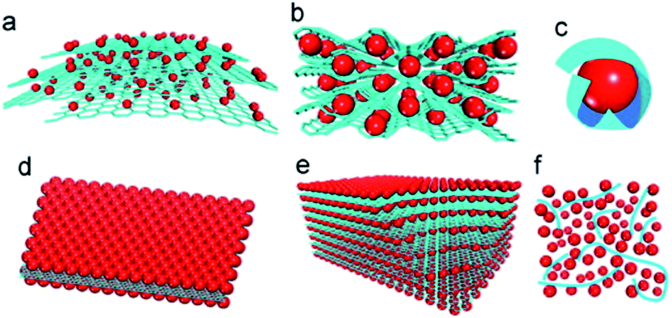 | ||
| Fig. 1 Schematic of structural models of MOs–G composites: (a) anchored model: nanosized MOs particles are anchored on the surface of graphene. (b) Wrapped model: MOs particles are wrapped by graphene. (c) Encapsulated model: MOs particles are encapsulated by graphene. (d) Sandwich-like model: graphene serves as a template for the creation of a MOs/graphene/MOs sandwich-like structure. (e) Layered model: a structure composed of alternating layers of MOs nanoparticles and graphene. (f) Mixed model: graphene and MOs particles are mechanically mixed and graphene forms a conductive network among MOs particles. Red: MOs particles; blue: graphene sheets.49 Reproduced from ref. 49, Copyright (2012) with permission from Elsevier. | ||
2.2 How to get 3D MOs–G composites
The fabrication of graphene or graphene oxide is the first stage to prepare 3D MOs–G composites. To date, graphene can be fabricated by various methods, such as chemical vapor deposition (CVD), plasma-enhanced CVD, epitaxial growth on electrically insulating surfaces, electric arc discharge and solution-based chemical oxidation–reduction process.3,59–61 First, for the aim of industrialization and preparing graphene composites, the fabrication method should be easily scalable for the large-scale production of graphene, and then the obtained graphene or its precursors must be easily processable with other active materials. Thus, the most promising method is the chemical oxidation of graphite, conversion of the resulting graphite oxide to graphene oxide (GO), and the subsequent reduction of GO.16,62 The method can produce GO and RGO on a large scale and realize the industrialization process. Furthermore, abundant oxygen-containing functional groups, such as carboxyl, hydroxyl, epoxy and keto groups, make GO dispersible in water and organic solvents, interactive with metal ions and various compounds by electrostatic interactions and/or chemical bonds.4,5,14,46,49,51,63,64 Furthermore, the structure, electrical conductivity and electrochemical performance of RGO are mainly determined by the reduction methods of GO, including chemical, thermal, electrochemical and photo-irradiation techniques, which have been reviewed well by Kuila et al.40Once the large-scale production of graphene by chemical oxidation of graphite is realized, the physically mixing method is considered to be one of the simplest and most convenient methods to fabricate 3D MOs–G composites. In this method, graphene, usually in RGO, is prepared according to abovementioned methods and dispersed into water or other solvents to form a suspension, and then mixed with the pre-fabricated MOs by ultrasonication or stirring process, and MOs–G composites are obtained followed by flocculation, filtration, centrifugation or freeze–drying process. In the pioneer work of Paek et al.65 (Fig. 2), RGO was prepared via the chemical reduction of exfoliated graphite oxide, and SnO2 nanoparticles were obtained by the controlled hydrolysis of SnCl4 with NaOH, and then SnO2/GNS nanocomposites were obtained by reassembling RGO in the presence of SnO2 nanoparticles.65 Since the great developments of MOs nanomaterials with rich compositions and morphologies (0D, 1D, 2D and 3D nanostructures) in the past decades, this method has been widely used to fabricate 3D MOs–G composites. For instance, 3D-hierarchical NiO–GNSs composites were prepared by simply mixing 3D-hierarchical NiO carnations with RGO under ultrasonication.66 Recently, graphene nanocomposites based on bi-metal oxides (e.g. MnFe2O4 (ref. 67), NiFe2O4 (ref. 68), CoFe2O4 (ref. 69)) were also obtained by similar methods. On the other hand, the milling method is also a facile industrialized physical mixing method to prepare MOs–G composites.70,71
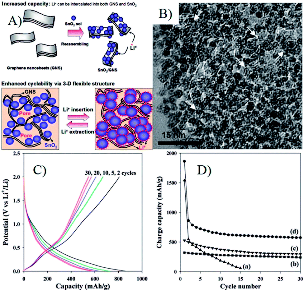 | ||
| Fig. 2 (A) Schematic illustration for the synthesis and the structure of SnO2/GNS; (B) TEM image of SnO2/GNS, the white arrows denote the GNSs; (C) charge/discharge profile for SnO2/GNS; (D) cyclic performances for (a) bare SnO2 nanoparticle, (b) graphite, (c) GNS, and (d) SnO2/GNS.65 Reproduced with permission from ref. 65, Copyright (2009) American Chemical Society. | ||
Due to the abundant oxygen-containing functional groups, GO and RGO are usually negatively charged, and they can easily form composites with positively charged MOs by a co-assembly process via electrostatic interactions. However, the pre-fabricated MOs are always negatively charged or neutral (e.g. Co3O4 and Fe3O4 nanoparticles are always terminated by OH functional groups74,75), and thus MOs are usually modified by grafting method. For example, Feng et al. grafted aminopropyltrimethoxysilane (APS) to OH terminated Co3O4 or Fe3O4 nanoparticles to render positively charged oxides in an acidic solution.74 In addition to APS, various positively charged compounds, such as poly dimethyl diallyl ammonium chloride (PDDA), (3-aminopropyl) trimethoxysilane (APTMS) and poly(allylamine hydrochloride) (PAH), were also used.76–79 However, the method is not suitable to metal hydroxides due to their dissolution in acid solution. Zhang et al. described a general strategy to fabricate graphene coated large-area Co(OH)2 heterostructures by assembling the positively charged hydroxide nanosheets and negatively charged functionalized graphene in a nearly neutral solution (Fig. 3A and B).72 Then, they developed a modified method to prepare binder free and mechanically robust CoO/graphene electrodes (Fig. 3C and D). The negatively charged RGO or GO can also be positively charged by surface grafting, such as amine-functionalized graphene.80 3D MOs–G composites fabricated via electrostatic interactions are always in encapsulated and layered models. The large surface area of graphene and strong intermolecular forces between MOs and graphene can make MOs nanoparticles disperse well on graphene and prevent their aggregation, which are also beneficial for the stability and high electrical conductivity of composites. Furthermore, graphene is usually in the microscale, which can ensure that the self-assembled MOs nanostructures are effectively covered or supported by graphene, and the porous nature, generated by the co-assembly process, can facilitate ion diffusion and accommodate the volume change during the cycle processes.
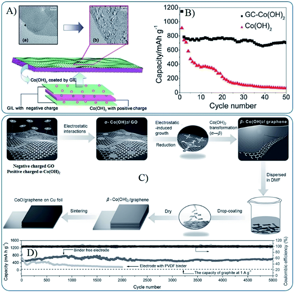 | ||
| Fig. 3 (A) Schematic diagram of the fabrication of sandwich structured GC–Co(OH)2 heterostructures driven by the mutual electrostatic interactions between the two species; (B) cyclic performances for GC–Co(OH)2 and pure Co(OH)2 (ref. 72). Reproduced from ref. 72 with permission from The Royal Society of Chemistry. (C) Schematic diagram of the fabrication of CoO/graphene hybrid on Cu foil; (D) reversible Li extraction capacity of CoO/graphene hybrid electrode at 1 A g−1 for 5000 cycles.73 Reproduced with permission from ref. 73, Copyright (2013) WILEY-VCH. | ||
Metal ions from inorganic and/or organic metal salts can also be absorbed on the surface of negatively charged RGO or GO via electrostatic interactions or coordination bonds in RGO or GO suspensions. Starting from the metal ion–GO/RGO dispersions, wet-chemistry strategies, such as in situ chemical deposition, sol–gel processes and hydro-/solvothermal synthesis, are widely used to fabricate a broad range of MOs–G composites. In these strategies, suspended RGO/GO acts as a 2D precursor to form an integrated support network for discrete metal ions, and then composites are formed by hydrolysis or in situ redox reactions to anchor MOs on the surface of RGO, and further followed by various reducing and annealing processes. Special emphasis is that graphene can suppress the agglomeration of MOs nanoparticles during the preparation process.49 Researches indicated that Co3O4 nanoparticles with a size of 5–20 nm were homogeneously anchored on the surface of graphene, while sub-microparticles were obtained without graphene (Fig. 4).81 Furthermore, the presence of graphene can also affect the morphology of MOs. Our research indicated 1D Co3O4 nanorods were generated instead of aggregated nanoparticles when GO was added to an alcohol–water mixed solvent.82 At present, wet chemistry strategies are widely used to fabricate 3D MOs–G composites, which provide simple and practical methods to obtain a uniform distribution of MOs nanostructures anchored on graphene with controlled size, morphology and crystallinity.49
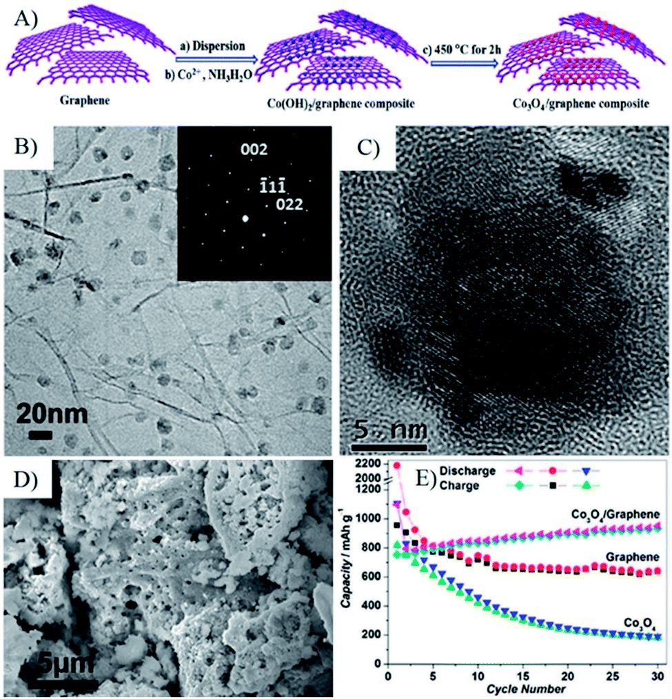 | ||
| Fig. 4 (A) Schematic representation of the fabrication process of a Co3O4/graphene composite. (B and C) TEM and HRTEM images of Co3O4/graphene composite; the inset in (B) is the SAED pattern of Co3O4 NPs with [110] plane in the Co3O4/graphene composite, indicative of the well-textured and single-crystalline nature of Co3O4 NPs. (D) SEM image of the as-prepared Co3O4, which shows that only micro-sized Co3O4 particles can be formed without the presence of graphene sheets. (E) Cycling performance for graphene, Co3O4, and the Co3O4/graphene composite.81 Reproduced with permission from ref. 81, Copyright (2010) American Chemical Society. | ||
Surfactants are commonly used in the fabrication of stable graphene dispersions and synthesizing MOs nanostructures.62,83–85 Anionic sulphate could help the thermal reduced graphene dispersion in aqueous solution and facilitate the self-assembly of the in situ grown nanocrystalline TiO2.86 The method is further developed to fabricate ordered mesoporous MOs–G nanocomposites, such as SnO2, NiO or MnO2–graphene composites.87 In addition to the stabilization of graphene in aqueous/solvent solutions, surfactants can also control the size and morphology of MOs in the wet chemistry strategy. Co3O4–graphene nanocomposites with high loading and highly dispersed Co3O4 nanoparticles were fabricated by the co-assembly of polyvinylpyrrolidone (PVP) protected precursors and GO, while Co3O4 nanoparticles would agglomerate without a surfactant.88 With the help of the in situ formed dehydroascorbic acid, oxidized product of L-ascorbic acid, GNSs decorated with ultra-small Fe3O4 nanoparticles were synthesized from an Fe3+–GO suspension and L-ascorbic acid via the hydrothermal method.89 SnO2 nanorods/graphene nanocomposites have been synthesized through a simple ultrasonic combined hydrothermal process with the assistance of mercaptoacetic acid.90 Moreover, the approach can be extended to produce other MOs nanostructures on the surface of graphene, such as mesoporous spheres,91–94 nanospindles,95,96 nanorods,97–99 nanowires,100,101 nanotubes,102 nanoplates,103 nanobelts,104,105 nanosheets106–108 and 3D hierarchical structures.109,110
In wet chemistry strategies, the reduction of GO to RGO or graphene can be carried by many methods, such as the metal ion (Fe2+, Sn2+) in situ reduction process,111–115 chemical reduction process,89,116–120 hydro-/solvothermal reduction,90,101,116,121–126 and thermal reduction.127–131 Post thermal reduction under an inert atmosphere is always introduced to increase the electronic conductivity of composites and further enhance the rate capability of LIBs. Furthermore, proper heat treatment can cause graphene crosslinking and wrapping, resulting in a more stable composite structure and leading to good cyclic stability. Based on the wet chemistry strategy, several novel and effective processes have been developed. Considering metal ions–GO/RGO suspension as a sol, MnO–132 and Fe3O4 (ref. 133)–graphene composites have been prepared by the modified sol–gel method via solvent evaporation and thermal reduction in sequence. Electrostatic spray deposition,134 electrostatic induced spread73 and electrospun technology135,136 were also introduced to synthesize MOs–graphene composites. Binder free electrodes synthesized by these methods always showed good cyclic stability and rate capability because of the well dispersed/wrapped MOs nanomaterials and interconnected high electronic conductive graphene 3D network (Fig. 5).
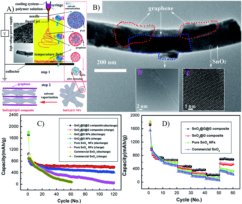 | ||
| Fig. 5 Illustration of the synthetic process (A), TEM (B), cyclic (C) and rate (D) performances of SnO2@G NFs.135 Reproduced from ref. 135, Copyright (2014) with permission from Elsevier. | ||
The microwave heating technique was successfully applied to synthesize nanomaterials in past years. Magnetite/graphene137 or Co3O4–graphene sheet-on-sheet nanocomposites138 have also been prepared by this method. However, the obtained composites still needed a post thermal reduction process. Pinna et al. invented a one-pot non-aqueous synthesis method of crystalline SnO2- and Fe3O4-based graphene heterostructures in 5–10 minutes by combining microwave heating and the ‘benzyl alcohol route’ together, which allowed the selective growth of MOs nanoparticles on the surface of GO. To date, microwave based approaches have been utilized to synthesize Fe2O3–RGO composites,139,140 sheet-like and/or fusiform CuO nanostructures grown on graphene, SnO2–RGO composites,141,142 Mn3O4–G composites,143 Cu2O@Cu–graphene composites,144 MoO3/graphene film123 and Zn2GeO4/N-doped graphene nanocomposites.97
Other special technologies have also been developed to prepare MOs–G composites, such as photocatalytic synthesis,146 coelectrodeposition,147 atomic layer deposition,148 supercritical alcohols/CO2 (ref. 149–151) and template methods.145 Especially, the template method is an effective process to generate 3D MOs on graphene (Fig. 6). No matter what is the method, the key points in the synthesis of 3D MOs–G composites are (1) generating well dispersed and tightly fixed MOs on graphene, (2) enhancing the electron conductivity of graphene, (3) producing a porous structure to make electrolyte accessible and facilitate the Li+ diffusion, (4) low cost and environmental friendly.
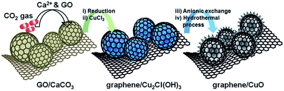 | ||
| Fig. 6 Schematic illustration of sequential steps for the synthesis of graphene/CuO. GO/CaCO3 prepared by applying CO2 gas to Ca2+ and GO suspension. Graphene/Cu2Cl(OH)3 was formed by the chemical reduction of GO to graphene and transformation of CaCO3 into Cu2Cl(OH)3. Graphene/CuO was synthesized from graphene/Cu2Cl(OH)3 by anionic exchange and a hydrothermal process.145 Reproduced from ref. 145 with permission from The Royal Society of Chemistry. | ||
3 3D MOs–G composites in LIBs
MOs in MOs–G composites were mainly in the 0D morphology in the early studies, such as nanoparticles65,86 and nanocubes.234 These nanoparticles usually suffer from aggregation problems even in graphene composites and could be easily peeled off from the surface of graphene due to the weak contact between nanoparticles and graphene during the cycling process, resulting in the fast fading of the electrode capacity. Composites in wrapped, encapsulated, sandwich-like and layered models can show higher cyclic capability than that of other models. However, the rate capability of these composites is usually limited by the diffusion of lithium ions because Li+ ions cannot pass through the microsized planar GNSs. If the size of the nanoparticles is not large enough, the pores between GNSs will be too small to access the electrolyte and is harmful for lithium diffusion. It is important to investigate the size effects of 0D nanoparticles and their dispersion on GNSs to improve electrochemical performances. These problems also can be solved well by the graphene composites consisting of 1D, 2D or 3D MOs materials, which have at least one dimension in the micro or sub-micro size. In this situation, MOs with 1D, 2D and 3D structures can afford more sites to connect with graphene and create many meso- or macropores to make it electrolyte accessible, which can further enhance the long term stability and rate capability of LIBs. Furthermore, holey GNSs and stable 3D graphene structures can facilitate the diffusion of lithium ions and increase the rate capability. Thus, the morphology and size of MOs or graphene in composites play important roles in the electrochemical performances of LIBs.3.1 Morphologies of MOs in composites
The assembling type, pore size/structure, surface area and overall dimensions of 3D MOs–G composites are greatly affected by the morphology and size of MOs. Moreover, the properties of 3D MOs–G composites will affect the stability of the hierarchical structure, the access of electrolytes, the diffusion of lithium ions, and further affect the electrochemical performances of LIBs.| MOs–Ga Composites | MOs Morphology | Synthesis method | MO content (wt%) | ICEb | Cyclic performance | Rate performance | Ref. | ||||
|---|---|---|---|---|---|---|---|---|---|---|---|
| Current density (mA g−1) | Initial capacity (mA h g−1) | Cycles | Remain capacity (mA h g−1) | Current density (mA g−1) | Capacity (mA h g−1) | ||||||
| a G: graphene.b ICE: initial columbic efficiency.c C: carbon. | |||||||||||
| Graphene composites with 0D MOs | |||||||||||
| Co3O4/CoO–G | Nanoparticles | Auto-combustion synthesis | 90 | 76 | 21 | 890.4 | 30 | 801.3 | 2100 | 284 | 152 |
| Co3O4–G | Nanoparticles | PVP assistant reflux | 71 | — | 40 | 1300 | 40 | 860 | 1000 | 400 | 88 |
| Co3O4–G | Nanocrystals | Hydrothermal method | 76 | 70.1 | 400 | ∼900 | 50 | 775.2 | 2000 | 460 | 153 |
| Co3O4–G | Polyhedral particles | Hydrothermal method | — | ∼65 | 50 | 800 | 80 | 885 | 700 | 395 | 122 |
| CoFe2O4–G | Nanoparticles | Coprecipitation & thermal reduction | 82.3 | ∼71 | 100 | 982 | 50 | 985 | 1600 | 509 | 154 |
| CoFe2O4–G | Nanoparticles | Hydrothermal method & thermal reduction | 77.5 | 69 | 100 | 899 | 70 | 921.8 | 1600 | 446.3 | 130 |
| CoO–G | Octahedral nanocrystals | Thermal decomposition | 40.7 | 60.30 | 100 | 1184 | 60 | 1401 | 8000 | ∼500 | 155 |
| Cr2O3–Cc–G | Nanoparticles | Hydrothermal method & thermal reduction | 41.9 | 72.50 | 106 | 894.5 | 100 | 630 | 1000 | 315 | 131 |
| SnO2–C–G | Nanoparticles | Evaporation & thermal reduction | — | 65.80 | 200 | 656.9 | 100 | 633.2 | 1600 | 379.5 | 156 |
| SnO2–C–G | Nanoparticles | Hydrothermal method | 50.3 | ∼51 | 50 | 756 | 150 | 470 | 124 | ||
| CuO–G | Nanoparticles | Spex-milling | 90 | 47.20 | 0.1 mA cm−2 | 785.2 | 45 | 496.5 | 6.4 mA cm−2 | 201 | 70 |
| Fe2Mo3O8–G | Nanoparticles | Hydrolysis & thermal reduction | 91.7 | 72.40 | 200 | 923.5 | 40 | 835 | 3000 | 574.8 | 157 |
| Fe2O3/SnO2–G | Nanoparticles | Hydrothermal method-in situ reduction | 82 | 63.30 | 400 | 746 | 100 | 700 | 8410 | 139 | 158 |
| Fe2O3–C–G | Nanoparticles | Evaporation & thermal reduction | — | — | 500 | ∼500 | 100 | 504 | 2000 | 288.6 | 156 |
| Fe2O3–C–G | Sub-microparticles | Hydrothermal method & glucose impregnation-pyrolysis process | 85 | 71 | 200 | 1097 | 50 | 1005 | 159 | ||
| Fe2O3–G | Nanoparticles | Hydrothermal method | 32 | ∼60 | 100 | 1000 | 50 | 810 | 2500 | 280 | 160 |
| Fe2O3–G | Nanoparticles | Spray drying | 86.7 | 72 | 100 | 756 | 25 | 870.5 | 1600 | 660 | 161 |
| Fe2O3–G | Nanoparticles | Hydrothermal method | 68 | 56.30 | 200 | 800 | 200 | 852 | 4000 | 425 | 162 |
| Fe2O3–G | Microsphere | Hydrothermal method | 70 | 77.20 | 50 | 899 | 50 | 1206 | 1000 | 534 | 163 |
| Fe2O3–G | Nanoparticles | Hydrothermal method & freeze–drying process | 78 | 69 | 100 | 1045 | 50 | 995 | 2000 | 624 | 164 |
| Fe2O3–G | Nanoparticles | Hydrothermal method | 73 | ∼69 | 100 | 1095 | 70 | ∼950 | 800 | ∼700 | 165 |
| Fe2O3–G | Nanoparticles | Thermal decomposition | 68.1 | 53 | 100 | 750 | 50 | 900 | 5000 | 500 | 166 |
| Fe2O3–G | Nanoparticles | PVP hydrolysis | 80 | 77 | 200 | 1107 | 50 | 1052 | 2000 | 690 | 167 |
| Fe3O4–CNF–G | Nanoparticles | Wet immersion method | 41.6 | ∼60 | 1000 | 1400 | 100 | 1427.5 | 5000 | 592 | 168 |
| Fe3O4–G | Nanoparticles | Solution mixing method | 78 | 63.40 | 500 | 902 | 100 | 892 | 2000 | 672 | 169 |
| Fe3O4–G | Nanoparticles | Supercritical CO2–ethanol | 75 | 73.50 | 1000 | 941 | 100 | 838 | 5000 | 460 | 151 |
| Fe3O4–G | Nanoparticles | Solution mixing & thermal reduction | — | 66.90 | 100 | 908.6 | 50 | 1082 | 6000 | 145 | 170 |
| Fe3O4–G | Nanoparticles | Thermal evaporation & thermal reduction | 78 | 67.30 | 200 | 1443 | 100 | 868 | 1000 | 539 | 133 |
| Fe3O4–G | Nanoparticles | Microwave assisted “benzyl-alcohol route” | 58.9 | 55.70 | 100 | 1050 | 1600 | ∼500 | 140 | ||
| Fe3O4–G | Nanoparticles | Electrostatic self-assembly | 55.5 | 59.90 | 200 | 674 | 100 | 540 | 2000 | 384 | 76 |
| Fe3O4–G | Nanoparticles | Hydrolysis | — | 61 | 92.8 | 814 | 4860 | 282 | 171 | ||
| Fe3O4–G | Nanoparticles | Hydrothermal method | 30 | 59.20 | 100 | 1037 | 200 | 1130 | 1600 | 648 | 172 |
| Fe3O4–G | Nanoparticles | Hydrothermal method | 82.2 | 65 | 900 | 960 | 133 | 833 | 1800 | 437 | 89 |
| Fe3O4–G–G | Nanospheres | Electrostatic interactions and hydrothermal method | 93.7 | ∼67.3 | 93 | 920.3 | 150 | 1059 | 4800 | 363 | 75 |
| FeOOH–G | Nanoparticles | Infrared irradiation | 69 | 67.10 | 1000 | ∼800 | 600 | 767 | 2000 | 608 | 173 |
| G–Co3O4–G | Nanoparticles | Hydrothermal method & mixing method | 46.1 | ∼69.5 | 89 | 820 | 50 | 715.3 | 892 | 310 | 174 |
| GeOx–G | Nanoparticle | Thermal Ge/Sn co-evaporation | 70 | 51.10 | 325 | 1047 | 100 | 1008 | 5850 | 723 | 175 |
| G–NiO–G | Nanoparticles | Hydrothermal method and mixing method | 44.1 | 54.90 | 72 | 639.4 | 50 | 617.6 | 174 | ||
| La2O3–NiO–G | Nanoparticles | Physical mixing | 50 | 53.00 | 50 | 458.6 | 100 | 418.2 | — | — | 176 |
| Mn3O4–G | Nanoparticles | Hydrothermal method | 64 | 62.70 | 200 | 900 | 40 | 800 | 2000 | 382 | 121 |
| MnFe2O4–G | Nanoparticles | Ultrasonic process | 90 | 60 | 100 | 949 | 50 | 1017 | 12![[thin space (1/6-em)]](https://www.rsc.org/images/entities/char_2009.gif) 000 000 |
315 | 67 |
| MnO2–G | Nanoparticles | Hydrothermal method | — | 64 | 100 | 781.5 | 50 | 750 | 1000 | 465.2 | 177 |
| MoO2–G | Nanoparticles | In situ reduction process | 93.5 | 75.40 | 0.2 C | 1067.7 | 100 | 950 | 10 C | 411.7 | 178 |
| MoO3–G | Nanoparticles | Solution mixing method | 73.96 | — | 800 | 961.5 | 50 | 711 | 179 | ||
| NiFe2O4–G | Nanoparticles | Coprecipitation & thermal reduction | 87.9 | ∼72 | 100 | 1225 | 50 | 1005 | 1600 | 758 | 154 |
| NiO–G | Nanoparticles | Supercritical CO2–ethanol | 68.5 | 65.10 | 500 | 629 | 100 | 741 | 2000 | 350 | 150 |
| NiO–G | Nanoparticles | Electrochemical | 87.3 | 59.30 | 359 | 754 | 50 | 586 | 1440 | ∼500 | 180 |
| SnO2–C–G | Nanoparticles | Hydrothermal method & thermal reduction | 51.4 | 54 | 100 | 1115 | 100 | ∼1000 | 1000 | 499 | 128 |
| SnO2–C–G | Nanoparticle | Hydrothermal method & carbonization process | 74.5 | 60 | 100 | 1058 | 80 | 703 | 1000 | 443 | 181 |
| SnO2–C–G | Nanoparticles | Evaporation & thermal reduction | — | 65.80 | 200 | 656.9 | 100 | 633.2 | 1600 | 379.5 | 156 |
| SnO2–C–G | Nanoparticles | Hydrothermal method | 50.3 | ∼51 | 50 | 756 | 150 | 470 | 124 | ||
| SnO2–G | Nanoparticles | Refluxed & cross-linking reaction | 81.8 | — | 100 | 1282 | 50 | 521 | 2000 | 334 | 111 |
| SnO2–G | Nanoparticles | Microwave & thermal reduction | 85 | 54.40 | 100 | 1329.4 | 20 | 618 | 129 | ||
| SnO2–G | Nanocrystals | In situ Sn2+ reduction | 72 | 54 | 100 | 1017 | 50 | 610 | 2000 | 372 | 182 |
| SnO2–G | Nanoparticles | Polyol reduction | 30 | 73 | 90 | 1890 | 100 | 1220 | 1000 | 602 | 183 |
| SnO2–G | Quantum dots | Hydrothermal method | 50 | ∼43 | 200 | 800 | 200 | 720 | 2000 | 400 | 184 |
| SnO2–G | Nanoparticles | Wet chemical method | 80 | 96.4 | 1000 | 1923.5 | 40 | 1545.7 | 112 | ||
| SnO2–G | Nanoparticle | Unzipping CNT and ultrasonication | 80 | 74 | 100 | 1129 | 50 | 825 | 2000 | 580 | 185 |
| SnO2–G | Nanoparticle | Sn2+ in situ reduction & self-assembly | — | ∼39 | 100 | ∼900 | 60 | 602 | 1000 | 200 | 186 |
| SnO2–G | Nanoparticles | Template | 89 | ∼51 | 100 | 878 | 40 | 503 | 187 | ||
| SnO2–G | Nanoparticle | Hydrothermal method assembly | 53 | 56 | 100 | 1211 | 70 | 824 | 500 | 621 | 188 |
| SnO2–G | Nanoparticle | Sn2+ oxidation–reduction reaction | 68.1 | 45.60 | 100 | 1254.6 | 30 | 985.5 | 189 | ||
| SnO2–G | Nanoparticle | Sn2+ ultrasonic & oxidation–reduction reaction | 38.4 | ∼62 | 100 | 627 | 50 | 535 | 190 | ||
| SnO2–G | Nanocrystals | Freeze–drying & Vapor reduction process | 70 | 61.30 | 500 | 1144 | 500 | 1346 | 20000 |
417 | 191 |
| SnO2–GO–G | Nanoparticles | Electrostatic interactions | 72.9 | 55.90 | 100 | ∼1100 | 200 | 872 | 2000 | 519 | 80 |
| SnO2–In2O3–G | Nanocrystals | Solvothermal | 90.37 | 57.20 | 60 | 907 | 50 | 551 | 600 | 393 | 192 |
| SnO2–In2O3–G | Nanocrystals | Hydrolysis-chemical reduction & thermal reduction | 50 | 66.40 | 75 | 770 | 30 | 570 | 900 | 504 | 193 |
| SnOx–CNF@G–G | Nanoparticles | Electrospinning calcination & mixing method | 72 | 62.3 | 70 | 838 | 180 | 504 | 700 | 300 | 136 |
| SnWO4–G | Nanoparticle | Hydrothermal method | 80 | 55 | 50 | 934 | 20 | 500 | 194 | ||
| TiO2–G | Nanocrystals | Hydrothermal method | 93.7 | 69.30 | 200 | 171 | 100 | 137 | 4000 | 69 | 195 |
| TiO2–G | Nanoparticles | In situ hydrothermal method growth | 65 | 58.50 | 200 | 237 | 100 | 157 | 2000 | 122 | 196 |
| TiO2–G | Nanoparticles | Hydrolysis & hydrothermal method | 83 | 0.2 C | 226 | 20 C | 97 | 197 | |||
| TiO2–G | Nanoparticle | Gas/liquid interface reaction | — | — | 1000 | ∼150 | 80 | 136 | 5000 | 109 | 198 |
| TiO2–G | Nanoparticles | Atomic layer deposition | 54.7 | 2000 | 100 | 500 | 95 | 199 | |||
| TiO2–SnO2–G | Nanoparticles | Solvothermal & hydrothermal method | 90 | 49 | 50 | 954 | 50 | 537 | 1000 | 250 | 200 |
| V2O5–G | Quantum dots | Two-step solution phase synthesis | 93.55 | 97.20 | 100 | 280 | 100 | 212 | 1000 | 118 | 201 |
| V2O5–G | Nanoparticles | Hydrothermal method | 92 | — | 20 | 235 | 100 | 171 | 202 | ||
| Zn2SnO4–G | Nanocrystals | Hydrothermal method | 82.6 | 54 | 200 | 911 | 50 | 688 | 1600 | 439 | 203 |
| ZnFe2O4–G | Nanoparticles | Hydrothermal method | — | 68.70 | 100 | 945 | 50 | 956 | 1000 | ∼600 | 204 |
| ZnO–G | Quantum dots | Atomic layer deposition | 68 | ∼50 | 100 | 700 | 100 | 540 | 1000 | 400 | 205 |
| ZnWO4–G | Nanoparticles | Sol–gel method | 93 | 68 | 50 | 695 | 20 | 585 | 200 | 440 | 206 |
|
|||||||||||
| Graphene composites with 1D MOs | |||||||||||
| CuGeO3–G | Nanowires | Nanowires | 81.2 | 45.5 | 100 | 1157 | 130 | 780 | 2000 | 550 | 207 |
| Fe3O4–G | Nanospindles | Hydrothermal method | — | — | 100 | 745 | 200 | 558 | — | — | 95 |
| Fe3O4–G | Hollow nanospindles | Vacuum filtration and thermal reduction | 70.3 | 66.7 | 200 | ∼1000 | 50 | 940 | 2000 | 420 | 208 |
| Fe3O4–G | Nanorods | In situ growth | 75 | 60.2 | 928 | 912 | 100 | 867 | 4640 | 569 | 209 |
| GeO2–G | Microtubes | Strain-driven method | 88.6 | 33 | 110 | 856 | 100 | 919 | 2200 | 571 | 210 |
| MnO2–G | Nanowires | Hydrothermal method route | 85 | — | 60 | 1150 | 30 | 890 | 12000 |
∼600 | 101 |
| MnO2–G | Nanorods | Solution mixed & thermal annealing method | 91 | 70.8 | 30.8 | 170.6 | 100 | 158.3 | — | — | 211 |
| Ni-doped MnO2–G | Nanowires | Electrostatic interactions | 70 | 95 | 286 | ∼170 | 40 | 122 | — | — | 212 |
| SnO2@G@G–G | Nanowires | Electrospinning & solution mixed method | 72 | 61.6 | 80 | 1050 | 180 | 591.9 | 4000 | 212.8 | 135,213 |
| SnO2–C–G | Nanorod | Seed assisted hydrothermal method growth & nanocarbon coating | 63 | 70 | 100 | 1285 | 150 | 1419 | 3000 | 540 | 214 |
| SnO2–G | Nanorods | Ultrasonic & hydrothermal method | 67 | ∼60 | 200 | 1153 | 100 | 1107 | 2000 | 583.3 | 90 |
| TiO2–G | Nanotube | Hydrothermal method | — | — | 100 | 334 | 50 | 255 | 8000 | 80 | 102 |
| TiO2–G | Nanowires | Hydrothermal method | 90.4 | — | 150 | ∼200 | 30 | ∼160 | — | — | 215 |
| TiO2–G | Nanotubes | Hydrothermal method | 95.91 | 98.9 | 150 | ∼210 | 30 | 278 | 1500 | 114 | 216 |
| WO3–G | Nanowires | Hydrothermal method | 92.1 | 67.4 | 100 | 622 | 100 | 656 | 290 | 800 | 100 |
| Zn2GeO4/G–G | Nanorods | Ion-exchange method | 87.9 | >60 | 100 | 873 | 90 | 803 | 3200 | 522 | 217 |
| Zn2GeO4–G | Nanorods | Hydrothermal method & microwave process | 72.2 | ∼60 | 100 | 873 | 100 | 1044 | 3200 | 678 | 97 |
| Zn2GeO4–G | Hollow nanorods | Hydrothermal method | — | — | 100 | — | 20 | 900 | — | — | 218 |
|
|||||||||||
| Graphene composites with 2D MOs | |||||||||||
| CoO–G (binder free) | Nanosheets | Electrostatic induced spread | 87 | 71.60 | 500 | 678 | 150 | 640 | 1000 | 604 | 73 |
| CuO–G–G | Nanosheets | Vacuum filtration & hydrothermal method reduction | — | 91.60 | 67 | 782.3 | 50 | 736.8 | 219 | ||
| Fe2O3–CNT–g–G | Nanoring | Chemical vapor deposition | — | ∼51 | 74.4 | 984 | 100 | 812 | 3720 | 534 | 220 |
| Fe2O3–G | Hexagonal nanoplatelets | Surfactant assistant limited growth | 53 | 0.2 C | 1370 | 150 | 1100 | 5 C | 631 | 221 | |
| Fe2O3–G | Nanodisk | Hydrothermal method | 75.6 | 71.60 | 200 | 1088 | 50 | 931 | 10000 |
337 | 127 |
| MoO3–G | Nanobelts | Hydrothermal method | — | — | 500 | 289 | 200 | 174 | 1000 | 238 | 105 |
| MoO3–G | Nanobelt | Microwave hydrothermal method | 70 | 59 | 100 | 291 | 100 | 172 | 2000 | 151 | 123 |
| SnO2 | Nanosheets | Hydrothermal method | 87 | 71.40 | 100 | 975 | 100 | 451 | 222 | ||
| TiO2/graphene sandwich paper–G | Nanosheets | In situ hydrothermal method | 82 | — | 1680 | ∼150 | 100 | 147 | 8500 | 120 | 223 |
| TiO2/SnO2–G | Hybrid nanosheets | Stepwise growth | 95 | 49 | 160 | 841 | 300 | 600 | 4000 | 300 | 224 |
| TiO2@Co3O4–G | Coaxial nanobelt arrays | Electrostatic self-assembly | 51.1 | 51 | 100 | 364 | 60 | 437 | 800 | 204 | 77 |
| TiO2–G | Nanosheets | Hydrothermal method | 75.12 | — | 1 C | 232 | 100 | 189 | 10 C | 150 | 107 |
| TiO2–G | Nanoplatelets | Solvothermal | 78 | 92 | 1 C | 404 | 100 | 350 | 10 C | 165 | 108 |
| TiO2–G | Nanobelts | Hydrothermal method | 86 | 82 | 150 | 746 | 100 | 430 | 3000 | 210 | 104 |
| V2O5–G | Nanosheets | Solvothermal | 95 | 89 | 600 | 262 | 160 | 102 | 3000 | 138 | 225 |
| VO2–G | Ribbons | Hydrothermal method & chemical reduction process | 84 | — | 190 C | 204 | 1000 | ∼190 | 117 | ||
| VO2–G | Nanosheet | Hydrothermal method | 69 | — | 50 | 418 | 50 | 251 | 5000 | 102 | 226 |
| Zn2SiO4–C–G | Layered structure | Hydrothermal method & vaporization | 80 | 47 | 50 | 738 | 50 | 778 | 1000 | 277 | 119 |
|
|||||||||||
| Graphene composites with 3D MOs | |||||||||||
| Co3O4–G | Mesoporous hollow sphere | Solvothermal & immersed methods | 76.2 | 69.30 | 1000 | ∼900 | 200 | ∼700 | 5000 | 259 | 94 |
| Co3O4–G paper–G | Porous fibers | Electrostatic self-assembly | 78.3 | 71.60 | 100 | 1005.7 | 40 | 840 | 100 | 295 | 79 |
| Cu2O@Cu–G | Porous nanospheres | Microwave | 85.2 | — | 50 | 734 | 50 | 842 | 2000 | 410 | 144 |
| Fe2O3–G | Porous nanocages | Template method | — | 76 | 200 | 1239 | 50 | 864 | 5000 | 587 | 227 |
| Fe3O4/G–G | Porous nanorods | In situ-growth & hydrogen plasma treatment | 79 | 77.50 | 500 | 845 | 100 | 890 | 3000 | 520 | 228 |
| Fe3O4/G–G | Interconnected nanoparticles | Template synthesis | 74 | 63.40 | 500 | 965 | 100 | 1124 | 10000 |
506 | 229 |
| Fe3O4–C–G | Mesoporous carbon supported | Template synthesis & heterocoagulation method | 62.4 | 63.40 | 92.4 | 845 | 100 | 660 | 924 | 380 | 230 |
| In2O3/G–G | Mesoporous | Template synthesis & heterocoagulation method | 87.4 | 60.80 | 58 | 804.5 | 100 | 480 | 580 | 290 | 231 |
| Mn0.5Co0.5Fe2O4–G | Mesoporous nanospheres | Solvothermal method | 97.9 | 59.10 | 200 | 846.2 | 200 | 886.1 | 5000 | 266.3 | 93 |
| NiO–C–G | Mesoporous carbon supported | Template synthesis & heterocoagulation method | 51.8 | 61.80 | 71.8 | ∼820 | 100 | ∼570 | 718 | ∼310 | 230 |
| SnO2–G | Mesoporous | Electrostatic interactions | — | — | 78 | ∼780 | 50 | ∼460 | 118 | ||
| SnO2–G | Mesoporous | Solvothermal method | 79.5 | 69.40 | 78 | 1107 | 50 | 847.5 | 780 | 621.5 | 91 |
| SnO2–G | Porous nanospheres | Electrostatic interaction | 95 | 43.40 | 200 | 750 | 50 | 517 | 1000 | 423 | 232 |
| TiO2–G | Mesoporous nanospheres | Hydrothermal method & freeze–drying | 89 | 69.70 | 0.5 C | 219 | 100 | 197 | 20 C | 124 | 92 |
| Zn2SnO4–G | Hollow box | Chemical etching & heat-process | 65 | 69 | 300 | 1121.2 | 60 | 753 | 2000 | 345 | 233 |
To overcome these problems, surfactants can be induced to prevent the aggregation of MOs in graphene. Cai et al. found the presence of PVP could help the dispersion of Fe3O4 nanoparticles on graphene and result a stable capacity of 892 mA h g−1 after 100 cycles, compared with that of 430 mA h g−1 without PVP (Fig. 7A and B).169 Building strong interactions between MOs and graphene is also a good choice to prevent the aggregation of MO nanomaterials and improve the stability and conductivity of composites, which will be further discussed in the following part. Composites in wrapped, encapsulated or layered models usually show higher cyclic stability than that of other models. For instance, the free-standing flexible nanocomposite films produced from layered graphene with 4 nm nanocrystals show no significant fading over 100 charge/discharge cycles (Fig. 7C and D).87 However, the composites in wrapped and encapsulated models suffer from similar lithium ions diffusion problems because lithium cannot effectively pass through the 2D structure of graphene, which further affects the rate capability. Thus a small pore size in composites in the layered model (depending on the size of the nanoparticles) is harmful for electrolyte wetting and lithium diffusion, especially leading to an active process in initial several cycles and limiting rate capability. Hence, these films only retain a capacity of 225 mA h g−1 at 0.02 A g−1, compared to 760 mA h g−1 at 0.008 A g−1.87 Thus, the structure model, graphene structure, dispersion and stability of MOs nanomaterials on the surface of graphene should be considered at the same time to fabricate 0D MOs based graphene composites with high electrochemical lithium storage performances.
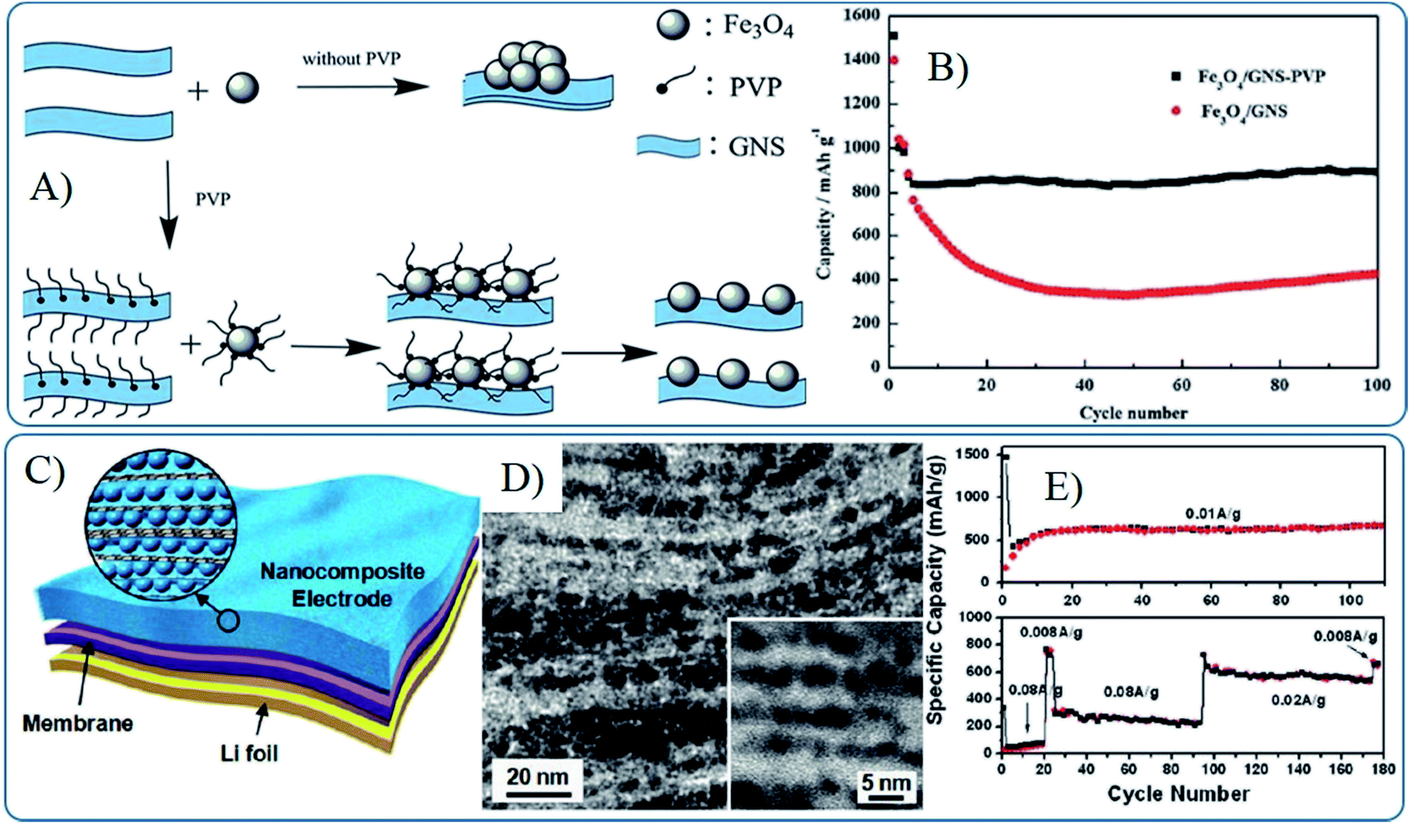 | ||
| Fig. 7 Schematic illustration of the synthesis (A) and cyclic performances (B) of Fe3O4–G composites prepared with the help of PVP.169 Reproduced from ref. 169 with permission from The Royal Society of Chemistry. Li-ion battery configuration (C), cross-sectional TEM images (D) and cyclic performances (E) of a freestanding SnO2–G nanocomposite film as an anode.87 Reproduced with permission from ref. 87, Copyright (2010) American Chemical Society. | ||
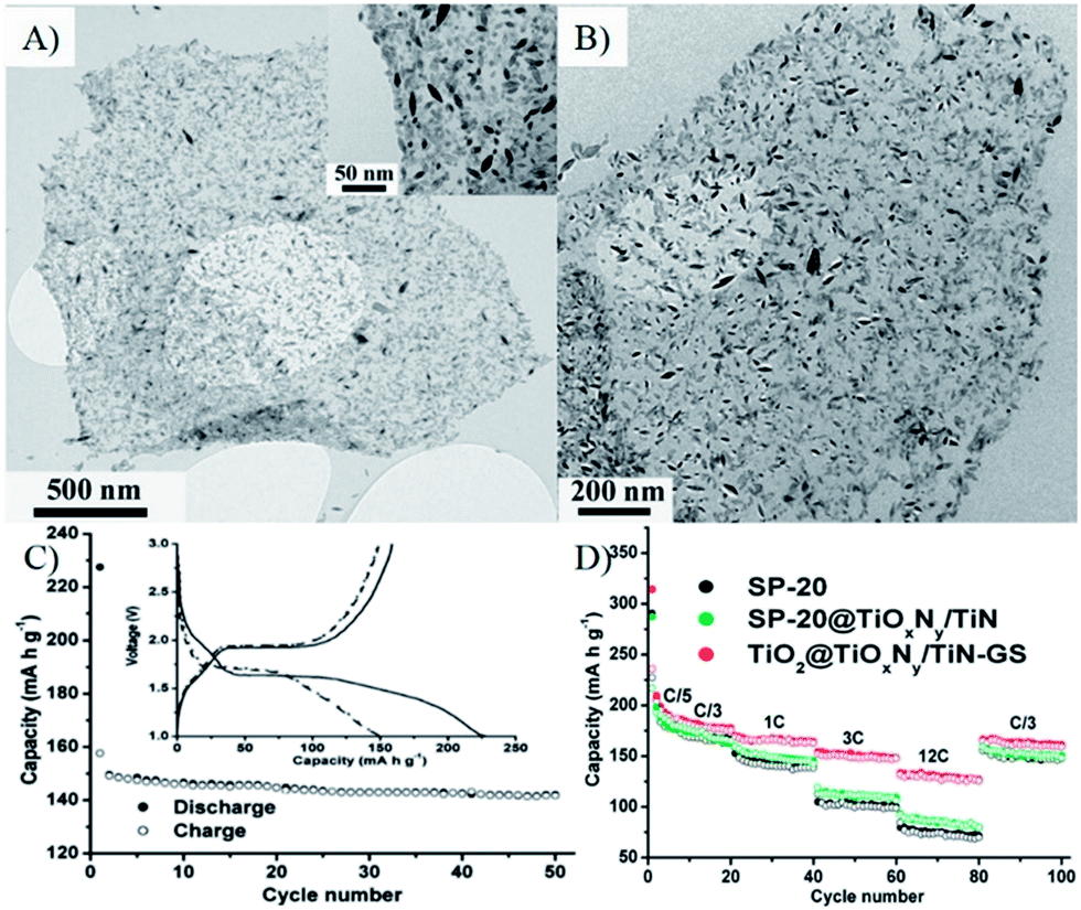 | ||
| Fig. 8 (A) A typical TEM image of a TiO2 nanospindle/graphene oxide nanocomposite (inset is a close-up view); (B) a TEM image of aTiO2@TiOxNy/TiN–G nanocomposite after annealing in NH3. (C) cycling performance of the electrode made of SP-20 at a rate of 1 C (inset shows the voltage profiles). (D) cycling specific capacity profiles of SP-20, SP-20@TiOxNy/TiN, and TiO2@TiOxNy/TiN–G nanocomposite at different charge/discharge rates.235 Reproduced with permission from ref. 235, Copyright (2010) American Chemical Society. | ||
The morphologies of MOs also affect the electron conductivity of composites. Graphene composites with Fe2O3 nanorice (∼200 nm in length and ∼40 nm in diameters) and cube-like nanoparticles (50–100 nm) were control synthesized by a microwave-assisted hydrothermal process.239 The electrical conductivities of Fe2O3 nanoparticles, Fe2O3–GNS particle-on-sheet and Fe2O3–GNS rice-on-sheet are 2.8 × 10⁻⁵ S cm−1, 0.038 S cm−1 and 0.049 S cm−1, respectively, indicating that the composite with 1D Fe2O3 nanoparticles has the highest electron conductivity.239 As shown in Fig. 9, Fe2O3–GNS rice-on-sheet shows superior electrochemical performances compared with that of the particle-on-sheet at both common and high current rates, because the special 1D Fe2O3 nanorice can not only increase electron conductivity, but also facilitate the lithium diffusion rate for their high surface-to-volume ratio. Moreover, the heavy agglomeration of Fe2O3 nanoparticles are more inclined to occur compared with that of the Fe2O3 nanorice.239 Then, graphene–Fe2O3 nanocomposites with different loadings of Fe2O3 nanospindles were prepared by the one-step solvothermal method,96 and the obtained composites showed the higher electron conductivity of 0.10–0.13 S cm−1 (depending on the content of graphene), which further led to an improved rate capability compared with the Fe2O3–GNS rice-on-sheet used as anodes in LIBs.96,239
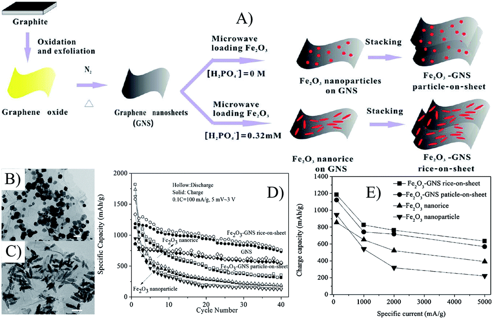 | ||
| Fig. 9 Schematic illustration of the growth process (A), TEM images (B and C), cyclic (D) and rate (E) performances of Fe2O3–GNS particle-on-sheet and rice-on-sheet composites.239 Reproduced with permission from ref. 239, Copyright (2011) American Chemical Society. | ||
 | ||
| Fig. 10 (A) Schematic illustration of the growth process of NiO–GNS sheet-on-sheet and nanoparticle-on-sheet composites; (B) TEM image of NiO–GNS sheet-on-sheet composite; (C) cycling performances at 0.1 C of various anode materials; (D) TEM image of NiO–GNS sheet-on-sheet anode after 40 cycles, E), cycling performances at stepwise increased current rates.241 Reproduced from ref. 241 with permission from The Royal Society of Chemistry. | ||
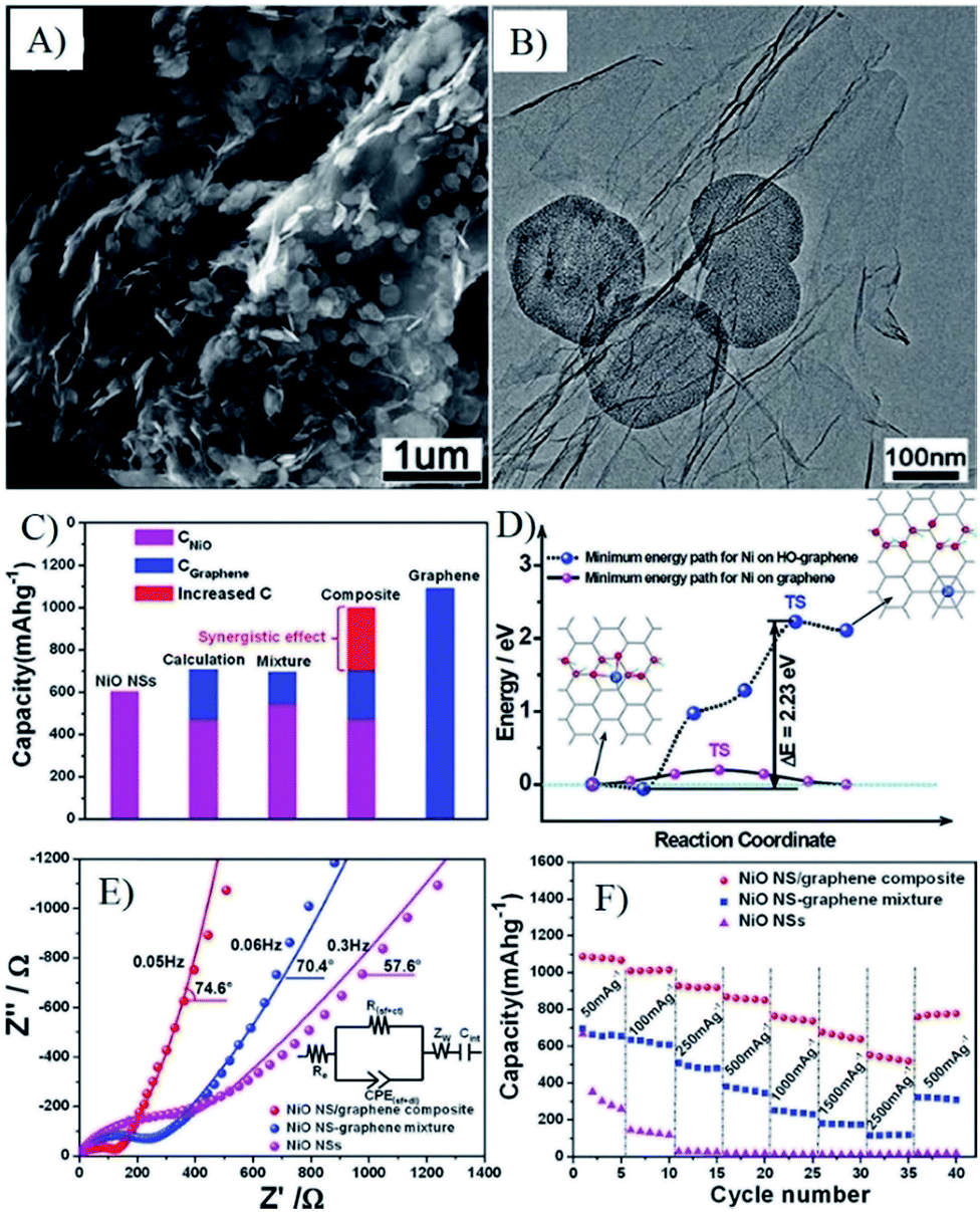
Co3O4 nanorods/GNS nanocomposites were synthesized via a one-pot solvothermal method by simultaneously completing the reduction of GO and the growth of Co3O4 nanorods.82 The obtained Co3O4 nanorods–GNS nanocomposites exhibited approximate 1310 mA h g−1 and 1090 mA h g−1 of capacity at 0.1 A g−1 and 1 A g−1 after 40 cycles, respectively.82 The improvement of electrochemical performances of the Co3O4 nanorods–GNS nanocomposites can be attributed to the unique structures and properties of GNS and Co3O4 nanorods, which can provide an excellent ion diffusion and electronic conduction pathway, and further lead to a superior electrochemical performance. Recently, we further developed a small molecule assistant hydrothermal method to directly grow SnO2 nanorods on GNSs, which were further assembled to a layered structure.90 The as-prepared nanocomposites maintained a reversible capacity of 1107 mA h g−1 within 100 cycles at a current density of 0.2 A g−1, retaining 96.2% of the initial value. The capacity, stability and rate capability of the layered structure are considerably higher than that of single layer monodispersed SnO2 nanorods growth on GNSs,98,99 which may be attributed to the additional stability and electron conductivity derived from the interlayered/interconnected graphene in the layered model composite. The concept is further supported by the high electrochemical performances of free-standing layer-by-layer assembled graphene–MnO2 nanotube thin hybrid films prepared by an ultrafiltration technique.240 In all, the unique physiochemical properties of 1D MOs in tandem with the synergistic effects of graphene composites promise high electrochemical performances in LIBs, which is greatly affected by the size of 1D MOs, graphene quality and the structure models of composites.
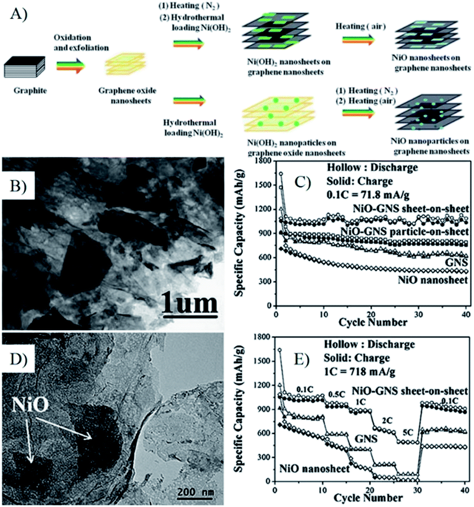
In the graphene composites with 2D MOs nanostructures, the lithium diffusion within 2D MOs may decide their lithium storage performances, especially the high rate performances. Wang et al. synthesized Co(OH)2–graphene sheet-on-sheet composites by a single-mode microwave irradiation method, and layered Co3O4–GNS sheet-on-sheet nanocomposites were obtained after being further post thermally treated under N2 to improve the quality and electron conductivity of graphene.68,81,138,204,243 The unique structure shows good stable electrochemical properties after 30 cycles. In composites, plenty of pores in the composite and Co3O4 nanosheets can accelerate phase transition, restrain the crumbling and cracking of the electrode, and further lead to superior cycling stability. Furthermore, the porous structure of Co3O4 nanosheets is readily accessible for electrolyte, facilitating the transportation of Li+ ions from the liquid to the active surface of Co3O4 and shorten the transportation length for both lithium ions and electrons.138 Thus, the rate performances of composites are significantly improved, and a capacity of 931 mA h g−1 is obtained at a current density of 4450 mA g−1, which is larger than the theoretical capacity of Co3O4 (890 mA h g−1). While only half of the capacity for Co3O4–graphene nanoparticle-on-sheet is obtained at the same conditions.138 Then, they prepared NiO–graphene sheet-on-sheet and nanoparticle-on-sheet nanostructures (Fig. 10), the stable sheet-on-sheet structures showed highly stable reversible capacities (1056–1031 mA h g−1 in 40 cycles at 71.8 mA g−1) and good rate capabilities (492 mA h g−1 at 3590 mA g−1) than those of NiO nanosheets, GNSs, and NiO–graphene nanoparticle-on-sheet.241 Both of the above results and other research106,244,245 indicate that the electrochemical performances of graphene composites with 2D structures are better than the ones of 0D structures, derived from the stable and porous 2D structure.
 | ||
| Fig. 11 Schematic illustration of the formation process (A), TEM images (B and C), cyclic (D) and rate (E) performances of a-Fe2O3 hexagonal nanoplatelets sandwiched between graphene sheets (HP–Fe–G).221 Reproduced from ref. 221, Copyright (2013) with permission from Elsevier. | ||
In addition, the porous structure, ultrathin nanosheets can also reduce the diffusion distance of Li ions, thus the graphene composites with ultrathin Fe2O3 nanosheets (Fig. 11)221 and VO2 ribbons117 show remarkable stability and rate capability as porous 2D structures. These graphene composites with special 2D MOs nanostructures show the following inspirations: (1) the face to face contact model can enhance the electron contact, good mechanical and electrochemical stability of composites; (2) the enhanced electron contact with interconnected graphene networks can lead to high electron conductivity; (3) ultrathin and porous 2D nanostructures can provide numerous channels for the access of the electrolyte and facilitate the rapid diffusion of lithium ions.
Though the one-pot synthesis method of graphene composites with 3D MOs is facile and easy, it lacks universality. Recently, the co-assembly of graphene and 3D MOs has been widely developed to fabricate composites of graphene and 3D MOs, in which mesoporous MOs were pre-synthesized by template methods118,230,231,252,253 or one pot processes.66,94 Furthermore, the template145,227,229 and chemical etching233 methods were also used directly to prepare graphene nanocomposites with 3D MOs. The electrochemical performances of the obtained graphene and 3D MOs composites are decided by the primary particle size, pore structure and post reduction process. Moreover the lithium storage performances, especially the high rate performance, strongly depend on the size of the building units. As shown in Fig. 12, graphene–mesoporous TiO2 nanosphere composites with primary particles of 4 nm in size show a capacity of 97 mA h g−1 at 8.4 A g−1, while the nanocomposites with primary particles of 20–30 nm in size maintain a capacity of 97.7 mA h g−1 at 1.68 A g−1.250,251
 | ||
| Fig. 12 SEM (A and D), TEM (B and E) images and rate capability (C and F) of mesoporous anatase TiO2 nanospheres–graphene composites (A–C)251 and porous TiO2 nanospheres–graphene composites (D–F).250 A–C, Reproduced with permission from ref. 251, Copyright (2011) WILEY-VCH. D and E, reproduced from ref. 250 with permission from The Royal Society of Chemistry. | ||
3.2 Morphologies of graphene
Due to the 2D nature of graphene, Li+ ions are difficult to directly transmit through GNSs. Furthermore, the conductivity between individual graphene nanosheets also affects the rate performances of nanocomposites. Thus, the morphologies, size and structures of graphene in composites are also very important for LIBs. To overcome the above problems, 3D graphene structures (free-standing graphene and graphene oxide sponges) were first synthesized by a special drying process, in which the strong interactions of graphene oxide in water played an important role. After being loaded by MOs nanomaterials and post reduced, the obtained graphene composites showed outstanding electrochemical performances.92,227,255 For example, magnetite modified GNSs maintained a capacity of 450–500 mA h g−1 at 5 A g−1 during 1000 cycles.256 Co3O4 nanoparticles deposited onto porous graphene showed a good cycling performance with 90.6% retention of the original capacity after 50 cycles and enhanced rate capability with 71% capacity retention at 1 A g−1, compared with the capacity at 0.05 A g−1 (Fig. 13).254 Fe2O3 coated three-dimensional (3D) graphene composites maintained a capacity of 864 mA h g−1 at 0.2 A g−1 and 587 mA h g−1 at 5 A g−1 after 50 cycles.227 These 3D frameworks with interconnected porous structures can effectively reduce the diffusion length of electrons and Li+ ions, and the cross-linked graphene network can provide multidimensional pathways to facilitate the transport of electrons in the bulk electrode.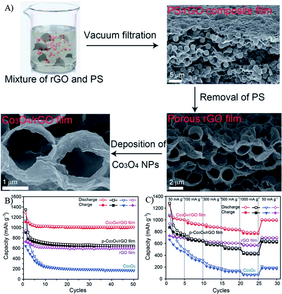 | ||
| Fig. 13 Schematic illustration of the formation process (A), cyclic (B) and rate (C) performances of Co3O4/rGO films.254 Reproduced from ref. 254 with permission from The Royal Society of Chemistry. | ||
Recently, amorphous GeOx coated vertically aligned GNS composites were synthesized by a microwave plasma enhanced chemical vapor deposition system combined with the chemical vapor deposition process,175 in which GNSs formed a fast electron transport channel due to its superior electron conductivity and the vertically aligned sandwich nanoflakes. The unified orientation of GNSs could effectively reduce the vertical lithium diffusion and offer a short pathway for lithium ions.175 Additionally, amorphous GeOx nanoparticles less than 10 nm in size could mitigate the mechanical stress of volume change. Thus, the obtained composites showed a unique cyclic stability (1008 mA h g−1 for 100 cycles with retention of 96%) and rate performance (545 mA h g−1 even at 15 C) (Fig. 14).175
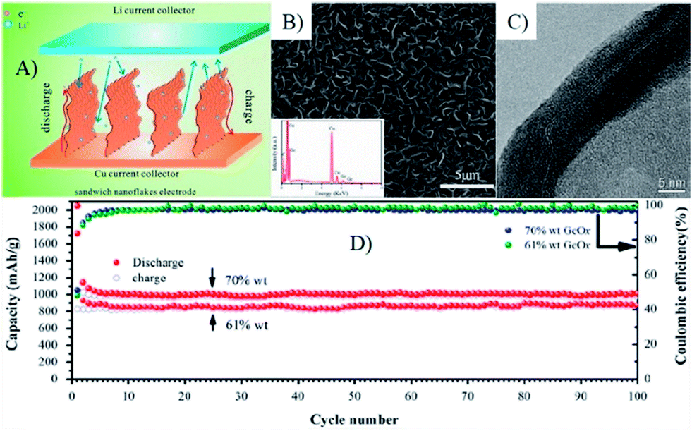 | ||
| Fig. 14 Scheme of the lithium ion diffusion mechanism in VAG@GeOx sandwich nanoflake based electrode (A), SEM (B) and TEM (C) image of the flake edge, clearly showing the sandwich structure of the VAG@GeOx composites. (D), cycling performance of the electrodes with different loads, 70 wt% and 61 wt%, both were tested at the rate of C/3. Inset in (B) shows the EDS result of post-deposition nanosheets.175 Reproduced from ref. 175, Copyright (2013) with permission from Elsevier. | ||
Introduction of holes into the planar sheet is also a good choice to improve the electrochemical performance of GNS sheets because the holes can provide a high density of cross plane diffusion channels for Li+ ions.101,106,138,160,241,244,245 Previous work indicated that holey graphene (HG) prepared by HNO3 (ref. 257)and KOH etching258 exhibited a significantly improved electrochemical performance as an anode material for LIBs, such as better cycle performance and higher rate capability in comparison with graphene sheets, activated graphene sheets, bare SnO2 and SnO2–GNSs composites.182
4 Beyond morphologies
4.1 Composition
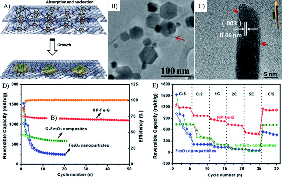
The composition of MOs also plays a significant role on the capacity, stability and rate performances of MOs–G nanocomposites. Firstly, most metal oxide anode materials are based on conversion reactions and alloy reactions. As a result, their theoretical capacities are tightly related with their compositions. For instance, Zn formed during conversion reactions can form alloys with Li, so ZnFe2O4 has a higher theoretical capacity of 1072 mA h g−1 than that of Fe3O4 (924 mA h g−1).259 But pure ZnFe2O4 has a reversible capacity of 957.7 mA h g−1, while its graphene composites can reach to 1082 mA h g−1.204 The search for other metal compounds with higher capacities is also a hot research topic. Metal carbonates, especially their graphene composites, can show higher capacities than their theoretical capacities.260–262 For example, CoCO3–graphene composites exhibited high capacities of over 1000 mA h g−1, because both of the cations (Co2+) and anions (CO32−) are involved in the electron transfer.263Recently, our research on MFe2O4–GNS (M = Mn,67 Co,69 Ni68) nanocomposites indicated that MFe2O4 could transform into the nanosized hybrid Fe3O4 (MOs) with the size of about 20 nm after the discharge–charge process (Fig. 15), and the in situ formed hybrid Fe3O4 (MOs) combined with GNSs to form a spongy porous structure, which could further accommodate its volume change and result in good stability of the electrode. Additionally, the formed hybrid could also act as a matrix of MOs (Fe3O4) to prevent the aggregation and growth of the in situ formed Fe3O4 (MOs) nanoparticles, and further lead to good cyclic stability.67 Various graphene composites with multiple MOs, including NiFe2O4–graphene heteroarchitectures,264 CoFe2O4/graphene sandwiched structures,265 ZnSnO3/graphene,266 hollow Zn2SnO4 boxes@graphene and the incorporation of In2O3 into SnO2,192,193 indicated that multiple MOs would improve the electrochemical activity and reduce the charge transfer resistance of electrodes, leading to an enhanced reversible capacity and rate capability. On the other hand, transferring the surface MOs to the corresponding high electron conductivity compounds, such as TiN,235 SnS2 (ref. 56, 57 and 267) or MoC,268 would also improve the rate capability of composites. Furthermore, the doping of N,97,121,269 F270 and boron271 could significantly increase the conductivity of graphene, and further lead to an enhanced reversible capacity and rate capability. For example, N-doped graphene–SnO2 sandwiched films had a capacity of 504 mA h g−1 at 5 A g−1, while the undoped graphene/SnO2 films only reached to 526 mA h g−1 at 0.1 A g−1 (Fig. 16).158,272
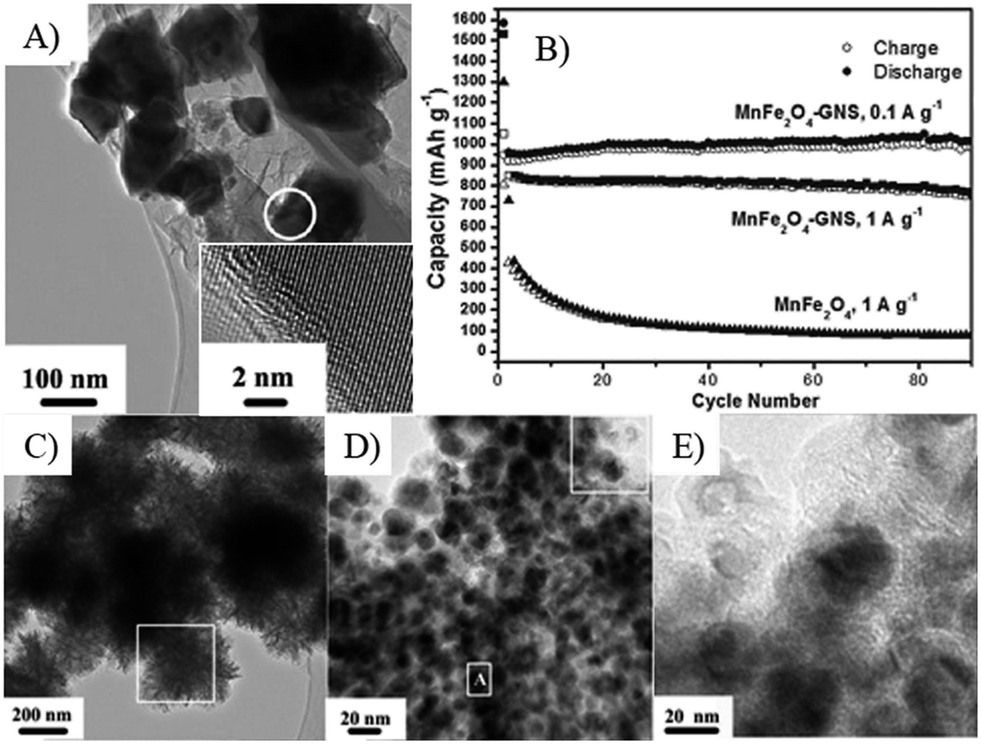 | ||
| Fig. 15 TEM image (A) and cyclic performances (B) of MnFe2O4–GNS composite. C–E, TEM image of MnFe2O4–GNSs nanocomposite after 70 charge–discharge process.67 Reproduced from ref. 67 with permission from The Royal Society of Chemistry. | ||
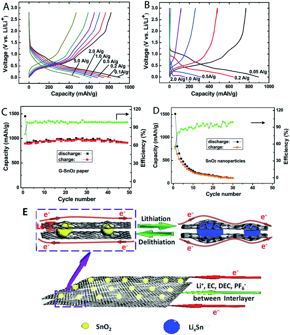 | ||
| Fig. 16 Charge/discharge curves of N-doped G–SnO2 papers (A) and commercial SnO2 nanoparticles (20–50 nm, (B) at various current densities. Cycling performance of N-doped G–SnO2 paper (C) and SnO2 nanoparticles (D) at a current density of 50 mA g−1. Schematic representation (E) showing paths for lithium-ions and electrons in the N-doped G–SnO2 paper, respectively.272 Reproduced with permission from ref. 272, Copyright (2012) WILEY-VCH. | ||
4.2 Interaction
Based on the above discussions, it can be found that the interactions between MOs nanomaterials and graphene greatly affect the stability and charge transfer resistance of anodes, which are tightly related to the electrochemical lithium storage performances (cyclic stability and rate capability). For example, hollow porous Fe3O4 bead–rGO composites showed higher electrochemical performances than that of the mechanically mixed composites due to the in situ formed strong interactions between the Fe3O4 beads and rGO.249 Graphene composites fabricated by co-assembly via electrostatic interactions also result in strong interactions between MOs nanomaterials and graphene, which can lead to composites in encapsulated and layered models with high mechanical and electrochemical stability and further reduce the charge transfer resistances.72,74–80,245Covalent bonds can be generated between MOs nanomaterials and graphene by in situ processes, in which the formation of nanomaterials and reduction of GO occur simultaneously.184,191,273,274 Detailed research and density functional theory (DFT) calculations clearly indicate that these bonds, usually with O or N atoms on the surface of graphene act as bridges, such as C–O–Ni,274 C–O–Fe,273 Sn–N–C and Sn–O–C191 bonds. With the C–O–Ni bond as an example (Fig. 17), composites with this bond showed a lower surface charge-transfer resistance (105.6 Ω) than the composite without bonding (213.3 Ω) or pure NiO nanosheets (279.9 Ω).274
 | ||
| Fig. 17 SEM (A) and TEM (B) images, capacity (C), interactions between graphene with oxygen functional groups and NiO (D), EIS spectra (E) and rate capability (F) of oxygen bridged NiO–graphene composites.274 Reproduced with permission from ref. 274, Copyright (2012) American Chemical Society. | ||
Furthermore, the rich functional groups on graphene can react with a cross-linking agent, such as benzene-1,4-diboronic acid (BDBA), to generate a graphene framework. The graphene framework can increase the overall electron conductivity, confine/fix nanoparticles and avoid their aggregations during the charge–discharge process (Fig. 18).111 A polymer coating on the composites can also increase structure stability, electrochemical activity and the interactions between oxides and graphene, and graphene composites with conductive polymers, such as polyaniline275,276 and PEDOT,277 have been invested and they showed remarkable rate performances. Even the un-conductive polymers, such as polydopamine, can also reduce the charge transfer resistances and further lead to stable high rate performances (Fig. 19).68 These polymer coated graphene composites can also be transformed to carbon coated graphene composites by the carbonization process, and the formed carbon shells tackle the deformation of the MOs nanoparticles, and keep the overall electrode highly conductive and active in lithium storage.278
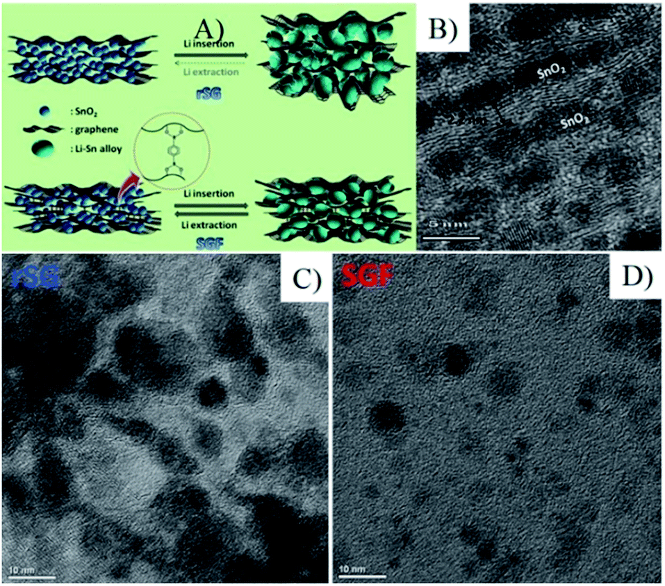 | ||
| Fig. 18 (A) Schematic diagram depicting the different behaviors between rSG and SGF during Li alloying/dealloying. (B) Ultramicrotomed cross-sectional view of SGF. HRTEM images of rSG (C) and SGF (D) after 50 cycles.111 Reproduced from ref. 111, Copyright (2013) with permission from Elsevier. | ||
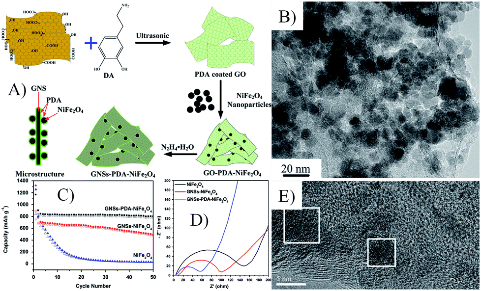 | ||
| Fig. 19 Schematic illustration of the possible formation mechanism (A), TEM image (B) and cyclic performances at 1 A g−1 (C), Nyquist plots (D) and TEM images after 50 cycles (E) of GNSs–PDA–NiFe2O4 nanocomposites.68 Reproduced from ref. 68, Copyright (2014) with permission from Elsevier. | ||
Gel mixtures of GO, metal precursors and carbon precursors have been widely used to prepare graphene composites. After being electrospun and carbonized, the obtained carbon coated graphene composites have unique lithium storage properties.135,213,279,280 Moreover, Ren et al. proved that the simultaneous formed carbon coating by the carbonization of glucose on the surface of the intermediate products (G–CrOOH) would provide more protection compared with the carbon layer post-formed by the carbonization of glucose on the surface of graphene–Cr2O3 composites. The simultaneously formed carbon layers could prevent the aggregation of Cr2O3 nanoparticles and limit their growth, whereas the latter could not effectively prevent the aggregation of nanoparticles because of mere coverage. As a result, the former carbon coated composites showed improved electrochemical properties compared to the latter composites, such as higher reversible capacity, better cycle performance and rate capability.131
5 Conclusions
We have reviewed the applications of 3D MOs–G composites in LIBs, especially on the effects of morphology and size of MOs or graphene on the properties of graphene composites. The core idea to improve the electrochemical performances of graphene composites in LIBs is how to enhance the electron conductivity and the lithium diffusion. Thus, MOs must have at least one dimension in the nanoscale to reduce the lithium diffusion distance. These nanomaterials also need to have enough contact sites and interactions with graphene, which will decide the charge transfer resistance, mechanical and electrochemical stability. Furthermore, proper pore size distribution is important for electrolyte access. To meet all of the above, one of the MOs or graphene must be in 3D structure. On the other hand, the composition of graphene composites and the interactions between graphene and MOs also affect their electrochemical performances.Although considerable research and breakthroughs have been achieved, the challenges of using graphene composites for lithium storage still remain. The fundamental question is the cost-effective, environmentally friend and sustainable approach to the large-scale production of high quality graphene or GO. At present, starting from graphite is still the most ideal route due to abundant reserves of graphite. In past years, it is believed that the physical exfoliation method is not suitable for mass production even though it can produce high quality graphene. However, good news came from Europe281 and China282 recently. Defect free graphene with few layers can be prepared on a large-scale by the high-shear mixing of graphite in suitable stabilizing liquids or using supercritical CO2 combined with the ultrasound approach.281,282 Second, graphene composite anodes always show a low initial efficiency and few of them can reach to 75%,163,167,228,273 which causes many issues in the full battery. The low initial efficiency is mainly derived from the formation of an SEI film on the surface of graphene composites with a large surface area and the side reactions of functional groups on graphene, thus high quality graphene is required and the surface area of the composites should be optimized. Third, the capacity of transition MOs–G composites usually increases with increasing cycles, and is always considerably higher than their initial and theoretical capacity, which is considered as the decomposition of the electrolyte catalyzed by MOs.68,81,204,243 This is also a very important problem for safety issues. The aim of final industrial implementation, large scale, low cost and simple production of graphene composites with high electrochemical lithium storage performances is one of the most important challenges. The road of realizing 3D MOs–graphene composites in LIBs is tortuous. However, with continued exploitations the future is bright!
Acknowledgements
The work was supported by the National Basic Research Program of China (2014CB239700), Shanghai Nano-Project (12nm0503502), Program of National Natural Science Foundation of China (21371121 and 21331004), Minhang District Developing Project, Science and Technology Commission of Shanghai Municipality (14DZ2250800).Notes and references
- L. Zhang, China's urban development report No.7, http://www.china.com.cn/opinion/think/2014-09/17/content_33532822.htm, accessed 17th September, 2014 Search PubMed.
- J. W. Kim, J. D. Ocon and D.-W. Park, et al., ChemSusChem, 2014, 7, 1265 CrossRef CAS PubMed.
- V. Chabot, D. Higgins and A. Yu, et al., Energy Environ. Sci., 2014, 7, 1564 CAS.
- C. Xu, B. Xu and Y. Gu, et al., Energy Environ. Sci., 2013, 6, 1388 CAS.
- D. Wei and J. Kivioja, Nanoscale, 2013, 5, 10108 RSC.
- L. W. Su, Y. Jing and Z. Zhou, Nanoscale, 2011, 3, 3967 RSC.
- B. Li, J. Zai and Y. Xiao, et al., CrystEngComm, 2014, 16, 3318 RSC.
- R. Yi, J. Zai and F. Dai, et al., Electrochem. Commun., 2013, 36, 29 CrossRef CAS PubMed.
- J. C. Shelton, H. R. Patil and J. M. Blakely, Surf. Sci., 1974, 43, 493 CrossRef CAS.
- C. Oshima and A. Nagashima, J. Phys.: Condens. Matter, 1997, 9, 1 CrossRef CAS.
- X. K. Lu, M. F. Yu and H. Huang, et al., Nanotechnology, 1999, 10, 269 CrossRef CAS.
- K. S. Novoselov, A. K. Geim and S. V. Morozov, et al., Science, 2004, 306, 666 CrossRef CAS PubMed.
- J. Zhu, M. Chen and Q. He, et al., RSC Adv., 2013, 3, 22790 RSC.
- Q. Xiang, J. Yu and M. Jaroniec, Chem. Soc. Rev., 2012, 41, 782 RSC.
- R. S. Edwards and K. S. Coleman, Acc. Chem. Res., 2013, 46, 23 CrossRef CAS PubMed.
- D. Chen, H. Feng and J. Li, Chem. Rev., 2012, 112, 6027 CrossRef CAS PubMed.
- Y. Sun and G. Shi, J. Polym. Sci., Part B: Polym. Phys., 2013, 51, 231 CrossRef CAS.
- A. Alarcon, N. Viet-Hung and S. Berrada, et al., IEEE T Electron Dev, 2013, 60, 985 CrossRef CAS.
- J. Cayssol, B. Huard and D. Goldhaber-Gordon, Phys. Rev. B: Condens. Matter Mater. Phys., 2009, 79, 075428 CrossRef.
- J. Liu, M. Durstock and L. Dai, Energy Environ. Sci., 2014, 7, 1297 CAS.
- P. Avouris, Proceedings 2010 10th IEEE International Conference on Nanotechnology and Joint Symposium with Nano Korea 2010 KINTEX (IEEE-NANO 2010), 2010, p. 6 Search PubMed.
- D. Gunlycke, D. A. Areshkin and J. Li, et al., Nano Lett., 2007, 7, 3608 CrossRef CAS PubMed.
- D. Yong-Joo and Y. Gyu-Chul, Nanotechnology, 2010, 21, 105204 CrossRef PubMed.
- R. Arsat, M. Breedon and M. Shafiei, et al., Chem. Phys. Lett., 2009, 467, 344 CrossRef CAS PubMed.
- H. Song, L. Zhang and C. He, et al., J. Mater. Chem., 2011, 21, 5972 RSC.
- T. Kuila, S. Bose and P. Khanra, et al., Biosens. Bioelectron., 2011, 26, 4637 CrossRef CAS PubMed.
- D. Zhao, Z. Li and L. Liu, et al., Acta Chim. Sin., 2014, 72, 185 CrossRef CAS.
- H. Jiang, Small, 2011, 7, 2413 CAS.
- P. V. Kamat, J. Phys. Chem. Lett., 2011, 2, 242 CrossRef CAS.
- S.-S. Yu and W.-T. Zheng, Nanoscale, 2010, 2, 1069 RSC.
- C. Huang, C. Li and G. Shi, Energy Environ. Sci., 2012, 5, 8848 CAS.
- L.-L. Tan, S.-P. Chai and A. R. Mohamed, ChemSusChem, 2012, 5, 1868 CrossRef CAS PubMed.
- H. Tian, S. Ma and H.-M. Zhao, et al., Nanoscale, 2013, 5, 8951 RSC.
- G. K. Dimitrakakis, E. Tylianakis and G. E. Froudakis, Nano Lett., 2008, 8, 3166 CrossRef CAS PubMed.
- S. Yang, L. Zhan and X. Xu, et al., Adv. Mater., 2013, 25, 2130 CrossRef CAS PubMed.
- L. Dai, Acc. Chem. Res., 2013, 46, 31 CrossRef CAS PubMed.
- S. Guo and S. Dong, Chem. Soc. Rev., 2011, 40, 2644 RSC.
- H. Gwon, H.-S. Kim and K. U. Lee, et al., Energy Environ. Sci., 2011, 4, 1277 CAS.
- H. Junbo, S. Yuyan and M. W. Ellis, et al., Phys. Chem. Chem. Phys., 2011, 13, 15384 RSC.
- T. Kuila, A. K. Mishra and P. Khanra, et al., Nanoscale, 2013, 5, 52 RSC.
- I. V. Lightcap and P. V. Kamat, Acc. Chem. Res., 2013, 46, 2235 CrossRef CAS PubMed.
- B. Luo, S. Liu and L. Zhi, Small, 2012, 8, 630 CrossRef CAS PubMed.
- M. Pumera, Energy Environ. Sci., 2011, 4, 668 CAS.
- D. Zhou, Y. Cui and B. Han, Chin. Sci. Bull., 2012, 57, 2983 CrossRef CAS.
- J. Liu, Y. Xue and M. Zhang, et al., Mrs Bull., 2012, 37, 1265 CrossRef CAS.
- Y. Sun, Q. Wu and G. Shi, Energy Environ. Sci., 2011, 4, 1113 CAS.
- L. Grande, V. T. Chundi and D. Wei, et al., Particuology, 2012, 10, 1 CrossRef CAS PubMed.
- X. Wan, Y. Huang and Y. Chen, Acc. Chem. Res., 2012, 45, 598 CrossRef CAS PubMed.
- Z.-S. Wu, G. Zhou and L.-C. Yin, et al., Nano Energy, 2012, 1, 107 CrossRef CAS PubMed.
- M. Xu, Y. Gao and X. Yang, et al., Chin. Sci. Bull., 2012, 57, 3000 CrossRef CAS.
- G. Zhao, T. Wen and C. Chen, et al., RSC Adv., 2012, 2, 9286 RSC.
- Q. Tang, Z. Zhou and Z. F. Chen, Nanoscale, 2013, 5, 4541 RSC.
- V. Z. Mordkovich, Synth. Met., 1996, 80, 243 CrossRef CAS.
- G. Wang, X. Shen and J. Yao, et al., Carbon, 2009, 47, 2049 CrossRef CAS PubMed.
- P. G. Bruce, B. Scrosati and J. M. Tarascon, Angew. Chem., Int. Ed., 2008, 47, 2930 CrossRef CAS PubMed.
- J. Zai, K. Wang and Y. Su, et al., J. Power Sources, 2011, 196, 3650 CrossRef CAS PubMed.
- J. Zai, X. Qian and K. Wang, et al., CrystEngComm, 2012, 14, 1364 RSC.
- Y. Li, Z.-Y. Fu and B.-L. Su, Adv. Funct. Mater., 2012, 22, 4634 CrossRef CAS.
- C. N. R. Rao, H. S. S. R. Matte and K. S. Subrahmanyam, Acc. Chem. Res., 2013, 46, 149 CrossRef CAS PubMed.
- S. Han, D. Wu and S. Li, et al., Small, 2013, 9, 1173 CrossRef CAS PubMed.
- V. Georgakilas, M. Otyepka and A. B. Bourlinos, et al., Chem. Rev., 2012, 112, 6156 CrossRef CAS PubMed.
- Y. Zhu, D. K. James and J. M. Tour, Adv. Mater., 2012, 24, 4924 CrossRef CAS PubMed.
- W. I. Park, C.-H. Lee and J. M. Lee, et al., Nanoscale, 2011, 3, 3522 RSC.
- X. Huang, X. Qi and F. Boey, et al., Chem. Soc. Rev., 2012, 41, 666 RSC.
- S.-M. Paek, E. Yoo and I. Honma, Nano Lett., 2009, 9, 72 CrossRef CAS PubMed.
- L. Tao, J. Zai and K. Wang, et al., RSC Adv., 2012, 2, 3410 RSC.
- Y. Xiao, J. Zai and L. Tao, et al., Phys. Chem. Chem. Phys., 2013, 15, 3939 RSC.
- Y. Xiao, J. Zai and X. Li, et al., Nano Energy, 2014, 6, 51 CrossRef CAS PubMed.
- Y. Xiao, X. Li and J. Zai, et al., Nano-Micro Lett., 2014 Search PubMed.
- A. K. Rai, L. T. Anh and J. Gim, et al., J. Power Sources, 2013, 244, 435 CrossRef CAS PubMed.
- Z. Chen, M. Zhou and Y. Cao, et al., Adv. Energy Mater., 2012, 2, 95 CrossRef CAS.
- X.-l. Huang, J. Chai and T. Jiang, et al., J. Mater. Chem., 2012, 22, 3404 RSC.
- H. Xiao-lei, W. Ru-zhi and X. Dan, et al., Adv. Funct. Mater., 2013, 23, 4345 CrossRef.
- S. Yang, X. Feng and S. Ivanovici, et al., Angew. Chem., Int. Ed., 2010, 49, 8408 CrossRef CAS PubMed.
- W. Wei, S. Yang and H. Zhou, et al., Adv. Mater., 2013, 25, 2909 CrossRef CAS PubMed.
- T. Yoon, J. Kim and J. Kim, et al., Energies, 2013, 6, 4830 CrossRef CAS PubMed.
- Y. Luo, J. Luo and W. Zhou, et al., J. Mater. Chem. A, 2013, 1, 273 CAS.
- R. Yi, J. Zai and F. Dai, et al., Nano Energy, 2014, 6, 211 CrossRef CAS PubMed.
- X. Yang, K. Fan and Y. Zhu, et al., ACS Appl. Mater. Interfaces, 2013, 5, 997 CAS.
- S. J. R. Prabakar, Y.-H. Hwang and E.-G. Bae, et al., Adv. Mater., 2013, 25, 3307 CrossRef CAS PubMed.
- Z.-S. Wu, W. Ren and L. Wen, et al., ACS Nano, 2010, 4, 3187 CrossRef CAS PubMed.
- L. Tao, J. Zai and K. Wang, et al., J. Power Sources, 2012, 202, 230 CrossRef CAS PubMed.
- Y.-J. Hu, J. Jin and H. Zhang, et al., Acta Phys.-Chim. Sin., 2010, 26, 2073 CAS.
- P. Lue, Y. Feng and X. Zhang, et al., Sci. China: Technol. Sci., 2010, 53, 2311 CrossRef PubMed.
- J. N. Coleman, Acc. Chem. Res., 2013, 46, 14 CrossRef CAS PubMed.
- D. Wang, D. Choi and J. Li, et al., ACS Nano, 2009, 3, 907 CrossRef CAS PubMed.
- D. Wang, R. Kou and D. Choi, et al., ACS Nano, 2010, 4, 1587 CrossRef CAS PubMed.
- L. Pan, H. Zhao and W. Shen, et al., J. Mater. Chem. A, 2013, 1, 7159 CAS.
- Y. Chen, B. Song and L. Lu, et al., Nanoscale, 2013, 5, 6797 RSC.
- Q. Han, J. Zai and Y. Xiao, et al., RSC Adv., 2013, 3, 20573 RSC.
- Y. Sheng, Y. Wenbo and Z. Jia, et al., Adv. Funct. Mater., 2013, 23, 91 CrossRef.
- S. X. Yu, L. W. Yang and Y. Tian, et al., J. Mater. Chem. A, 2013, 1, 12750 CAS.
- Z. Zhang, Y. Wang and D. Li, et al., Ind. Eng. Chem. Res., 2013, 52, 14906 CrossRef CAS.
- H. Sun, X. Sun and T. Hu, et al., J. Phys. Chem. C, 2014, 118, 2263 CAS.
- J. Zhang, S. Wan and B. Yan, et al., J. Nanosci. Nanotechnol., 2013, 13, 4364 CrossRef CAS PubMed.
- S. Bai, S. Chen and X. Shen, et al., RSC Adv., 2012, 2, 10977 RSC.
- F. Zou, X. Hu and Y. Sun, et al., Chem–Eur. J., 2013, 19, 6027 CrossRef CAS PubMed.
- X. Chaohe, S. Jing and G. Lian, Nanoscale, 2012, 4, 5425 RSC.
- X. Chaohe, S. Jing and G. Lian, J. Mater. Chem., 2012, 22, 975 RSC.
- M. Yu, H. Sun and X. Sun, et al., Mater. Lett., 2013, 108, 29 CrossRef CAS PubMed.
- Y. Zhang, H. Liu and Z. Zhu, et al., Electrochim. Acta, 2013, 108, 465 CrossRef CAS PubMed.
- J. Wang, Y. Zhou and B. Xiong, et al., Electrochim. Acta, 2013, 88, 847 CrossRef CAS PubMed.
- Y. Chen, M. Zhuo and J. Deng, et al., J. Mater. Chem. A, 2014, 2, 4449 CAS.
- H. Huang, J. Fang and Y. Xia, et al., J. Mater. Chem. A, 2013, 1, 2495 CAS.
- Y. Dong, S. Li and H. Xu, et al., Phys. Chem. Chem. Phys., 2013, 15, 17165 RSC.
- S. Yongming, H. Xianluo and L. Wei, et al., Adv. Funct. Mater., 2013, 23, 2436 CrossRef.
- Z. Zhang, Q. Chu and H. Li, et al., J. Colloid Interface Sci., 2013, 409, 38 CrossRef CAS PubMed.
- S. Yaodong, C. Jun Song and Z. Jixin, et al., J. Nanopart. Res., 2013, 15, 1913 CrossRef.
- W. Bao, W. Xing-Long and S. Chun-Ying, et al., J. Mater. Chem., 2010, 20, 10661 RSC.
- L. Q. Lu and Y. Wang, Electrochem. Commun., 2012, 14, 82 CrossRef CAS PubMed.
- H. Yun-Hwa, B. Eun Gyoung and S. Kee-Sun, et al., J. Power Sources, 2013, 240, 683 CrossRef PubMed.
- G. Qi, Z. Zhe and G. Hailing, et al., J. Power Sources, 2013, 240, 149 CrossRef PubMed.
- B. Zhao, G. Zhang and J. Song, et al., Electrochim. Acta, 2011, 56, 7340 CrossRef CAS PubMed.
- J. Zhu, T. Zhu and X. Zhou, et al., Nanoscale, 2011, 3, 1084 RSC.
- Z. Ming, Q. Baihua and D. Lei, et al., J. Mater. Chem., 2012, 22, 3868 RSC.
- S.-K. Park, S.-H. Yu and N. Pinna, et al., J. Mater. Chem., 2012, 22, 2520 RSC.
- S. Yang, Y. Gong and Z. Liu, et al., Nano Lett., 2013, 13, 1596 CAS.
- J. Shuhua, Y. Wenbo and G. Ziqi, et al., J. Mater. Sci., 2013, 48, 3870 CrossRef.
- J. Qu, Y. Yan and Y.-X. Yin, et al., ACS Appl. Mater. Interfaces, 2013, 5, 5777 CAS.
- D. W.-P. Pang, F.-W. Yuan and Y.-C. Chang, et al., Nanoscale, 2012, 4, 4562 RSC.
- S.-K. Park, A. Jin and S.-H. Yu, et al., Electrochim. Acta, 2014, 120, 452 CrossRef CAS PubMed.
- X. Chi, L. Chang and D. Xie, et al., Mater. Lett., 2013, 106, 178 CrossRef CAS PubMed.
- L. Noerochim, J.-Z. Wang and D. Wexler, et al., J. Power Sources, 2013, 228, 198 CrossRef CAS PubMed.
- F. Xiao-Yong, S. Xiao-Yuan and W. Jing, et al., J. Solid State Electrochem., 2013, 17, 201 CrossRef PubMed.
- C. Nethravathi, B. Viswanath and J. Michael, et al., Carbon, 2012, 50, 4839 CrossRef CAS PubMed.
- L. Tian, Q. Zhuang and J. Li, et al., Electrochim. Acta, 2012, 65, 153 CrossRef CAS PubMed.
- J. Qu, Y.-X. Yin and Y.-Q. Wang, et al., ACS Appl. Mater. Interfaces, 2013, 5, 3932 CAS.
- P. Lian, J. Wang and D. Cai, et al., Electrochim. Acta, 2014, 116, 103 CrossRef CAS PubMed.
- Y. Zhu, C. Li and C. Cao, RSC Adv., 2013, 3, 11860 RSC.
- M. Zhang, M. Jia and Y. Jin, et al., J. Alloys Compd., 2013, 566, 131 CrossRef CAS PubMed.
- W. Yue, S. Tao and J. Fu, et al., Carbon, 2013, 65, 97 CrossRef CAS PubMed.
- D. Qiu, L. Ma and M. Zheng, et al., Mater. Lett., 2012, 84, 9 CrossRef CAS PubMed.
- D. Yucheng, M. Ruguang and H. Mingjun, et al., Phys. Chem. Chem. Phys., 2013, 15, 7174 RSC.
- Y. Jiang, T. Yuan and W. Sun, et al., ACS Appl. Mater. Interfaces, 2012, 4, 6216 CAS.
- J. Zhu, G. Zhang and X. Yu, et al., Nano Energy, 2014, 3, 80 CrossRef CAS PubMed.
- Z. Jian, L. Danni and Z. Guanhua, et al., Nanoscale, 2013, 5, 5499 RSC.
- M. Zhang, D. Lei and X. Yin, et al., J. Mater. Chem., 2010, 20, 5538 RSC.
- S. Q. Chen and Y. Wang, J. Mater. Chem., 2010, 20, 9735 RSC.
- X. Zhu, Y. Zhu and S. Murali, et al., ACS Nano, 2011, 5, 3333 CrossRef CAS PubMed.
- S.-H. Yu, D. E. Conte and S. Baek, et al., Adv. Funct. Mater., 2013, 23, 4293 CrossRef CAS.
- C. Zhong, J. Wang and Z. Chen, et al., J. Phys. Chem. C, 2011, 115, 25115 CAS.
- T. Chen, L. Pan and X. Liu, et al., RSC Adv., 2012, 2, 11719 RSC.
- L. Li, Z. Guo and A. Du, et al., J. Mater. Chem., 2012, 22, 3600 RSC.
- N. Li, Y. Xiao and C. Hu, et al., Chem–Asian J., 2013, 8, 1960 CrossRef CAS PubMed.
- J. W. Ko, S.-W. Kim and J. Hong, et al., Green Chem., 2012, 14, 2391 RSC.
- J. Qiu, P. Zhang and M. Ling, et al., ACS Appl. Mater. Interfaces, 2012, 4, 3636 CAS.
- K. Gil-Pyo, N. Inho and K. Nam Dong, et al., Electrochem. Commun., 2012, 22, 93 CrossRef PubMed.
- X. Meng, D. Geng and J. Liu, et al., Nanotechnology, 2011, 22, 165602 CrossRef PubMed.
- E. B. Nursanto, A. Nugroho and S.-A. Hong, et al., Green Chem., 2011, 13, 2714 RSC.
- L. Zhuo, Y. Wu and W. Zhou, et al., ACS Appl. Mater. Interfaces, 2013, 5, 7065 CAS.
- L. Zhuo, Y. Wu and L. Wang, et al., J. Mater. Chem. A, 2013, 1, 3954 CAS.
- A. K. Rai, J. Gim and A. Ly Tuan, et al., Electrochim. Acta, 2013, 100, 63 CrossRef CAS PubMed.
- D. Li, D. Shi and Z. Chen, et al., RSC Adv., 2013, 3, 5003 RSC.
- J. Xiao, G. Xu and S.-G. Sun, et al., Part. Part. Syst. Charact., 2013, 30, 893 CrossRef CAS.
- Y. Qi, H. Zhang and N. Du, et al., J. Mater. Chem. A, 2013, 1, 2337 CAS.
- H. Xin, C. Jing and Y. Hong, et al., J. Mater. Chem. A, 2013, 1, 6901 Search PubMed.
- Y. Sun, X. Hu and W. Luo, et al., J. Mater. Chem. A, 2013, 1, 4468 CAS.
- G. Xia, N. Li and D. Li, et al., ACS Appl. Mater. Interfaces, 2013, 5, 8607 CAS.
- G. Wang, H. Wang and S. Cai, et al., J. Power Sources, 2013, 239, 37 CrossRef CAS PubMed.
- L. Li, G. Zhou and Z. Weng, et al., Carbon, 2014, 67, 500 CrossRef CAS PubMed.
- G.-W. Zhou, J. Wang and P. Gao, et al., Ind. Eng. Chem. Res., 2013, 52, 1197 CrossRef CAS.
- C. Zhao, S.-L. Chou and Y. Wang, et al., RSC Adv., 2013, 3, 16597 RSC.
- W. Xiao, Z. Wang and H. Guo, et al., Appl. Surf. Sci., 2013, 266, 148 CrossRef CAS PubMed.
- L. Xiao, D. Wu and S. Han, et al., ACS Appl. Mater. Interfaces, 2013, 5, 3764 CAS.
- D. Meng, X. Chaohe and S. Jing, et al., J. Mater. Chem. A, 2013, 1, 7154 Search PubMed.
- B. Jang, O. B. Chae and S.-K. Park, et al., J. Mater. Chem. A, 2013, 1, 15442 CAS.
- D. Chen, H. Quan and J. Liang, et al., Nanoscale, 2013, 5, 9684 RSC.
- X. Huang, B. Sun and S. Chen, et al., Chem–Asian J., 2014, 9, 206 CrossRef CAS PubMed.
- M. Cai, H. Qian and Z. Wei, et al., RSC Adv., 2014, 4, 6379 RSC.
- M. Zhang and M. Jia, J. Alloys Compd., 2013, 551, 53 CrossRef CAS PubMed.
- A. Hu, X. Chen and Y. Tang, et al., Mater. Lett., 2013, 91, 315 CrossRef CAS PubMed.
- Y. Chang, J. Li and B. Wang, et al., J. Mater. Chem. A, 2013, 1, 14658 CAS.
- Y. Sun, X. Hu and W. Luo, et al., ACS Appl. Mater. Interfaces, 2013, 5, 10145 CAS.
- W. Yue, S. Jiang and W. Huang, et al., J. Mater. Chem. A, 2013, 1, 6928 CAS.
- S. Jin, N. Li and H. Cui, et al., Nano Energy, 2013, 2, 1128 CrossRef CAS PubMed.
- S. Wu, Y. Zhu and C. Li, et al., J. Alloys Compd., 2014, 582, 289 CrossRef CAS PubMed.
- Z. Xiaoyi, L. Jianjiang and S. Xilin, et al., Adv. Mater. Res., 2013, 709, 157 CrossRef.
- Y. Chen, X. Di and C. Ma, et al., RSC Adv., 2013, 3, 17659 RSC.
- D. Zhou, H. Wu and Z. Wei, et al., Phys. Chem. Chem. Phys., 2013, 15, 16898 RSC.
- G.-P. Kim, I. Nam and S. Park, et al., Nanotechnology, 2013, 24 Search PubMed.
- C. Jianli, X. Huolin and Z. Haimei, et al., J. Power Sources, 2013, 232, 152 CrossRef PubMed.
- Y. Yang, X. Ji and F. Lu, et al., Phys. Chem. Chem. Phys., 2013, 15, 15098 RSC.
- B. P. Vinayan and S. Ramaprabhu, J. Mater. Chem. A, 2013, 1, 3865 CAS.
- H. Song, N. Li and H. Cui, et al., J. Mater. Chem. A, 2013, 1, 7558 CAS.
- J. Lin, Z. Peng and C. Xiang, et al., ACS Nano, 2013, 7, 6001 CrossRef CAS PubMed.
- J. Liang, Y. Liu and L. Guo, et al., RSC Adv., 2013, 3, 11489 RSC.
- Z. Junsheng, W. Dianlong and W. Lin, Ionics, 2013, 19, 1223 CrossRef.
- Y. Huang, D. Wu and S. Han, et al., ChemSusChem, 2013, 6, 1510 CrossRef CAS PubMed.
- Q. Guo and X. Qin, ECS Solid State Lett., 2013, 2, M41 CrossRef CAS PubMed.
- C. Gu, H. Zhang and X. Wang, et al., Mater. Res. Bull., 2013, 48, 4112 CrossRef CAS PubMed.
- X. Zhou, L.-J. Wan and Y.-G. Guo, Adv. Mater., 2013, 25, 2152 CrossRef CAS PubMed.
- H. Yang, T. Song and S. Lee, et al., Electrochim. Acta, 2013, 91, 275 CrossRef CAS PubMed.
- W. Xing, X. Wang and L. Song, et al., Mater. Chem. Phys., 2013, 140, 441 CrossRef CAS PubMed.
- R. Huang, H. Ge and X. Lin, et al., RSC Adv., 2013, 3, 1235 RSC.
- M. Zhen, L. Su and Z. Yuan, et al., RSC Adv., 2013, 3, 13696 RSC.
- H. Tao, S. Xiang and S. Hongtao, et al., Carbon, 2013, 51, 322 CrossRef PubMed.
- D. Li, D. Shi and Z. Liu, et al., J. Nanopart. Res., 2013, 15 Search PubMed.
- C. Dandan, L. Dongdong and W. Suqing, et al., J. Alloys Compd., 2013, 561, 54 CrossRef PubMed.
- C. Ban, M. Xie and X. Sun, et al., Nanotechnology, 2013, 24 Search PubMed.
- X. Jiang, X. Yang and Y. Zhu, et al., New J. Chem., 2013, 37, 3671 RSC.
- C. Han, M. Yan and L. Mai, et al., Nano Energy, 2013, 2, 916 CrossRef CAS PubMed.
- H. Zhao, L. Pan and S. Xing, et al., J. Power Sources, 2013, 222, 21 CrossRef CAS PubMed.
- W. Song, J. Xie and W. Hu, et al., J. Power Sources, 2013, 229, 6 CrossRef CAS PubMed.
- H. Xia, Y. Qian and Y. Fu, et al., Solid State Sci., 2013, 17, 67 CrossRef CAS PubMed.
- X. Sun, C. Zhou and M. Xie, et al., J. Mater. Chem. A, 2014, 2, 7319 CAS.
- L. Zhang, Z. Wang and L. Wang, et al., Mater. Lett., 2013, 108, 9 CrossRef CAS PubMed.
- Z. Chen, Y. Yan and S. Xin, et al., J. Mater. Chem. A, 2013, 1, 11404 CAS.
- R. Wang, C. Xu and J. Sun, et al., J. Mater. Chem. A, 2013, 1, 1794 CAS.
- A. Hu, X. Chen and Y. Tang, et al., Electrochem. Commun., 2013, 28, 139 CrossRef CAS PubMed.
- Y. Chen, C. Yan and O. G. Schmidt, Adv. Energy Mater., 2013, 3, 1269 CrossRef CAS.
- F. Tu, T. Wu and S. Liu, et al., Electrochim. Acta, 2013, 106, 406 CrossRef CAS PubMed.
- J. G. Radich, Y.-S. Chen and P. V. Kamat, ECS J. Solid State Sci. Technol., 2013, 2, M3178 CrossRef CAS PubMed.
- J. Zhu, D. Lei and G. Zhang, et al., Nanoscale, 2013, 5, 5499 RSC.
- D. Wang, J. Yang and X. Li, et al., Energy Environ. Sci., 2013, 6, 2900 CAS.
- H. Juan, W. Rong and Z. Pengjun, et al., Mater. Lett., 2013, 100, 173 CrossRef PubMed.
- H. Juan, W. Rong and Z. Pengjun, et al., Integr. Ferroelectr., 2013, 144, 66 CrossRef.
- F. Zou, X. Hu and L. Qie, et al., Nanoscale, 2014, 6, 924 RSC.
- Y. Li, Y. Wang and Y. Zhang, Sci. Adv. Mater., 2013, 5, 523 CrossRef CAS PubMed.
- Y. Liu, W. Wang and L. Gu, et al., ACS Appl. Mater. Interfaces, 2013, 5, 9850 CAS.
- S. Chen, P. Bao and G. Wan, Nano Energy, 2013, 2, 425 CrossRef CAS PubMed.
- X. Wang, W. Tian and D. Liu, et al., Nano Energy, 2013, 2, 257 CrossRef CAS PubMed.
- H. Liu, J. Huang and C. Xiang, et al., J. Mater. Sci.: Mater. Electron., 2013, 24, 3640 CrossRef CAS PubMed.
- N. Li, G. Zhou and R. Fang, et al., Nanoscale, 2013, 5, 7780 RSC.
- Y. Tang, D. Wu and S. Chen, et al., Energy Environ. Sci., 2013, 6, 2447 CAS.
- J. Cheng, B. Wang and H. L. Xin, et al., J. Mater. Chem. A, 2013, 1, 10814 CAS.
- C. Nethravathi, C. R. Rajamathi and M. Rajamathi, et al., ACS Appl. Mater. Interfaces, 2013, 5, 2708 CAS.
- X. Cao, B. Zheng and X. Rui, et al., Angew. Chem., Int. Ed., 2014, 53, 1404 CrossRef CAS PubMed.
- Q. Zhou, Z. Zhao and Z. Wang, et al., Nanoscale, 2014, 6, 2286 RSC.
- J. Zhu, D. Yang and X. Rui, et al., Small, 2013, 9, 3390 CrossRef CAS PubMed.
- S. Tao, W. Yue and M. Zhong, et al., ACS Appl. Mater. Interfaces, 2014, 6, 6332 CAS.
- L. Zhao, W. Yue and Y. Ren, Electrochim. Acta, 2014, 116, 31 CrossRef CAS PubMed.
- G. Ji, B. Ding and Z. Sha, et al., Nanoscale, 2013, 5, 5965 RSC.
- Y. Zhao, Y. Huang and W. Zhang, et al., RSC Adv., 2013, 3, 23489 RSC.
- C. Xu, X. Wang and L. Yang, et al., J. Solid State Chem., 2009, 182, 2486 CrossRef CAS PubMed.
- Y. Qiu, K. Yan and S. Yang, et al., ACS Nano, 2010, 4, 6515 CrossRef CAS PubMed.
- Y. Xia, P. Yang and Y. Sun, et al., Adv. Mater., 2003, 15, 353 CrossRef CAS.
- M. Kwiat, S. Cohen and A. Pevzner, et al., Nano Today, 2013, 8, 677 CrossRef CAS PubMed.
- Z. L. Wang, Adv. Mater., 2000, 12, 1295 CrossRef CAS.
- Y. Zou, J. Kan and Y. Wang, J. Phys. Chem. C, 2011, 115, 20747 CAS.
- A. Yu, H. W. Park and A. Davies, et al., J. Phys. Chem. Lett., 2011, 2, 1855 CrossRef CAS.
- Z. Yuqin and W. Yong, Nanoscale, 2011, 3, 2615 RSC.
- Y.-S. He, D.-W. Bai and X. Yang, et al., Electrochem. Commun., 2010, 12, 570 CrossRef CAS PubMed.
- H. Xia, D. Zhu and Y. Fu, et al., Electrochim. Acta, 2012, 83, 166 CrossRef CAS PubMed.
- J. Zai, C. Yu and L. Tao, et al., CrystEngComm, 2013, 15, 6663 RSC.
- H. Yun, H. Xiao-lei and L. Jian-she, et al., J. Mater. Chem., 2012, 22, 2844 RSC.
- K. Haegyeom, K. Sung-Wook and P. Young-Uk, et al., Nano Res., 2010, 3, 813 CrossRef PubMed.
- X. Rui, J. Zhu and D. Sim, et al., Nanoscale, 2011, 3, 4752 RSC.
- Q. Zou, J.-T. Zai and P. Liu, et al., Chem. Res. Chin. Univ., 2011, 32, 630 CAS.
- Y. Chen, B. Song and X. Tang, et al., J. Mater. Chem., 2012, 22, 17656 RSC.
- C. Huagiang, L. Baojun and Z. Jingxian, et al., J. Mater. Chem., 2012, 22, 9759 RSC.
- L. Na, L. Gang and Z. Chao, et al., Adv. Funct. Mater., 2011, 21, 1717 CrossRef.
- Y. Wenbo, L. Zhenzhen and J. Shuhua, et al., J. Mater. Chem., 2012, 22, 16318 RSC.
- X. Yang, K. Fan and Y. Zhu, et al., J. Mater. Chem., 2012, 22, 17278 RSC.
- B. G. Choi, S.-J. Chang and Y. B. Lee, et al., Nanoscale, 2012, 4, 5924 RSC.
- X. Zhu, G. Ning and X. Ma, et al., J. Mater. Chem. A, 2013, 1, 14023 CAS.
- J. Zai, C. Yu and Q. Zou, et al., RSC Adv., 2012, 2, 4397 RSC.
- X. Zhao, C. M. Hayner and M. C. Kung, et al., ACS Nano, 2011, 5, 8739 CrossRef CAS PubMed.
- J. Zhongging, P. Bo and A. Manthiram, J. Mater. Chem. A, 2013, 1, 7775 Search PubMed.
- Y. Ding, Y. F. Yang and H. X. Shao, Electrochim. Acta, 2011, 56, 9433 CrossRef CAS PubMed.
- S. Mirhashemihaghighi, B. Leon and C. P. Vicente, et al., Inorg. Chem., 2012, 51, 5554 CrossRef CAS PubMed.
- M. J. Aragon, C. Perez-Vicente and J. L. Tirado, Electrochem. Commun., 2007, 9, 1744 CrossRef CAS PubMed.
- M. J. Aragon, B. Leon and C. P. Vicente, et al., J. Power Sources, 2011, 196, 2863 CrossRef CAS PubMed.
- L. W. Su, Z. Zhou and X. Qin, et al., Nano Energy, 2013, 2, 276 CrossRef CAS PubMed.
- Y. Fu, Y. Wan and H. Xia, et al., J. Power Sources, 2012, 213, 338 CrossRef CAS PubMed.
- S. Liu, J. Xie and C. Fang, et al., J. Mater. Chem., 2012, 22, 19738 RSC.
- W. Song, J. Xie and S. Liu, et al., J. Mater. Res., 2012, 27, 3096 CrossRef CAS.
- J. Zhu, D. Wang and L. Wang, et al., Electrochim. Acta, 2013, 91, 323 CrossRef CAS PubMed.
- H.-J. Zhang, K.-X. Wang and X.-Y. Wu, et al., Adv. Funct. Mater., 2014, 24, 3399 CrossRef CAS.
- A. L. M. Reddy, A. Srivastava and S. R. Gowda, et al., ACS Nano, 2010, 4, 6337 CrossRef CAS PubMed.
- H. Tachikawa, T. Iyama and H. Kawabata, Jpn. J. Appl. Phys., 2010, 49, 01ah02 Search PubMed.
- X. Wang, Z. Zeng and H. Ahn, et al., Appl. Phys. Lett., 2009, 95, 183103 CrossRef PubMed.
- X. Wang, X. Cao and L. Bourgeois, et al., Adv. Funct. Mater., 2012, 22, 2682 CrossRef CAS.
- M. Zheng, D. Qiu and B. Zhao, et al., RSC Adv., 2013, 3, 699 RSC.
- G. Zhou, D.-W. Wang and L.-C. Yin, et al., ACS Nano, 2012, 6, 3214 CrossRef CAS PubMed.
- L. Renlong, C. Huaqiang and Q. Dong, et al., J. Mater. Chem., 2011, 21, 17654 RSC.
- F. Zhang, H. Cao and D. Yue, et al., Inorg. Chem., 2012, 51, 9544 CrossRef CAS PubMed.
- W. Wang, W. Lei and T. Yao, et al., Electrochim. Acta, 2013, 108, 118 CrossRef CAS PubMed.
- Y. Su, S. Li and D. Wu, et al., ACS Nano, 2012, 6, 8349 CrossRef CAS PubMed.
- C. Zhang, X. Peng and Z. Guo, et al., Carbon, 2012, 50, 1897 CrossRef CAS PubMed.
- X. Zhang, P. S. Kumar and V. Aravindan, et al., J. Phys. Chem. C, 2012, 116, 14780 CAS.
- K. R. Paton, E. Varrla and C. Backes, et al., Nat. Mater., 2014, 13, 624630 CrossRef PubMed.
- Y. Gao, W. Shi and W. Wang, et al., Ind. Eng. Chem. Res., 2014, 53, 2839 CrossRef CAS.
| This journal is © The Royal Society of Chemistry 2015 |