Room-temperature high-performance acetone gas sensor based on hydrothermal synthesized SnO2-reduced graphene oxide hybrid composite
Dongzhi Zhang*,
Aiming Liu,
Hongyan Chang and
Bokai Xia
College of Information and Control Engineering, China University of Petroleum (East China), Qingdao 266580, People’s Republic of China. E-mail: dzzhang@upc.edu.cn; Fax: +86-532-86981335; Tel: +86-532-86981813 ext. 426
First published on 27th November 2014
Abstract
In this paper, we demonstrated a room-temperature acetone gas sensor based on a tin dioxide (SnO2)-reduced graphene oxide (RGO) hybrid composite film. The SnO2–RGO composite film sensor was fabricated on a PCB substrate with rectangular-ambulatory-plane interdigitated microelectrodes by using a facile hydrothermal method. The presence of small SnO2 nanoparticles on RGO sheets was characterized by SEM, XRD and BET measurements, demonstrating good structures without irreversible restacking of sheets and agglomeration. The sensing properties of the SnO2–RGO hybrid film sensor were investigated by exposing it to various concentrations of acetone gas at room temperature. It was found that the presented sensor exhibited not only an excellent response to acetone gas, but also a fast response–recovery time and good repeatability, exhibiting the unique advantages of the SnO2–RGO hybrid composite as a building block for sensor fabrication. The gas response of the SnO2–RGO hybrid composite was about 2-fold higher than that of the pure RGO film, and the possible sensing mechanism was mainly attributed to the high surface area, three-dimensional porous nanostructure and special interactions between the RGO sheets and SnO2 nanoparticles.
1. Introduction
Diagnostic sensing devices using the exhaled breath of humans have critical advantages due to noninvasive diagnosis and a high potential for portable devices with simple analysis processes. Sensitive detection of acetone gas in exhaled human breath, serving as a breath marker for some diseases such as diabetes and halitosis, may offer a valuable reference for the early diagnosis of these diseases.1–5 Furthermore, the detection of acetone gas is also of great significance in various other applications, such as industrial production, environmental monitoring, and the forecast of toxic gas or volatile poisonous chemical leakage. Until now, many efforts have been devoted to developing acetone gas sensors using various sensing materials, such as polymers,6,7 ceramics,8,9 metal oxide semiconductors,10–14 and carbon nanotube-based composites,15–17 but they suffer from specific drawbacks such as high-cost, step complexity and being time consuming, limiting their wider applications.As emerging 2D nanomaterials, graphene and reduced graphene oxide have attracted extensive attention due to the large specific surface area of 2600 m2 g−1 for molecular adsorption, high chemical stability, and exceptional electrical properties such as low noise level and high carrier mobility.18–22 Up to now, some investigations have reported the promising performance of graphene-based gas sensors, but have been limited to several sensitive gas species such as NO2, NH3, NO and CO2.23–29 Recent advances demonstrating the incorporation of graphene with metal oxide nanoparticles have attracted much attention for the construction of high-performance acetone gas sensors.30,31 Liu et al. prepared a graphene–ZnFe2O4 composite via a solvothermal method for acetone gas sensing, and revealed that the mixing of graphene with ZnFe2O4 can lower the operating temperature of the sensors to acetone vapor.30 Choi et al. reported a WO3 hemitube nanostructure modification with graphene-based materials for the detection of acetone. A rapid response and superior sensitivity were observed at 300 °C.31 Although some investigations have reported great potential for metal oxide–graphene composites, some specific problems have hindered their applications, such as high operation temperatures, and produce challenging obstacles for achieving low power consumption towards practical applications.
In this work, a room-temperature acetone gas sensor based on a tin dioxide (SnO2)-reduced graphene oxide (RGO) hybrid composite film is demonstrated. The SnO2–RGO composite film sensor was fabricated on a PCB substrate with interdigitated microelectrodes by using a facile hydrothermal method. The attachment of SnO2 nanoparticles on RGO sheets was investigated by using SEM, XRD and BET, demonstrating good structures without irreversible restacking of sheets and agglomeration. The sensing properties of the SnO2–RGO hybrid film sensor were investigated by exposing it to various concentrations of acetone gas at room temperature. It was found that the as-prepared SnO2–RGO hybrid composite is significant for practical applications for monitoring acetone gas. Lastly, a possible sensing mechanism of the proposed sensor is discussed in detail.
2. Experiment
2.1 Materials
Commercially available high purity reduced graphene oxide (RGO) nanosheets (>99%) were obtained from Chengdu Organic Chemical Co. Ltd (Chengdu, China). SnCl4·5H2O (99%) was purchased from Shanghai Hansi Chemical Industry Co., Ltd (Shanghai, China). All the above chemicals were used as received without further treatment.2.2 Preparation of the SnO2–RGO hybrid composite
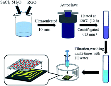
The SnO2–RGO hybrid composite was synthesized by using a facile hydrothermal treatment of SnCl4 solution in the presence of RGO.32,33 A schematic illustration for the preparation of the SnO2–RGO hybrid composite is shown in Fig. 1. In a typical synthesis process, 24 mg SnCl4·5H2O and 1.5 mL of RGO (0.5 mg mL−1) were added into 20 mL of deionized (DI) water with stirring for 1 h. Then, the aqueous dispersion was transferred into a 40 mL Teflon-lined, stainless-steel autoclave and was heated at 120 °C for 12 h. Afterwards, when the autoclave had cooled down to room temperature, the products were obtained by centrifugation at 3000 rpm for 15 min, and subsequently washed with DI water several times for the purpose of removing excess chloride ions. The resulting products were dispersed in DI water for characterization and further use.2.3 Sensor fabrication
The SnO2–RGO nanocomposite sensor was fabricated on a printed circuit board (PCB) substrate by using microfabrication technology. A pair of rectangular-ambulatory-plane interdigitated electrodes (RAP-IDEs) were deposited on the PCB substrate via photolithographic technology. The outline dimensions of the PCB-RAP-IDE were 10 mm × 10 mm, the electrode thickness was 50 μm and the width and gap were both 200 μm. The sensing film of the SnO2–RGO nanocomposite was prepared by using a drop-casting method. In brief, the resulting SnO2–RGO dispersion was dropped onto the horizontal-posed RAP-IDEs with a pipette, followed by drying in an oven at 50 °C for 2 h. For comparison, the RGO film sensor was prepared by drop-casting of the RGO solution as received without further treatment.2.4 Instrument and analysis
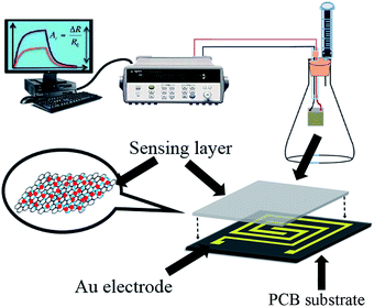
The surface morphologies of RGO and the SnO2–RGO hybrid composite were inspected by field emission scanning electron microscopy (FESEM, Hitachi S-4800). The microstructure for RGO and the SnO2–RGO film were characterized with an X-ray diffractometer (Rigaku D/Max 2500 PC, Japan) using Cu Kα (λ = 1.5418 Å) radiation with a 2θ scanning range of 20–50° at room temperature. The BET surface area and pore size of the SnO2–RGO composite were characterized by using a NOVA 1000e from Quantachrome Instruments, USA. The film thickness was measured by a surface profilometer (Tencor P10).A schematic illustration of the sensor structure and gas sensing experimental setup is demonstrated in Fig. 2. The acetone gas sensing experiment was performed at room temperature, and the response properties were measured using a data logger (Agilent 34970A). The gas sensing properties were investigated by exposing the gas sensors to various concentrations of the targeted acetone gas, and the desired gas concentration was obtained by injecting the required quantity of anhydrous liquid acetone into a sealed glass container using a syringe. The concentration of acetone gas in the chamber was calculated in ppm using the following equation:34,35
 | (1) |
The normalized response of the sensor was defined as S = (R0 − Rg)/R0 × 100%, where R0 and Rg were the sensor resistance in dry air and acetone gas, respectively. The time taken by a sensor to achieve 90% of the total resistance change is defined as the response or recovery time.
3. Results and discussion
3.1 SEM and XRD characterization
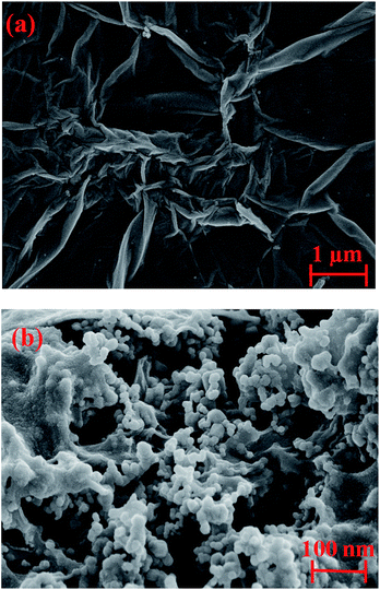
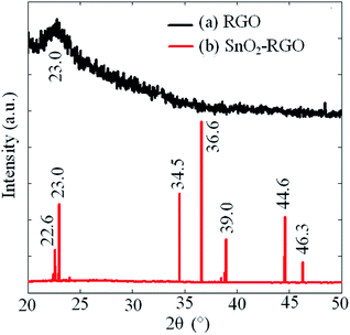
Fig. 3 shows the observed SEM images of RGO and the SnO2–RGO films. As shown in Fig. 3(a), it can be clearly seen that the RGO has wrinkles with overlap at the edges, and demonstrates randomly aggregated RGO sheets. The result in Fig. 3(b) indicates that SnO2 microspheres are attached on the surface of the RGO sheets, in which the presence of the SnO2 nanoparticles reveals that the hydrothermal treatment of RGO and SnCl4 solution is an effective method to synthesize the SnO2–RGO hybrid composite.Fig. 4 indicates the XRD spectrum for RGO and the SnO2–RGO film. The measured result in Fig. 4(a) shows an obvious peak at a 2θ angle of 23°, which is verified to be RGO by comparing with the standard card of RGO (PDF#74-2330 RIR 10.41). The interlayer distance of the RGO film is 3.86 Å (2θ = 23°), indicating the successful preparation of RGO through hydrothermal treatment. The broad diffraction peak of RGO indicates poor ordering of the sheets along the stacking direction, which implies that the sample was comprised mainly from single or only a few layers of RGO. Fig. 4(b) shows the XRD pattern of the SnO2–RGO hybrid composite, in which several of the strong diffraction peaks observed are attributed to the formation of SnO2 crystals (PDF#78-1063 RIR 5.29). It can also be observed that the peak related to RGO is overlapped with that of SnO2 at 2θ around 23°, due to the low amount of RGO sheets in the SnO2–RGO composite as well as the presence of the high intensity peak of SnO2.
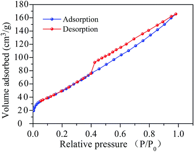
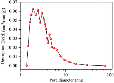
The film porous nanostructure of the SnO2–RGO composite was investigated by using Brunauer–Emmett–Teller (BET) measurements. The nitrogen adsorption–desorption isotherm curve is shown in Fig. 5. A distinct hysteresis loop can be seen at relative pressures of 0.4–1.0. This indicates the presence of a mesoporous structure and a relatively high surface area, in which a high specific surface area (SSA) of 153.4 m2 g−1 was determined.36 Apart from that, pore size distribution (PSD) analysis was achieved by employing the Barrett–Joyner–Halenda (BJH) method. As shown in Fig. 6, a primary pore diameter in the range of 2–5 nm is observed. A thickness profile measurement of the sensing film was performed using a profilometer (Tencor P10), and the film height of 984 ± 76 nm was measured. Taking advantage of the high specific surface area and small pore size, the SnO2–RGO composite possesses numerous adsorption sites to enhance the interactions between the acetone molecules and sensing materials.
3.2 Acetone-sensing properties
Fig. 7 shows the response curves of the SnO2–RGO and pure RGO film sensors measured under various acetone concentrations. The measurement was performed at room temperature with acetone gas exposure concentration ranging from 10 ppm to 2000 ppm, and the test was switched from low concentration to high concentration, and then conversely from high concentration to low concentration. Each exposure/recovery cycle was carried out for an exposure interval of 200 s followed by a recovery interval of 200 s in dry air. A clear increase in the sensor response is observed with the increasing gas concentration, and especially, the SnO2–RGO nanocomposite sensor exhibits a much higher response than that of the pure RGO film sensor.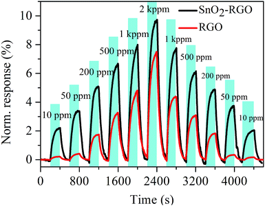 | ||
| Fig. 7 Response curves of the SnO2–RGO and pure RGO film sensors measured under various acetone gas concentrations. | ||
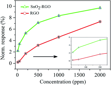
Fig. 8 plots the normalized response of the SnO2–RGO hybrid film sensor versus different concentrations of acetone gas, and also makes a comparison with that of the pure RGO film sensor. The response for the sensors exhibited an exponential increase with increasing acetone gas concentrations in a range of 10–2000 ppm, and the insert shows the response for the sensors exposed to gas concentrations lower than 200 ppm. The error bars represent standard deviation (SD) from the mean based on six sensors exposed to given concentrations of acetone gas. The SnO2–RGO film sensor exhibits an enhancement to acetone gas sensing properties, compared with the pure RGO film sensor.
Fig. 9 demonstrates the repeatability of the SnO2–RGO film sensor under three different concentrations of acetone gas at room temperature. The repeatability characteristic was recorded for five exposure/recovery cycles repeatedly for 10, 50 and 100 ppm, respectively. It was found that the SnO2–RGO film sensor exhibited a clear response–recovery behavior and stable repeatability for acetone gas sensing.
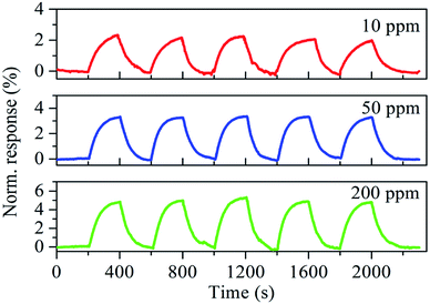
Fig. 10 shows the time-dependent response and recovery curves of the SnO2–RGO film sensor to acetone gas at different concentrations. Exposure of 300 s is performed to reach adsorption saturation, and 200 s is used for sensor recovery. The response and recovery times of around 107–146 s and 95–141 s, respectively, are observed for acetone gas sensing with concentrations ranging from 10 to 2000 ppm.
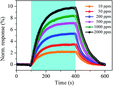 | ||
| Fig. 10 Typical response and recovery curves of the SnO2–RGO film sensor to acetone gas at different concentrations. | ||
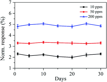
Fig. 11 shows the long-term stability of the SnO2–RGO film sensor exposed to the various concentrations of acetone gas. The measurements lasted for over 30 days and the responses were observed over different days. The three curves demonstrated the stability for the SnO2–RGO sensor exposed to 10, 50 and 200 ppm acetone gas, and there is no significant change among the measurements for at least 30 days. Table 1 presents the performance of the proposed acetone gas sensor working at room-temperature in comparison with previous reports.37–41 The response and measurement range for the prepared sensor are comparable to those of sensors made from metal oxides or polymers.
3.3 Acetone-sensing mechanism
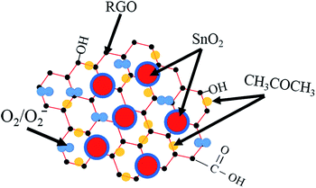
The high-performance of the above SnO2–RGO hybrid composite can be attributed to three factors. Firstly, the incorporation of SnO2 nanoparticles has a significant effect on preventing the aggregation of RGO sheets, leading to the formation of a 3D porous nanostructure with a much higher surface area and more active sites, such as vacancies, defects, oxygen functional groups as well as the sp2-bonded carbon, which greatly facilitates the adsorption and diffusion of acetone gas molecules.42,43 Secondly, the gas sensing performance of the SnO2–RGO nanostructures was attributed to the establishment of the heterojunction formed at the interface between n-type SnO2 nanoparticles and p-type RGO nanosheets. Once target gas molecules pass through the interface of these contacts, they lead to electronic sensitization by modulating depletion layers at the heterojunctions. The interaction between acetone gas molecules with the depletion layer can be depicted by the electron donation nature of the reducing gas, in which acetone gas acted as a donor of negative charge (reducing gas). The exposure of the film sensor to acetone gas leads to an enhancement of negative charge carriers to the n-type thin-film, and in turn results in a reduction in the overall electrical resistance of the sensor.44,45 Thirdly, surface oxygen species such as O2− are usually considered to be another possible sensing mechanism.46,47 Fig. 12 shows the adsorption illustration of acetone gas molecules adsorbed onto the sensing film. Chemisorbed oxygen molecules in the atmosphere are ionized to oxygen ions through the capture of free electrons from the surface of SnO2 nanoparticles (eqn (2) and (3)). Therefore, the sensor is in a high resistance state in atmospheric air as per the experimental observations. When the sensor is exposed to a reducing gas such as acetone gas, the gas molecules react with the oxygen ions on the surfaces of sensing film, as shown in eqn (4)–(6).48 Such reactions result in the retrieval of the trapped electrons back to the conduction band of the sensing film and lead to a decrease in resistance for the gas sensor.49| O2(gas) → O2(adsorbed) | (2) |
| O2(adsorbed) + e− → O2− | (3) |
| CH3COCH3 + O2− → CH3C+O + CH3O− + e− | (4) |
| CH3C+O →CH3+ + CO | (5) |
| CO + O2− → CO2 + e− | (6) |
The gas-sensing mechanism of RGO is generally ascribed to its p-type semiconducting behavior and is dominated by positive charge carriers (holes), whereas the adsorbed acetone gas on the sensing film surface serves as electron donors. The absorbed acetone gas molecules cause a change of hole concentration in RGO, resulting in the changes in the resistance of RGO. As demonstrated in Fig. 7 and 8, the gas response of the SnO2–RGO hybrid composite to variations of acetone gas was about 2-fold higher than that of the pure RGO film. This is mainly attributed to the high surface area, 3D porous nanostructure and special interactions between RGO sheets and SnO2 nanoparticles. K. K. Khun et al. have reported that SnO2 alone exhibited conductivity that was too low and did not display a detectable response to acetone vapor at room temperature,38 while our work suggests that the RGO doped SnO2 hybrid composite can be a potential pathway to achieve room temperature gas sensing with better sensing performance than their constituents alone. This work demonstrates that the as-prepared SnO2–RGO hybrid composite can be used for practical applications for monitoring acetone gas at room temperature.
4. Conclusions
In summary, we demonstrated a room-temperature acetone gas sensor with a SnO2–RGO hybrid composite as a sensing film, which was prepared by using a facile hydrothermal method. The surface morphology and microstructure for the film were characterized by scanning electron microscopy and X-ray diffraction, demonstrating good structures without irreversible restacking of sheets and agglomeration. The sensing properties of the SnO2–RGO hybrid film sensor were investigated by exposing it to acetone gas with a concentration range of 10 ppm to 2000 ppm at room temperature. It was found that the presented sensor exhibited not only excellent sensing behavior to acetone gas, but also a fast response–recovery time and good repeatability towards acetone detection, exhibiting the unique advantages of the SnO2–RGO hybrid composite as a building block for high-performance acetone gas sensors.Acknowledgements
This work was supported by the National Natural Science Foundation of China (Grant no. 51407200), the Science and Technology Development Plan Project of Shandong Province of China (Grant no. 2014GSF117035), the Promotive Research Foundation for the Excellent Middle-Aged and Youth Scientists of Shandong Province of China (Grant no. BS2012DX044), the Science and Technology Development Plan Project of Qingdao (Grant no. 13-1-4-179-jch), the Open Fund of National Engineering Laboratory for Ultra High Voltage Engineering Technology (Kunming, Guangzhou) (Grant no. NEL201518), and the Science and Technology Project of Huangdao Zone, Qingdao, China (Grant no. 2014-1-51).Notes and references
- I. Lee, S.-J. Choi, K.-M. Park, S. S. Lee, S. Choi, I.-D. Kim and C. O. Park, Sens. Actuators, B, 2014, 197, 300 CrossRef CAS PubMed
.
- L. Cheng, S. Y. Ma, X. B. Li, J. Luo, W. Q. Li, F. M. Li, Y. Z. Mao, T. T. Wang and Y. F. Li, Sens. Actuators, B, 2014, 200, 181 CrossRef CAS PubMed
.
- Q. Q. Jia, H. M. Ji, Y. Zhang, Y. Chen, X. H. Sun and Z. G. Jin, J. Hazard. Mater., 2014, 276, 262 CrossRef CAS PubMed
.
- T. Xiao, X.-Y. Wang, Z.-H. Zhao, L. Li, L. Zhang, H.-C. Yao, J.-S. Wang and Z.-J. Li, Sens. Actuators, B, 2014, 199, 210 CrossRef CAS PubMed
.
- Z. N. Wang, C. J. Wang and P. Lathan, IEEE Sens. J., 2014, 14, 1117 CrossRef
.
- J.-S. Do and S.-H. Wang, Sens. Actuators, B, 2013, 185, 39 CrossRef CAS PubMed
.
- T. I. Nasution, I. Nainggolan, S. D. Hutagalung, K. R. Ahmad and Z. A. Ahmad, Sens. Actuators, B, 2013, 177, 522 CrossRef CAS PubMed
.
- M. S. Khandekar, N. L. Tarwal, I. S. Mulla and S. S. Suryavanshi, Ceram. Int., 2014, 40, 447 CrossRef CAS PubMed
.
- W.-L. Jiao and L. Zhang, Trans. Nonferrous Met. Soc. China, 2012, 22, 1127 CrossRef CAS
.
- W. Q. Li, S. Y. Ma, J. Luo, Y. Z. Mao, L. Cheng, D. J. Gengzang, X. L. Xu and S. H. Yan, Mater. Lett., 2014, 132, 338 CrossRef CAS PubMed
.
- S. F. Bamsaoud, S. B. Rane, R. N. Karekar and R. C. Aiyer, Sens. Actuators, B, 2011, 153, 382 CrossRef CAS PubMed
.
- Y. D. Zhang, W. W. He, H. X. Zhao and P. J. Li, Vacuum, 2013, 95, 30 CrossRef CAS PubMed
.
- X. B. Li, S. Y. Ma, F. M. Li, Y. Chen, Q. Q. Zhang, X. H. Yang, C. Y. Wang and J. Zhu, Mater. Lett., 2013, 100, 119 CrossRef CAS PubMed
.
- X. H. Sun, H. M. Ji, X. L. Li, S. Cai and C. M. Zheng, Mater. Lett., 2014, 120, 287 CrossRef CAS PubMed
.
- M. Ding, D. C. Sorescu and A. Star, J. Am. Chem. Soc., 2013, 135, 9015 CrossRef CAS PubMed
.
- R. Rentenberger, A. Cayla, T. Villmow, D. Jehnichen, C. Campagne, M. Rochery, E. Devaux and P. Pötschke, Sens. Actuators, B, 2011, 160, 22 CrossRef CAS PubMed
.
- R. Ghasempour, A. I. Zad and M. R. H. Nezhad, Int. J. Nanomanuf., 2010, 5, 268 CAS
.
- A. K. Geim and K. S. Novoselov, Nat. Mater., 2007, 6, 183 CrossRef CAS PubMed
.
- X. S. Li, W. W. Cai, J. H. An, S. Y. Kim, J. H. Nah, D. X. Yang, R. Piner, A. Velamakanni, I. Jung, E. Tutuc, S. K. Banerjee, L. Colombo and R. S. Ruoff, Science, 2009, 324, 1312 CrossRef CAS PubMed
.
- M. D. Stoller, S. J. Park, Y. W. Zhu, J. H. An and R. S. Ruoff, Nano Lett., 2008, 8, 3498 CrossRef CAS PubMed
.
- S. J. Park and R. S. Ruoff, Nat. Nanotechnol., 2009, 4, 217 CrossRef CAS PubMed
.
- C. Lee, X. Wei, J. W. Kysar and J. Hone, Science, 2008, 321, 385 CrossRef CAS PubMed
.
- F. Schedin, A. K. Geim, S. V. Morozov, E. W. Hill, P. Blake, M. I. Katsnelson and K. S. Novoselov, Nat. Mater., 2007, 6, 652 CrossRef CAS PubMed
.
- G. H. Lu, L. E. Ocola and J. H. Chen, Nanotechnology, 2009, 20, 445502 CrossRef PubMed
.
- R. Pearce, T. Iakimov, M. Andersson, L. Hultman, A. L. Spetz and R. Yakimova, Sens. Actuators, B, 2011, 155, 451 CrossRef CAS PubMed
.
- M. G. Chung, D. H. Kim, H. M. Lee, T. Kim, H. H. Choi, D. K. Seo, J.-B. Yoo, S.-H. Hong, T. J. Kang and Y. H. Kim, Sens. Actuators, B, 2012, 166–167, 172 CrossRef CAS PubMed
.
- H. J. Yoon, D. H. Jun, J. H. Yang, Z. X. Zhou, S. S. Yang and M. M. C. Cheng, Sens. Actuators, B, 2011, 157, 310 CrossRef CAS PubMed
.
- A. Ghosh, D. J. Late, L. S. Panchakarla, A. Govindaraj and C. N. R. Rao, J. Exp. Nanosci., 2009, 4, 313 CrossRef CAS
.
- Q. W. Huang, D. W. Zeng, S. Q. Tian and C. S. Xie, Mater. Lett., 2012, 83, 76 CrossRef CAS PubMed
.
- F. Liu, X. F. Chu, Y. P. Dong, W. B. Zhang, W. Q. Sun and L. M. Shen, Sens. Actuators, B, 2013, 188, 469 CrossRef CAS PubMed
.
- S.-J. Choi, F. Fuchs, R. Demadrille, B. Grévin, B.-H. Jang, S.-J. Lee, J.-H. Lee, H. L. Tuller and I.-D. Kim, ACS Appl. Mater. Interfaces, 2014, 6, 9061 CAS
.
- H. J. Song, L. C. Zhang, C. L. He, Y. Qu, Y. F. Tian and Y. Lv, J. Mater. Chem., 2011, 21, 5972 RSC
.
- S. S. Mali, P. S. Shinde, C. A. Betty, P. N. Bhosale, W. J. Lee and P. S. Patil, Appl. Surf. Sci., 2011, 257, 9737 CrossRef CAS PubMed
.
- X. Wang, F. Cui, J. Lin, B. Ding, J. Yu and S. S. Al-Deyab, Sens. Actuators, B, 2012, 171–172, 658 CrossRef CAS PubMed
.
- X. D. Li, Y. Q. Chang and Y. Long, Mater. Sci. Eng., C, 2012, 32, 817 CrossRef CAS PubMed
.
- M. Liu, L. Gan, W. Xiong, Z. Xu, D. Zhu and L. Chen, J. Mater. Chem. A, 2014, 2, 2555 CAS
.
- J. S. Do and S. H. Wang, Sens. Actuators, B, 2013, 185, 39 CrossRef CAS PubMed
.
- K. K. Khun, A. Mahajan and R. K. Bedi, J. Appl. Phys., 2009, 106, 124509 CrossRef PubMed
.
- C. J. Shao, Y. Chang and Y. Long, Sens. Actuators, B, 2014, 204, 666 CrossRef CAS PubMed
.
- R. A. Guirado-Lopez, M. Sanchez and M. E. Rincon, J. Phys. Chem. C, 2007, 111, 57 CAS
.
- L. Mazeina, V. M. Bermudez, F. K. Perkins, S. P. Arnold and S. M. Prokes, Sens. Actuators, B, 2010, 151, 114 CrossRef CAS PubMed
.
- P. A. Russo, N. Donato, S. G. Leonardi, S. Baek, D. E. Conte, G. Neri and N. Pinna, Angew. Chem., Int. Ed., 2012, 51, 11053 CrossRef CAS PubMed
.
- Q. Q. Lin, Y. Li and M. J. Yang, Sens. Actuators, B, 2012, 173, 139 CrossRef CAS PubMed
.
- B. D. Guo, Q. Liu, E. D. Chen, H. W. Zhu, L. Fang and J. R. Gong, Nano Lett., 2010, 10, 4975 CrossRef CAS PubMed
.
- Q. T. Tran, H. T. My-Hoa, D. H. Yoo, T. V. Cuong, S. H. Hur, J. S. Chung, E. J. Kim and P. A. Kohl, Sens. Actuators, B, 2014, 194, 45 CrossRef CAS PubMed
.
- C. Hsu, K. Chen, T. Tsai and T. Hsueh, Sens. Actuators, B, 2013, 182, 190 CrossRef CAS PubMed
.
- H.-J. Kim and J.-H. Lee, Sens. Actuators, B, 2014, 192, 607 CrossRef CAS PubMed
.
- S.-J. Chang, T.-J. Hsueh, I.-C. Chen, S.-F. Hsieh, S.-P. Chang, C.-L. Hsu, Y.-R. Lin and B.-R. Huang, IEEE Trans. Nanotechnol., 2008, 7, 754 CrossRef
.
- X. J. Luo, Z. Lou, L. L. Wang, X. J. Zheng and T. Zhang, New J. Chem., 2014, 38, 84 RSC
.
| This journal is © The Royal Society of Chemistry 2015 |

![[thin space (1/6-em)]](https://www.rsc.org/images/entities/char_2009.gif) 000 ppm
000 ppm