Microfluidic fabrication of chitosan microfibers with controllable internals from tubular to peapod-like structures†
Xiao-Heng Hea,
Wei Wang*a,
Ke Denga,
Rui Xiea,
Xiao-Jie Jua,
Zhuang Liua and
Liang-Yin Chu*ab
aSchool of Chemical Engineering, Sichuan University, Chengdu, Sichuan 610065, China. E-mail: wangwei512@scu.edu.cn; chuly@scu.edu.cn; Fax: +86-28-8546-0682; Tel: +86-28-8546-0682
bState Key Laboratory of Polymer Materials Engineering, and Collaborative Innovation Center for Biomaterials Science and Technology, Sichuan University, Chengdu, Sichuan 610065, China
First published on 19th November 2014
Abstract
Here we report on a simple and flexible approach for continuous in situ fabrication of chitosan microfibers with controllable internals from tubular to peapod-like structures in microfluidics. Tubular and peapod-like jet templates can be generated at stable operation regions for template synthesis of chitosan microfibers with controllable tubular and peapod-like internals. The structure of each jet template can be precisely adjusted by simply changing the flow rates to tailor the structures of the resultant tubular and peapod-like chitosan microfibers. Both the tubular and peapod-like microfibers possess sufficient mechanical properties for further handling for biomedical applications. The tubular microfibers are used as biocompatible artificial vessels for transporting fluid, which is promising for delivering nutrition and blood for tissue engineering and cell culture. The peapod-like microfibers with controllable and separate oil cores can serve as multi-compartment systems for synergistic encapsulation of multiple drugs, showing great potential for developing drug-loaded medical patches for wound healing. The approach proposed in this study provides a facile and efficient strategy for controllable fabrication of microfibers with complex and well-tailored internals for biomedical applications.
Introduction
Microfibers from natural biopolymers show great potential in the fabrication of 3D matrices as tissue engineering scaffolds,1–4 implantable therapeutic systems5 and medical patches for biomedical applications.6–8 In particular, controllable creation of micro-sized compartmental internals within microfibers are crucial for enhancing their functions in biomedical fields. For example, microfibers with tubular microchannels can serve as artificial microvessels for transporting fluids and culturing vascular cells,9–12 and as bio-microreactors for enzyme-immobilized biocatalysis.13 Microfibers with well-tailored multicompartments can be used to controllably encapsulate actives that benefit cell growth or wound healing for developing advanced scaffolds for tissue engineering, or for fabricating drug-loaded medical patches for wound healing. Among the natural biopolymers, chitosan is widely used for cell culture14–16 and wound healing,17–19 due to its excellent biocompatibility, biodegradability, bioadhesive activity, and wound healing activity. Therefore, development of microfibers with well-controlled micro-sized compartmental internals from chitosan exhibits significant importance for biomedical applications.Typically, microfibers from natural biopolymers, such as chitosan, alginate, and collagen, can be generated by electrospinning,7,20–22 wet spinning,23–26 and microfluidic approaches.1,2,15,16,27,28 Electrospinning and wet spinning are well-established techniques that can produce natural biopolymer fibers with submicrometer and micrometer diameters.29 However, it is difficult for these techniques to individually and precisely create controllable complex internals within the fibers. Recently developed microfluidic techniques, with excellent manipulation on microflows,30–34 show great potential for manufacturing microfibers with controllable structures.1,12,35,36 Typically, solid microfibers can be produced by using templates of core flows that are hydrodynamically shaped by continuous phase.12,14,15,27,37 Creation of tubular microchannel compartment in microfibers can be achieved by using tubular flows with cylinder-in-cylinder structures.10,13,16 The change in flow rates offers a simple and efficient approach to control the microfiber structures. By using droplet-containing continuous flow in microfluidic channels as templates, more complex Ca–alginate microfibers with separate compartments containing oil and particles are developed for multi-encapsulation.35 However, the requirement for devices with outlets of different dimensions to control the microfiber diameter is usually troublesome. Simpler flow-rate control over the diameter of such compartmental microfibers can be achieved by hydrodynamic shaping of the droplet-contained flow templates with additional continuous phase, from which Ca–alginate coding microfibers are generated with gas compartments.1 However, better control of the internal structures, such as the compartment size and the distance between compartments, is still desired. Moreover, further development of microfibers with multiple compartments from chitosan via microfluidics is still in demand. The mild flow conditions and highly-efficient encapsulation of microfluidic techniques allow the efficient loading of microfibers with sensitive substances such as cells and proteins for biomedical applications.29 Therefore, fabrication of chitosan microfibers with controllable structures, especially with controllable compartmental internals from microfluidics, is highly desired.
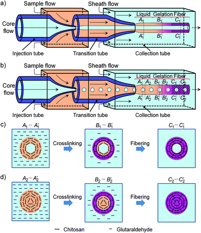
Here we report on a simple and flexible microfluidic strategy for controllable fabrication of chitosan microfibers with controllable internals from tubular to peapod-like structures. First, aqueous tubular jets with cylinder-in-cylinder flow structures are generated from microfluidics as templates for continuous fabrication of chitosan microfibers with controllable tubular internals (Fig. 1a). Then, peapod-like jets are generated by converting the continuous inner cylinder flow of tubular jets into discrete droplets for fabricating chitosan microfibers with controllable peapod-like internals (Fig. 1b). An oil phase is used to produce the discrete droplets for encapsulating oil-soluble substances. The structure of each jet template can be precisely manipulated by simply changing the flow rates, which allows accurate engineering of the structures of the resultant tubular and peapod-like chitosan microfibers. Both the tubular and peapod-like microfibers show sufficient mechanical properties for further handling for biomedical applications. The tubular microfibers exhibit excellent performance as biocompatible artificial vessels for microfluid transport, and we demonstrate this by using aqueous solution of methylene blue trihydrate and fresh rabbit blood plasma as model fluids. Meanwhile, the peapod-like microfibers, with separate oil “peas” as compartments, allow controllable synergistic encapsulation of both water-soluble and oil-soluble drugs. These chitosan microfibers with controllable internals are promising for developing artificial microvessels for transporting blood and nutrition for tissue engineering and cell culture, or for developing drug-loaded medical patches for wound treatment. Moreover, our approach provides a facile strategy for fabrication of microfibers with complex and well-controlled compartmental internals for biomedical applications.
Experimental
Materials
Water-soluble chitosan (Mw = 300![[thin space (1/6-em)]](https://www.rsc.org/images/entities/char_2009.gif) 000, degree of deacetylation = 90%) was provided by Ji'nan Haidebei Marine Bioengineering. Glutaraldehyde (GA) (50%), acetic acid, polyethylene glycol (PEG) (Mw = 20
000, degree of deacetylation = 90%) was provided by Ji'nan Haidebei Marine Bioengineering. Glutaraldehyde (GA) (50%), acetic acid, polyethylene glycol (PEG) (Mw = 20![[thin space (1/6-em)]](https://www.rsc.org/images/entities/char_2009.gif) 000), bromoeosin and agar (Mw = 3000–9000) were purchased from Chengdu Kelong Chemical Reagents. Benzyl benzoate (BB) was obtained from Sinopharm Chemical Reagents. Lumogen®F Red 300 (LR300) was obtained from BASF. Sudan Black was purchased from China National Pharmaceutical Group Corporation. Methylene blue trihydrate was obtained from Tianjin Bodi Chemical Reagents.
000), bromoeosin and agar (Mw = 3000–9000) were purchased from Chengdu Kelong Chemical Reagents. Benzyl benzoate (BB) was obtained from Sinopharm Chemical Reagents. Lumogen®F Red 300 (LR300) was obtained from BASF. Sudan Black was purchased from China National Pharmaceutical Group Corporation. Methylene blue trihydrate was obtained from Tianjin Bodi Chemical Reagents.
The fresh plasma was obtained from a female New Zealand rabbit (adult, 2 kg). All the animal experiments were performed under a strict protocol approved by the Institute Guidelines on Animal Experimentation of Sichuan University in China. First, the rabbit fresh blood was collected using vacuum tubes containing sodium citrate as the anticoagulant (the volume ratio of anticoagulant to blood was 1![[thin space (1/6-em)]](https://www.rsc.org/images/entities/char_2009.gif) :
:![[thin space (1/6-em)]](https://www.rsc.org/images/entities/char_2009.gif) 9). Next, after centrifugation of the blood sample at 3000 rpm for 10 min, the supernatant liquid (fresh rabbit plasma) was collected for further use.
9). Next, after centrifugation of the blood sample at 3000 rpm for 10 min, the supernatant liquid (fresh rabbit plasma) was collected for further use.
Fabrication of glass-capillary microfluidic device
A capillary microfluidic device that was used for microfiber fabrication was fabricated by assembling glass capillary tubes on glass slides, similar to our previous work (Fig. 1a and b).38 Briefly, two cylinder capillaries with an outer diameter of 1 mm and an inner diameter of 550 μm were used as the injection tube and the transition tube. The front-ends of the injection tube and the transition tube were tailored into tapered orifices by micropuller (Narishige) and microforge (Narishige) to make the inner diameters of the tapered orifices 100 and 300 μm, respectively. The injection tube and the transition tube were inserted into a square capillary with inner square dimension of 1 mm. Then, another square capillary that was used as the collection tube was connected with the tapered orifice of the transition tube. These assembled capillaries were fixed on a glass plate, and connected with plastic tubes for injecting fluids by transparent epoxy resin. The microfluidic device was finally obtained after sealing of the remaining flow channels to prevent leaking.Microfluidic fabrication of tubular and peapod-like chitosan microfibers
For the fabrication of chitosan microfibers with tubular and peapod-like internals, an aqueous solution containing 4.0 wt% water-soluble chitosan and 2.0 wt% acetic acid was used as the sample flow, and an aqueous solution containing 50.0 wt% GA was used as the sheath flow (Fig. 1a and b) (to optimize the fabrication conditions for preparing the tubular and peapod-like chitosan microfibers, solid chitosan microfibers were first prepared. Please see Fig. S1–S3 in the ESI† for details). Different solutions were used as the core flow depending on the internal structure of the microfiber. These three flows were injected using syringe pumps (LSP01-1A, Baoding Longer Precision Pumps) at appropriate flow rates to generate stable and controllable jets as templates for microfiber fabrication (Fig. 1).For fabrication of chitosan microfibers with tubular internals, an aqueous solution containing 20.0 wt% PEG was used as the core flow (Fig. 1a). First, the core flow was hydrodynamically shaped by the aqueous sample flow to form a stable jet in the transition tube. The interface of the jet can be stable due to the low interfacial tension between the two aqueous flows. Such a tubular jet was then shaped and surrounded by the sheath flow in the collection tube, forming a stable coaxial three-phase flow (Fig. 1a). Upon contacting, GA in the sheath flow diffused into the sample flow, resulting in the crosslinking of chitosan in the sample flow and the production of chitosan microfibers with tubular internals (Fig. 1c).
For fabrication of chitosan microfibers with peapod-like internals, organic solvent BB was used as the core flow (Fig. 1b). First, the core flow was emulsified into monodispersed droplets by the sample flow in the transition tube. Then, the sample flow that carried the BB droplets was hydrodynamically shaped by the sheath flow, generating a peapod-like jet with cylinder sample flow containing discrete droplets of core flow (Fig. 1b). Similarly, upon contacting, GA diffused from the sheath flow into the sample flow, and crosslinked the chitosan to form a chitosan shell encapsulated with uncrosslinked droplets, resulting in microfibers with peapod-like internals (Fig. 1c and d). The crosslinking process of the droplet-containing space (cross-section A1–A1′, B1–B1′and C1–C1′ in Fig. 1b) and the tight space (cross-section A2–A2′, B2–B2′ and C2–C2′ in Fig. 1b) of the peapod-like microfibers are illustrated in Fig. 1c and d, respectively.
The obtained microfibers with tubular and peapod-like internals were collected in an aqueous solution of 50.0 wt% GA overnight to completely crosslink the chitosan. The fabrication process should be operated in a fume hood for eye and skin protection due to the harmful effects of GA. To fully remove unreacted components such as GA, the resultant microfibers were sufficiently washed and then stored in pure water for further use. The droplets in the peapod-like chitosan microfibers remained as compartments for further drug loading.
Investigation of the morphology of jet templates and chitosan microfibers
The formation process of jet templates was monitored by inverted optical microscope (IX71, Olympus) equipped with a high-speed digital camera (Miro3, Phantom, Vision Research). The effect of flow rates on the morphology of the tubular and peapod-like jet templates was quantitatively studied by inverted optical microscope. For the tubular microfibers, 0.5 wt% methylene blue trihydrate and bromoeosin were added to the core flow and the sample flow, respectively, to visualize the formation process. For the peapod-like microfibers, 0.5 wt% Sudan Black was added to the core flow instead of methylene blue trihydrate.The structures of the tubular and peapod-like microfibers were observed by optical microscope (DM4000B-M, Leica) and scanning electron microscope (SEM, G2 Pro, Phenom). The diameters of the jet templates, and the droplet diameters and the droplet distance of the peapod-like microfibers were measured from the high-speed snapshots. The droplet diameter of the peapod-like microfibers was defined as the average of the vertical diameter and the horizontal diameter of the droplet. The droplet distance was defined as the distance between the centers of two neighbouring droplets. The shell thickness was defined as half of the difference between the outer diameter of the most convex interfaces of the peapod-like jet and the vertical diameter of the droplet.
Mechanical properties of chitosan microfibers
The mechanical properties of dehydrated chitosan microfibers were investigated by electronic universal testing machine (EZ-LX1kN, Shimadzu) with a 10 N sensor. Three types of microfibers, each with outer diameter of 150 μm, including tubular microfibers with wall thickness of 50 μm and two types of peapod-like microfibers with shell thickness of 10 μm and 20 μm, were used as samples. For measurement of the mechanical properties, the sample gauge length between two clamps was 20 mm and the strain rate was 10 mm min−1.Chitosan microfibers with tubular internals for microfluid transport
For microfluid transport, the tubular chitosan microfibers with inner diameter of 200 μm were fixed into agar gel matrix. An aqueous solution of 0.5 wt% methylene blue trihydrate and fresh rabbit blood plasma were respectively used as the model fluids. The height of the liquid (h) in the tubular channel of the microfiber was measured to estimate the microfluidic transport capability. The contact angle θ between the model liquid and the microfiber wall was determined by using an optical tensiometer (DSA25, Krüss GmbH) at 25 °C in air to evaluate the wettability of the model liquid. A flat chitosan film with the same crosslinked matrix as that of the chitosan microfiber wall was prepared for the contact angle measurement.Chitosan microfibers with peapod-like internals for synergistic encapsulation
Encapsulation of hydrophobic drugs in the peapod-like chitosan microfibers was demonstrated by using oil-soluble fluorescent LR300 as the model drug. 0.5 wt% LR300 was added into the core flow to prepare LR300-loaded microfibers. Since the crosslinked chitosan matrix can also show green fluorescence,39,40 the microfiber morphology was studied by confocal laser scanning microscope (CLSM, SP5-II, Leica), with excitation at ∼488 nm and ∼543 nm for observing the chitosan matrix and LR300, respectively.Synergistic encapsulation of both hydrophobic and hydrophilic drugs in the peapod-like chitosan microfiber was demonstrated by using oil-soluble Sudan Black and water-soluble Eosin Y as the model drugs. 0.5 wt% Sudan Black and 0.05 wt% Eosin Y were added into the core flow and sample flow respectively to obtain microfibers for such a synergistic encapsulation. The microfiber morphology was observed using a digital microscope (GE-5, Aigo).
Results and discussion
Effects of flow rates on the morphology of tubular jet templates
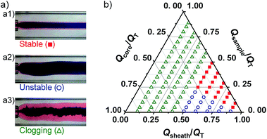
To generate jet templates with stable tubular morphology for fabricating tubular chitosan microfibers, the effects of flow rates on the jet morphologies were systematically investigated (Fig. 2). Typically, under different flow rate conditions, three representative morphologies, including stable (Fig. 2a1), unstable (Fig. 2a2) and clogging (Fig. 2a3) morphologies, can be observed for the jet templates that formed in the microfluidic device. The unstable and clogging morphologies respectively represent a fluctuant tubular jet and a chaotic jet that wets the microchannel wall. As shown in the ternary phase-like diagram of Fig. 2b, a change in the flow rates of the core flow (Qcore), sample flow (Qsample) and sheath flow (Qsheath) results in jet morphologies shifting between the three typical morphologies. When changing each of the three flow rates, the total flow rate, which is the sum of Qcore, Qsample and Qsheath, is kept constant. The ternary phase-like diagram shows that stable tubular jet templates can be generated at flow rate conditions located in the red square region between the Qsheath/QT and Qsample/QT axes (Fig. 2b). With relatively high Qsheath and Qsample, and a low Qcore, the core flow and sample flow can be completely surrounded by the sample flow and the sheath flow, respectively. At flow rate conditions located in the blue circle region of the diagram, the relatively low Qsample leads to unstable jets with fluctuant morphologies. When the flow rates are set in the green triangle region, the sheath flow cannot completely envelop the core flow and the sample flow due to the relatively low Qsheath, thus leading to sticking of the sample flow onto the microchannel wall. Therefore, the ternary phase-like diagram provides an operation guide for setting flow rates for generating stable tubular jet templates.Fabrication of chitosan microfibers with controllable tubular internals
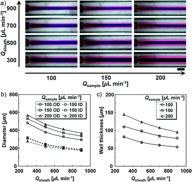
Aqueous tubular jets are generated as templates for preparing chitosan microfibers with controllable tubular internals. The core flow of the jet template becomes the tubular internal and the sample flow becomes the microfiber wall.Since the microfiber structure largely depends on the structure of the jet template, fine adjustment of the jet structure creates fantastic opportunities for precise manipulation of the microfiber structure. With microfluidics, such an accurate control can be achieved by simply changing flow rates (Fig. 3a–c). When Qcore is kept constant (50 μL min−1), adjustment of Qsample and Qsheath allows precise and individual control of the jet structure. As shown in Fig. 3a, at fixed Qsample, the increase of Qsheath results in jet templates with smaller inner diameter (ID) and outer diameter (OD). For example, at Qsample = 200 μL min−1, the ID and OD of the jet show a 35.0% and 37.0% decrease, respectively, when Qsheath varies from 300 to 900 μL min−1. At fixed Qsheath, increase of Qsample leads to an increase of the OD of the jet templates; however, only a slight decrease in their inner diameter is observed (Fig. 3a and b). At Qsheath = 900 μL min−1, when Qsample increases from 100 to 200 μL min−1, a 24.0% increase is observed for the OD of jet, but only a 6.0% decrease for the ID. Moreover, the effect of Qsheath and Qsample on the wall thickness of the jet templates is also investigated. As shown in Fig. 3c, at fixed Qcore and Qsample, the wall thickness decreases with increasing Qsheath, while at fixed Qcore and Qsheath, the wall thickness increases with increasing Qsample. These results show the excellent control of our microfluidic strategy for adjusting the inner and outer diameter, and the wall thickness of the jet templates for microfiber structure control.
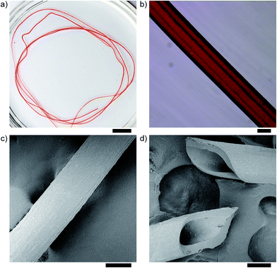
With such highly controllable jet templates, chitosan microfibers with tubular internals can be fabricated by crosslinking the chitosan in the jet, and collected by spinning procedure (Fig. 4a). As shown in Fig. 4b, the chitosan microfiber exhibits uniform outer diameter and well-defined inner tubular microchannels. Such a tubular structure with a uniform wall thickness can be further seen in the SEM images of the microfiber and its cross-section (Fig. 4c and d). It is noted that the decrease in microfiber size in Fig. 4c and d as compared to that in Fig. 4b is due to the shrinkage of the chitosan matrix during the drying process for preparing the SEM sample.
Effects of flow rates on the morphology of peapod-like jet templates
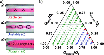
To generate jet templates with stable peapod-like morphology for fabricating peapod-like chitosan microfibers, effects of flow rates on the jet morphologies were also systematically studied (Fig. 5). Similarly, three representative morphologies, including stable (Fig. 5a1), unstable (Fig. 5a2) and clogging (Fig. 5a3) morphologies, can be observed for the jet templates when changing flow rates. As shown in Fig. 5b, the ternary phase-like diagram of the peapod-like jets exhibits a relatively narrow operation region (red square) for obtaining stable morphologies, as compared to that of the tubular jets. In this red square region, the core flow can be broken into monodispersed droplets by the sample flow with relatively high Qsample, resulting in stable sample flow carrying well-dispersed droplets of the core flow. The droplet-containing sample flow can then be shaped into a stable jet by the sheath flow with relatively high Qsheath, thus producing a stable peapod-like jet template. When Qcore increases and Qsample decreases (blue circle region), the core flow leads to fluctuations in the sample flow. Although oil droplets of the core flow can also be generated, it is difficult to manipulate the morphology of the unstable waving jet by simply changing the flow rates. Similarly, with flow rates set at the green triangle region, where the Qsheath/QT is less than 0.6, wetting of sample flow onto the microchannel wall is observed. This ternary phase-like diagram provides a valuable guideline for generating stable peapod-like jet templates.Fabrication of chitosan microfibers with controllable peapod-like internals
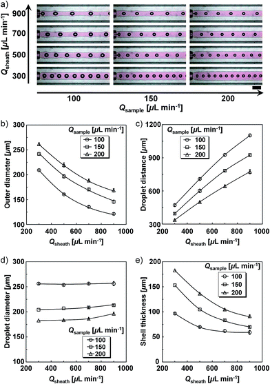
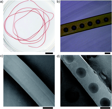
Chitosan microfibers with controllable peapod-like structures are fabricated by using a cylinder jet containing discrete oil droplets as templates. Crosslinking of the chitosan in the cylinder jet can create peapod-like microfibers with separate oil droplets serving as the individual “pea” compartments for controllable encapsulation. Similarly, the excellent manipulation of microfluidics on droplets and flows enables precise control of the jet structure as well as the resultant microfiber structure. As shown in Fig. 6, at a fixed Qcore (20 μL min−1), changes of Qsample and Qsheath enable fine adjustment of the OD of the jet, the droplet size, the shell thickness, and the distance between every two droplets, providing controllable templates for microfiber fabrication. The OD of the jet decreases with increasing Qsheath and increases with increasing Qsample when the other two flow rates are kept constant (Fig. 6a and b). For example, at Qsample = 200 μL min−1, the OD of the jet decreases by 36.0% when Qsheath increases from 300 to 900 μL min−1. At fixed Qsheath = 900 μL min−1, the OD of the jet increases 39.0% when Qsample increases from 100 to 200 μL min−1. The effects of Qsample and Qsheath on the droplet distance within the microfiber are shown in Fig. 6c. The distance between the droplets increases with decreasing Qsample and increasing Qsheath. Such distance control defines the number of droplets per unit length of microfiber. As compared to Qsheath, Qsample shows more obvious influence on the droplet size, where the droplet diameter decreases with increasing Qsample when the other two flow rates are kept constant (Fig. 6d). Meanwhile, the shell thickness of the jet templates can also be tuned by changing the Qsheath and Qsample. As shown in Fig. 6e, at fixed Qcore and Qsample, the shell thickness decreases with increasing Qsheath, while at fixed Qcore and Qsheath, the shell thickness increases with increasing Qsample. All the results demonstrate the precise and flexible controllability of the jet structure for fabricating microfibers with peapod-like internals.Crosslinking of the controllable jet templates produces peapod-like chitosan microfibers, which can be continuously collected by a spinning procedure (Fig. 7a). The chitosan microfiber exhibits a uniform peapod-like structure similar to the jet template, with monodispersed droplets uniformly distributed in the microfiber as separate “pea” compartments (Fig. 7b). The SEM images of the microfiber and its cross-section further confirm such peapod-like structure with uniformly aligned compartments (Fig. 7c and d). All the results show the great power of our strategy for preparing chitosan microfibers with controllable compartmental internals.
Mechanical properties of tubular and peapod-like chitosan microfibers
The mechanical properties of dehydrated chitosan microfibers were investigated by using tubular microfibers and two types of peapod-like microfibers with different shell thickness as samples (see Fig. S4 and Table S1 in the ESI† for details). The stress–strain curves show that, under the same test conditions, all three types of microfibers show almost linear elastic behaviours until the microfibers are broken. All the dehydrated microfibers exhibit fracture strains of about 2.5%, indicating that they are hard to strain. Moreover, the tensile strength of the microfibers increases with increasing shell thickness. The tensile strength of the tubular microfibers with wall thickness of 50 μm is 56.7 ± 4.3 MPa, while those of the peapod-like microfibers with shell thickness of 20 μm and 10 μm are 29.3 ± 4.0 MPa and 19.7 ± 2.4 MPa, respectively. The Young's modulus of the tubular microfibers and the peapod-like microfibers with shell thickness of 20 μm and 10 μm are 2185.4 ± 295.7 MPa, 1362.8 ± 243.1 MPa and 875.7 ± 127.0 MPa, respectively. The results indicate the produced chitosan microfibers have good mechanical properties for further handling for biomedical applications, and the mechanical properties can be adjusted by tuning their structures.Chitosan microfibers with controllable tubular internals for microfluid transport
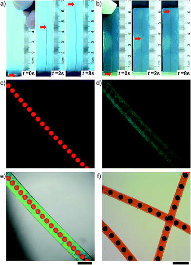
Microfibers with tubular inner channels, such as blood vessels, are important in living organisms due to their function for delivering liquid and nutrition.10 The tubular microfibers with biocompatible chitosan matrix have good potential as artificial microvessels for such transportation. We demonstrate the microfluid transport of our tubular chitosan microfibers by using an aqueous solution of methylene blue trihydrate (blue color) (Fig. 8a) and fresh rabbit blood plasma (light yellow color) (Fig. 8b) as the model fluids. The tubular chitosan microfiber is embedded in an agar gel to mimic the microvessel embedded in tissue. The end of the tubular microfiber is immersed in the model liquids for microfluid transport. As shown in Fig. 8a and b, both liquids move smoothly and reach their max height (hmax) within ∼8 s in the embedded tubular microfibers, exhibiting excellent fluid transportation. The blue-dyed liquid moves faster than the rabbit blood plasma, and reaches a higher hmax (6.6 cm) than that of the rabbit blood plasma (6.0 cm). This is mainly due to the smaller contact angle of the blue-dye solution (θdye = 36°) than that of the rabbit blood plasma (θplasma = 45°), indicating better wettability between the blue-dye solution and the microfiber wall. The results show the potential of such tubular chitosan microfibers as microvessels for transporting blood in artificial tissues and delivering nutrition solution in cell-culture systems.Chitosan microfibers with controllable peapod-like internals for synergistic encapsulation
The peapod-like microfibers with hydrophilic chitosan matrix and hydrophobic oil droplets can serve as multicompartmental micro-carriers for both water-soluble and oil-soluble molecules. We first demonstrate the ability of the peapod-like chitosan microfibers to encapsulate oil-soluble drugs by using LR300 as the model molecules. The oil peas that are uniformly distributed within the chitosan microfibers can serve as separate hydrophobic micro-compartments for loading LR300. The oil peas with red fluorescent dye confirm the successful incorporation of LR300 in the crosslinked chitosan microfiber (green color) (Fig. 8c–e). The oil-soluble drugs are usually loaded in the oil peas of the microfibers during their fabrication. Thus, the use of GA for crosslinking may limit the choice of encapsulating materials. For example, when encapsulating bioactive molecules, oils that show poor solubility for GA should be employed as the peas to protect the contents. Compared with single drug encapsulation, co-delivery of multiple drugs usually enables synergistic efficacy for more efficient treatment of diseases such as cancer.41,42 Such a synergistic encapsulation for both oil-soluble and water-soluble drugs can also be realized by further employing the hydrophilic chitosan matrix for encapsulation. To demonstrate the synergistic encapsulation, oil-soluble Sudan Black (black color) and water-soluble bromoeosin (red color) that are used as model drugs are respectively encapsulated in the inner oil droplets and chitosan matrix (Fig. 8f). The excellent control of the microfiber diameter, the droplet size and the droplet distance enables individual and accurate optimization of the encapsulation of each drug in the microfiber to ensure optimized efficacy. Since fabrics can be woven from the chitosan microfibers (Fig. S3a†), these peapod-like microfibers could be potentially used for fabricating drug-loaded medical patches for healing wounds. Furthermore, because droplets of different compositions can also be introduced with advanced microfluidic devices,43 more versatile drugs, even incompatible ones, can be loaded in a single microfiber for more diverse synergistic encapsulation.Conclusions
In summary, a simple and flexible strategy based on microfluidics has been developed for continuous fabrication of chitosan microfibers with controllable internals from tubular to peapod-like structures. Tubular and peapod-like jets are generated as templates for in situ fabricating chitosan microfibers with controllable tubular and peapod-like internals, respectively, in microfluidic devices. The excellent flow-rate-dependent manipulation of the structure of the jet templates, together with the in situ synthesis process, enables facile and flexible adjustment of the resultant microfiber structures. Both the tubular and peapod-like microfibers exhibit good mechanical properties for further handling for biomedical applications. The tubular microfibers can work as biocompatible artificial vessels for transporting fluids such as water and blood, showing great potential in bio-applications such as tissue engineering and cell culture. The peapod-like microfibers with separate oil cores can serve as multi-compartment systems for synergistic encapsulation of multiple drugs; thus they are highly promising for developing drug-loaded medical patches for wound healing. Moreover, these oil cores can also be removed by washing with ethanol to create hollow compartments for loading water-soluble components. This study provides a facile and efficient strategy for controllable fabrication of microfibers with complex and well-tailored internals for biomedical applications.Acknowledgements
The authors gratefully thank the support from the National Natural Science Foundation of China (21136006, 21306117), Program for Changjiang Scholars and Innovative Research Team in University (IRT1163), and the Specialized Research Fund for the Doctoral Program of Higher Education by the Ministry of Education of China (20130181120063).References
- E. Kang, G. S. Jeong, Y. Y. Choi, K. H. Lee, A. Khademhosseini and S. H. Lee, Nat. Mater., 2011, 10, 877–883 CrossRef CAS PubMed.
- H. Onoe, T. Okitsu, A. Itou, M. Kato-Negishi, R. Gojo, D. Kiriya, K. Sato, S. Miura, S. Iwanaga, K. Kuribayashi-Shigetomi, Y. T. Matsunaga, Y. Shimoyama and S. Takeuchi, Nat. Mater., 2013, 12, 584–590 CrossRef CAS PubMed.
- E. Kang, Y. Y. Choi, S. K. Chae, J. H. Moon, J. Y. Chang and S. H. Lee, Adv. Mater., 2012, 24, 4271–4277 CrossRef CAS PubMed.
- M. A. Daniele, A. A. Adams, J. Naciri, S. H. North and F. S. Ligler, Biomaterials, 2014, 35, 1845–1856 CrossRef CAS PubMed.
- Y. Jun, M. J. Kim, Y. H. Hwang, E. A. Jeon, A. R. Kang, S. H. Lee and D. Y. Lee, Biomaterials, 2013, 34, 8122–8130 CrossRef CAS PubMed.
- S. Agarwal, J. H. Wendorff and A. Greiner, Polymer, 2008, 49, 5603–5621 CrossRef CAS PubMed.
- P. Supaphol, O. Suwantong, P. Sangsanoh, S. Srinivasan, R. Jayakumar and S. V. Nair, Adv. Polym. Sci., 2012, 246, 213–240 CrossRef CAS.
- S. K. Min, S. C. Lee, S. D. Hong, C. P. Chung, W. H. Park and B. M. Min, Biomaterials, 2010, 31, 4725–4730 CrossRef CAS PubMed.
- M. A. Daniele, K. Radom, F. S. Ligler and A. A. Adams, RSC Adv., 2014, 4, 23440–23446 RSC.
- K. H. Lee, S. J. Shin, Y. Park and S. H. Lee, Small, 2009, 5, 1264–1268 CrossRef CAS PubMed.
- T. Takei, N. Kishihara, S. Sakai and K. Kawakami, Biochem. Eng. J., 2010, 49, 143–147 CrossRef CAS PubMed.
- Y. Jun, E. Kang, S. Chae and S. H. Lee, Lab Chip, 2014, 14, 2145–2160 RSC.
- A. Asthana, K. H. Lee, S. J. Shin, J. Perumal, L. Butler, S. H. Lee and D. P. Kim, Biomicrofluidics, 2011, 5, 24117 CrossRef PubMed.
- C. H. Yeh, P. W. Lin and Y. C. Lin, Microfluid. Nanofluid., 2010, 8, 115–121 CrossRef CAS.
- K. H. Lee, S. J. Shin, C. B. Kim, J. K. Kim, Y. W. Cho, B. G. Chung and S. H. Lee, Lab Chip, 2010, 10, 1328–1334 RSC.
- J. Oh, K. Kim, S. W. Won, C. Cha, A. K. Gaharwar, Š. Selimović, H. Bae, K. H. Lee, D. H. Lee, S. H. Lee and A. Khademhosseini, Biomed. Microdevices, 2013, 15, 465–472 CrossRef CAS PubMed.
- E. Khor and L. Y. Lim, Biomaterials, 2003, 24, 2339–2349 CrossRef CAS.
- H. Ueno, T. Mori and T. Fujinaga, Adv. Drug Delivery Rev., 2001, 52, 105–115 CrossRef CAS.
- M. Dash, F. Chiellini, R. M. Ottenbrite and E. Chiellini, Prog. Polym. Sci., 2011, 36, 981–1014 CrossRef CAS PubMed.
- C. A. Bonino, K. Efimenko, S. I. Jeong, M. D. Krebs, E. Alsberg and S. A. Khan, Small, 2012, 8, 1928–1936 CrossRef CAS PubMed.
- T. J. Park, Y. J. Jung, S. W. Choi, H. Park, H. Kim, E. Kim, S. H. Lee and J. H. Kim, Macromol. Res., 2011, 19, 213–215 CrossRef CAS PubMed.
- J. A. Matthews, G. E. Wnek, D. G. Simpson and G. L. Bowlin, Biomacromolecules, 2002, 3, 232–238 CrossRef CAS PubMed.
- Y. Q. He, N. N. Zhang, Q. J. Gong, H. X. Qiu, W. Wang, Y. Liu and J. P. Gao, Carbohydr. Polym., 2012, 88, 1100–1108 CrossRef CAS PubMed.
- A. Grigoryev, V. Sa, V. Gopishetty, I. Tokarev, K. G. Kornev and S. Minko, Adv. Funct. Mater., 2013, 23, 5903–5909 CrossRef CAS.
- S. Ucar, P. Yilgor, V. Hasirci and N. Hasirci, J. Appl. Polym. Sci., 2013, 130, 3759–3769 CrossRef CAS.
- D. Enea, F. Henson, S. Kew, J. Wardale, A. Getgood, R. Brooks and N. Rushton, J. Mater. Sci.: Mater. Med., 2011, 22, 1569–1578 CrossRef CAS PubMed.
- B. R. Lee, K. H. Lee, E. Kang, D. S. Kim and S. H. Lee, Biomicrofluidics, 2011, 5, 022208 CrossRef PubMed.
- P. Lee, R. Lin, J. Moon and L. P. Lee, Biomed. Microdevices, 2006, 8, 35–41 CrossRef CAS PubMed.
- A. Tamayol, M. Akbari, N. Annabi, A. Paul, A. Khademhosseini and D. Juncker, Biotechnol. Adv., 2013, 31, 669–687 CrossRef CAS PubMed.
- W. Jeong, J. Kim, S. Kim, S. Lee, G. Mensing and D. J. Beebe, Lab Chip, 2004, 4, 576–580 RSC.
- M. A. Daniele, D. A. Boyd, D. R. Mott and F. S. Ligler, Biosens. Bioelectron., 2014 DOI:10.1016/j.bios.2014.07.002.
- A. S. Utada, L. Y. Chu, A. Fernandez-Nieves, D. R. Link, C. Holtze and D. A. Weitz, MRS Bull., 2007, 32, 702–708 CrossRef CAS.
- L. Y. Chu, A. S. Utada, R. K. Shah, J. W. Kim and D. A. Weitz, Angew. Chem., Int. Ed., 2007, 46, 8970–8974 CrossRef CAS PubMed.
- W. Wang, M. J. Zhang and L. Y. Chu, Acc. Chem. Res., 2014, 47, 373–384 CrossRef CAS PubMed.
- Y. Yu, H. Wen, J. Y. Ma, S. Lykkemark, H. Xu and J. H. Qin, Adv. Mater., 2014, 26, 2494–2499 CrossRef CAS PubMed.
- Y. Cheng, F. Y. Zheng, J. Lu, L. R. Shang, Z. Y. Xie, Y. J. Zhao, Y. P. Chen and Z. Z. Gu, Adv. Mater., 2014, 26, 5184–5190 CrossRef CAS PubMed.
- M. A. Daniele, S. H. North, J. Naciri, P. B. Howell, S. H. Foulger, F. S. Ligler and A. A. Adams, Adv. Funct. Mater., 2013, 23, 698–704 CrossRef CAS.
- W. Wang, M. J. Zhang, R. Xie, X. J. Ju, C. Yang, C. L. Mou, D. A. Weitz and L. Y. Chu, Angew. Chem., Int. Ed., 2013, 52, 8084–8087 CrossRef CAS.
- L. Liu, J. P. Yang, X. J. Ju, R. Xie, Y. M. Liu, W. Wang, J. J. Zhang, C. H. Niu and L. Y. Chu, Soft Matter, 2011, 7, 4821–4827 RSC.
- W. Wei, L. Y. Wang, L. Yuan, Q. Wei, X. D. Yang, Z. G. Su and G. H. Ma, Adv. Funct. Mater., 2007, 17, 3153–3158 CrossRef CAS.
- Y. Wang, S. J. Gao, W. H. Ye, H. S. Yoon and Y. Y. Yang, Nat. Mater., 2006, 5, 791–796 CrossRef CAS PubMed.
- M. Windbergs, Y. J. Zhao, J. Heyman and D. A. Weitz, J. Am. Chem. Soc., 2013, 135, 7933–7937 CrossRef CAS PubMed.
- W. Wang, R. Xie, X. J. Ju, T. Luo, L. Liu, D. A. Weitz and L. Y. Chu, Lab Chip, 2011, 11, 1587–1592 RSC.
Footnote |
| † Electronic supplementary information (ESI) available: Fig. S1–S3 showing microfluidic fabrication and morphological characterization of solid chitosan microfibers, and Fig. S4 and Table S1 showing the mechanical property of chitosan microfibers. See DOI: 10.1039/c4ra10696b |
| This journal is © The Royal Society of Chemistry 2015 |

