Research progress on methane production from natural gas hydrates

Chun-Gang Xu and Xiao-Sen Li *
Key Laboratory of Gas Hydrate, Guangzhou Institute of Energy Conversion, Chinese Academy of Sciences, Guangzhou 510640, People’s Republic of China. E-mail: lixs@ms.giec.ac.cn; Fax: +86-20-87034664; Tel: +86-20-87057037

Received 11th September 2014 , Accepted 30th January 2015

First published on 2nd February 2015


Abstract

Due to the consumption of fossil fuels, an alternative energy source is necessary for the world’s continuous development. Methane hydrates, a vast energy resource that exists in deep-ocean or permafrost sediments containing approximately 10[thin space (1/6-em)]000 Gt of carbon, are a potential energy source for the future. However, economically and safely producing methane from gas hydrate deposits is still not on the drawing board. The main reasons include (1) low methane production efficiency, (2) low methane production, (3) poor production sustainability. Thus, it is pressing to develop methane production technology and/or approaches to improve methane production efficiency. In this paper, we comprehensively review the research on methane production from gas hydrates, including the research on the characteristics of gas hydrate reservoirs, production methods, numerical simulations and field production tests. The different investigations are analyzed and relevant comments and suggestions are proposed accordingly.
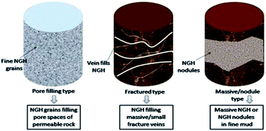

image file: c4ra10248g-p1.tif

Chun-Gang Xu

Chun-Gang Xu, PhD, Research fellow, graduated from Guangzhou Institute of Energy Converse, Chinese Academy Science. From 2008 to now, he has worked at the Center of Gas Hydrate Research in the Guangzhou Institute of Energy Conversion, Chinese Academy of Sciences, as a senior engineer. He has undertaken more than 10 projects in China including the “National High Technology Research and Development Program of China (863 Program)”, the “National Natural Science Foundation of China”, CAS Knowledge Innovation Program, the “Natural and Science Foundation of Guangdong”, and “Science and Technology Planning Project of Guangdong Province”, etc. He mainly works on the study of hydrate-based CO2 capture from flue and fuel gases.

image file: c4ra10248g-p2.tif

Xiao-Sen Li

Xiao-Sen Li, Editorial Board member of Global Journal of Physical Chemistry, graduated from Tsinghua University in 2000. He then worked at University of Alberta and University of British Columbia. In 2005, he was awarded the “Hundred Talents Program” of the Chinese Academy of Sciences (CAS). Since then he has worked at the Center of Gas Hydrate Research, Guangzhou Institute of Energy Conversion, CAS as a chief scientist and professor and as an academic leader for the CAS Innovation Program. He has undertaken over 30 projects internationally. He researches the equilibrium and kinetics, production, and utilization and application of gas hydrates, with over 120 academic papers and 3 books published, 26 patents (14 have been authorized) and 1 Computer Software Copyright Registration.


Introduction

Due to the consumption of fossil fuels, an alternative energy source is necessary for the world’s continuous development. Natural gas hydrates (NGHs) are regarded as a potential future resource due to their wide existence in ocean floor and permafrost zones, containing approximately carbon of 10[thin space (1/6-em)]000 Gt.1–5 Presently, the explored NGH reservoirs in the oceanic floor are mainly distributed in Japan, India, the Gulf of Mexico, the Bering Strait, the South China Sea, Korea, and Trinidad and Tobago, and those in the permafrost are mainly distributed in Alaska (USA), the Mackenzie Delta (CAN), the Qinghai-Tibet plateau (China) and Siberia (RUS).6 NGHs are non-stoichiometric crystalline compounds, which consist of natural gas molecules and water molecules in high pressure and low temperature conditions.7 The characteristics of NGHs change with the conditions of the NGH reservoir. The basis of the production of natural gas from NGHs is shifting the equilibrium conditions of the NGH reservoir to the NGH dissociation side,8,9 therefore, a number of the scientific issues concerning NGH decomposition have been discussed.10–14

NGHs, as a potential energy source for the future, are found in solid form and are not amenable to the conventional gas and oil production techniques.15 Thus, before the experimental production simulation, researchers still need to do a large amount of numerical simulation work to predetermine or evaluate the feasibility of gas production from NGHs. The key parameters for preparing a numerical simulation include the properties of the reservoir, boundary conditions, and the structure of the NGH. NGH deposits are mainly divided into three classes.16–18 Class 1 contains a hydrate-bearing layer (HBL) and a two-phase fluid zone which is underlying the HBL. Free gas can be found in the two-fluid zone. Class 2 is composed of a HBL and a mobile water zone which is underlying the HBL. Class 3 contains only a HBL with no underlying zone of mobile fluids. Additionally, there is a fourth classification, Class 4. Class 4 only disperses in the oceanic floor with low hydrate saturation and lacks confining geologic strata.19 The different NGH deposits mean different reservoirs with various properties, resulting in different boundary conditions for either numerical simulation or experimental production. Presently, the most popular production approaches involve depressurization, heating (thermal stimulation), chemical inhibition injection, and their combinations.20

Depressurization involves lowering the inside pressure of the well, promoting the NGH to dissociate, and further lowering the pressure in the free-gas zone rapidly beneath that in the hydrate stability zone, decomposing the hydrates in the stability zone. An experimental simulation production study is conducted in a confined reservoir, and a depressurizing downhole well is drilled in the reservoir. During the depressurization, the decomposed natural gases flow from the hydrate deposits to the well.21 However, NGH dissociation is an endothermic process, which results in a decrease of the temperature and even prevents the NGH from continuously dissociating. Thus, it is important to maintain the temperature using a heat supply from outside or heat exchange during the depressurization. Additionally, gas production from NGHs is accompanied by a large production of water, and the spread or flow of the water must impact on the properties of the system and the natural gas recovery.

Thermal stimulation involves injecting a heat source (e.g., hot water, steam) into the hydrate stability zone to raise its temperature and decompose the NGH. The decomposed natural gases mixed with the hot water or steam return to the surface. For the thermal stimulation, the diffusion of the heat sources in the hydrate zone and the heat exchange efficiency are important.22 However, compared to depressurization, thermal stimulation is quite expensive because of the consumption of a large amount of heat energy. Researchers are seeking a new and economical integrated method which combines depressurization with thermal simulation.23–25

The method of chemical inhibition injection seeks to shift the NGH equilibrium conditions by injecting a chemical inhibitor into the NGH reservoir. The popular chemical inhibitors include alcohol (e.g., methanol, glycol) and electrolyte (e.g., calcium chloride – CaCl2).26–30 The inhibitor is injected directly from the surface down to the NGH layers. However, because the chemical inhibition contaminates the environment and the production rate by the method is slow, the method does not attract more attention than CO2 injection. Presently, projects of injecting CO2 into NGH deposits to replace the methane from the NGHs are extensively being studied.31–34 Since the thermodynamic feasibility of the replacement between CO2 and methane (CH4) in hydrates was proved,35–39 various studies on the replacement of methane hydrate with CO2 have been or are being conducted, including molecular dynamics simulations,40–43 kinetic models,36,44 and experimental replacement.45–51 Relative to the other methods, the method of replacement of methane from NGHs with CO2 does not only seek to produce methane from the NGHs but also to sequestrate CO2 directly. However, the low replacement rate and low CH4 recovery illustrate that these studies are still in their infancy, and a lot of work needs to be done in the future.

Of all these production technologies, depressurization is considered as the simplest one, and it is especially suitable for the zones where free-gas is trapped beneath the methane hydrates. The method of depressurization combined with heating seems to be the most practical. Currently, many countries including the USA, Canada, Japan, Russia, China, India, etc., have proposed projects on drilling and producing NGHs. In 2002, researchers first carried out Onshore Production Tests in the Mallik test site in the Mackenzie Delta, which is located in the Northwest Territories of Canada. In the Offshore Production Tests, the “hot water circulation method” – a method of heating – was adopted for producing methane gas from NGHs. It was the first time that methane gas was produced successfully from methane hydrate layers. Five years later, depressurization was used for producing methane from NGHs at the same site in 2007 and 2008. The tests demonstrated that depressurization is more effective for producing NGHs relative to heat stimulation.52 In 2013, Japan said it successfully extracted natural gas from frozen methane hydrate off its central coast (Nankai trough) by depressurization, and it was the first offshore production.53

However, there is no large-scale industrial production anywhere in the world. In fact, methane production from NGHs is still a long-term research work. In this paper, the reported studies are reviewed systematically and comprehensively from the aspects of the properties of hydrate deposits, numerical simulation production, experimental simulation production and molecular dynamics simulation, etc. Also, we hope to highlight the focus of future research through this paper.

Classification of NGH reservoirs

NGH is formed if natural gas and water coexist in the low temperature and high pressure conditions that satisfy NGH stability. According to the differences of the places and the forms of gas and water existing, NGH deposits are defined as three types (as shown in Fig. 1): pore filling type NGH reservoir, naturally fractured type NGH reservoir and massive/nodule NGH reservoir.16Fig. 2 shows real NGH deposits with different morphologies which were drilled out in different areas.54 In the first type, NGH, like a typical accumulation of conventional oil and gas, is contained in the pore spaces of porous media such as sandstone and carbonate rocks. In the second type, NGH is contained in fractures or veins. In the third type, NGH is generally distributed in fine grained muds in the form of lumps due to its formation on the shallow layer of the sea floor. Among all the presently proven NGH reservoirs, the Mallik NGH reservoirs, Mt. Elbert NGH reservoirs (located in Alaska North Slope) and reservoirs located in the Eastern Nankai Trough offshore Japan were defined as the first type, named as pore filling NGH reservoirs.55–57 By analyzing the data obtained from exploratory drilling, coring and well logging, the characteristics of the Mt. Elbert NGH reservoirs were systematically studied. The Eastern Nankai reservoirs were confirmed by 2D/3D seismic together with a series of exploratory drillings. Reservoirs of the second type, named as fracture NGH reservoirs, were discovered mainly offshore in India and South Korea. Reservoirs of the third type, described as massive/nodule NGH reservoirs, have been found in the Gulf of Mexico and Japan Sea. However, relative to the first type of reservoirs, producing gas is quite hard from both the second and third types of NGH reservoirs, probably due to the relatively low energy efficiency. Fig. 3 shows a resource pyramid proposed by Boswell and Collett in 2006.58 The resource pyramid displays the relative size and feasibility for production of the different categories of NGH occurrences in nature. Therefore, as seen from Fig. 3, as energy resources, the levels of the second and third type reservoirs are much lower than that of the first type of reservoir.58 Thus, the following content focuses on discussions of the pore filling type NGHs.
image file: c4ra10248g-f1.tif
Fig. 1 Type of NGH reservoir.60

image file: c4ra10248g-f2.tif
Fig. 2 NGH deposits in the world.54

image file: c4ra10248g-f3.tif
Fig. 3 The hydrate resource pyramid modified from Boswell and Collett (2006).59

According to the conditions of the existence of the NGH, the free gas and the free water, there are four classes of pore filling type reservoirs. Class 1 reservoirs comprise two zones: the upper zone is the hydrate stratum, and the underlying zone is a two-phase fluid zone with free gas. Because the hydrate saturation in the pore spaces is relative large, the effective permeability of the hydrate stratum thereby is relatively low. In this class, the bottom of the hydrate stability zone generally is the bottom of the hydrate stratum. Class 1 is the most suitable one for methane exploitation because the hydrate thermodynamic is close to the hydrate equilibrium, i.e., it needs quite few changes of pressure and temperature to induce the dissociation of the NGH. The Messoyakha Field in Russia and the Sagavanirktok Formation in Alaska are typical examples of Class 1 deposits. Class 2 reservoirs also comprise two zones: a hydrate-bearing stratum and a zone of mobile water with no free gas which covers the hydrate-bearing stratum. Class 3 can be seen as a single zone of the hydrate stratum and its characteristic is that no underlying mobile fluid zone exists. Most of the NGH deposits discovered in the Eastern Nankai Trough, Mallik site and Mt. Elbert are categorized as Class 3, and a part of the reservoirs in the Eastern Nankai Trough and the Mallik site are Class 2. Different from the above three Class deposits, Class 4 deposits are widespread and not bound by confining strata, and they mainly appear as nodules with low saturation over large areas. Moridis et al.9 defined Class 4 deposits as those NGH deposits containing NGH sparsely in mud layers. Currently, the Class 4 deposits are generally not regarded as a target for exploitation. A schematic covering Class 1–3 types of NGH deposits is shown in Fig. 4. In Classes 2 and 3, the entire hydrate interval might be well within the hydrate stability zone, that is to say, the bottom of the hydrate interval does not mark the bottom of the hydrate stability zone. Relative to the NGH deposits of Class 1, the desirability of Class 2 and 3 accumulations as gas production targets is not well defined, and it could be affected by many factors such as thermodynamic proximity to the hydration equilibrium, initial conditions of temperature, pressure and boundary, environmental concerns and economic considerations.59


image file: c4ra10248g-f4.tif
Fig. 4 Schematic covering Class 1–3 types of NGH deposits.60

For the four types of NGH reservoirs, the NGH dissociation and gas production are influenced by the parameters of the sand layers, sandstone and carbonate rocks.60,61 The parameters including depth, thickness, porosity, permeability, NGH saturation, thermodynamic conductivity, and initial conditions of temperature, pressure and boundary, are essential to evaluate the gas producibility from the NGH reservoirs. Besides the parameters, heterogeneities of the NGH reservoir, including spatial variations of either the permeability or NGH saturation and distribution of impermeable layers, also play important roles for gas production from the NGH reservoir. In the pore filling type NGH reservoir, for example, the properties of the types of reservoirs range widely, as shown in Table 1.60

Table 1 Properties of pore filling type NGH deposit ranges
Item Range Unit
Reservoir depth 1000–1500 m
Reservoir thickness A few ∼ over 100 m
Porosity A few ∼ over 40 %
Absolute permeability A few ∼ over 1000 mD
Initial effective permeability 0 ∼ over 10 mD
NGH saturation 0 ∼ over 90 %
Total thermal conductivity 2–4 W mK−1
Initial pressure 5–15 MPa
Initial temperature 3–15 °C


Gas production methods

For a certain NGH reservoir, the initial temperature and pressure are in the NGH stable conditions. To dissociate NGH and produce gas from the NGH reservoir, it is necessary to shift the initial temperature and pressure to the NGH dissociation side. As depicted in Fig. 5, depressurization decreases a NGH reservoir pressure below the three-phase (gas–NGH–water) equilibrium pressure, while thermal injection increases the temperature above the three-phase equilibrium temperature. Inhibitor injection shifts the three-phase equilibrium conditions to high pressure and low temperature and, thereby, moves the reservoir conditions to the NGH dissociation side. Presently, new methods combining the above three basic methods are proposed to enhance gas production from a NGH reservoir. Besides, several other methods such as CO2 injection, electrical heating and irradiation by ultrasonic waves have also been investigated for NGH dissociation and gas production (Table 2).62–64Fig. 6 shows a schematic of the three main gas production methods, and in the figure, pictures (a), (b) and (c) are depressurization, hot injection and inhibitor injection, respectively. All these methods are briefly described below.
image file: c4ra10248g-f5.tif
Fig. 5 Principle of NGH dissociation.60

image file: c4ra10248g-f6.tif
Fig. 6 Schematic of the three main gas production methods.60,208,209

image file: c4ra10248g-f7.tif
Fig. 7 Schematic of phases and components in a kinetic model.

image file: c4ra10248g-f8.tif
Fig. 8 Outline of international gas hydrate research in the world.204
Table 2 List of the studies of methane production from NGHs by different methods
Item Method Literature Subject
1 Depressurization Li et al.210 Depressurization induced gas production from hydrate deposits with low gas saturation in a pilot-scale hydrate simulator
2 Depressurization Shahbazi et al.211 Behavior of depressurization in type III hydrate reservoirs
3 Depressurization Chejara et al.212 Simulations of long term methane hydrate dissociation by pressure reduction using an extended RetrasoCodeBright simulator
4 Depressurization combined with heating Falser et al.213 Increased gas production from hydrates by combining depressurization with heating of the wellbore
5 Depressurization combined with heating Feng et al.214 Evolution of hydrate dissociation by Warm Brine Stimulation combined depressurization in the South China Sea
6 Thermal stimulation Fitzgerald & Castaldi215 Thermal stimulation based methane production from hydrate bearing quartz sediment
7 Depressurization Haligva et al.13 Recovery of methane from a variable-volume bed of silica sand/hydrate by depressurization
8 Depressurization Ji et al.216 Natural gas production from hydrate decomposition by depressurization
9 Depressurization Jiang et al.217 Sensitivity analysis of gas production from Class 1 hydrate reservoir by depressurization
10 Thermal stimulation Kawamura et al.218 Experimental study on steam injection method using methane hydrate core samples
11 Inhibitor or steam injection combined with depressurization Kawamura et al.219 Dissociation behavior of hydrate core sample using thermodynamic inhibitor – part 3. Inhibitor or steam injection combined with depressurization and high-concentration inhibitor injection
12 Inhibitor injection Kawamura et al.220 Dissociation experiment of hydrate core sample using thermodynamic inhibitors – part 2
13 Depressurization Kim et al.221 Depressurization experiment of pressure cores from the central Ulleung Basin, East Sea: insights into gas chemistry
14 Depressurization Konno et al.222 Key factors for depressurization-induced gas production from oceanic methane hydrates
15 Depressurization Lee et al.74 An experimental study on the productivity of dissociated gas from gas hydrate by depressurization scheme
16 Inhibitor combined with depressurization Li et al.24 Gas production from methane hydrate in a pilot-scale hydrate simulator using the huff and puff method by experimental and numerical studies
17 Depressurization Li et al.223 Experimental and numerical studies on gas production from methane hydrate in porous media by depressurization in pilot-scale hydrate simulator
18 Steam injection combined with depressurization Li et al.96 Production behavior of methane hydrate in porous media using huff and puff method in a novel three-dimensional simulator
19 Steam injection combined with depressurization Li et al.224 The use of dual horizontal wells in gas production from hydrate accumulations
20 Steam injection combined with depressurization Li et al.225 The use of huff and puff method in a single horizontal well in gas production from marine gas hydrate deposits in the Shenhu area of South China Sea
21 Steam injection Li et al.226 Experimental investigations into gas production behaviors from methane hydrate with different methods in a cubic hydrate simulator
22 Depressurization combined with heat injection Li et al.227 Experimental study on gas production from methane hydrate in porous media by SAGD method
23 Depressurization combined with heat injection Li et al.97 Experimental study on gas production from methane hydrate in porous media by huff and puff method in pilot-scale hydrate simulator
24 Depressurization Li et al. Experimental investigation into gas production from methane hydrate in sediment by depressurization in a novel pilot-scale hydrate simulator
25 Depressurization Li et al.84 Experimental investigation into the production behavior of methane hydrate in porous sediment by depressurization with a novel three-dimensional cubic hydrate simulator
26 Depressurization, inhibitor, heat injection Liu et al.228 Experimental simulation of the exploitation of natural gas hydrate
27 Depressurization and combined method Liu et al.229 Experimental study of gas production from methane hydrate by depressurization and combination method under different hydrate saturations
28 Depressurization Moridis et al.19 Gas production potential of disperse low-saturation hydrate accumulations in oceanic sediments
29 Solar energy heating and depressurization Ning et al.230 A method to use solar energy for the production of gas from marine hydrate-bearing sediments: a case study on the Shenhu area
30 Depressurization Oyama et al.231 Dependence of depressurization-induced dissociation of methane hydrate bearing laboratory cores on heat transfer
31 Depressurization Oyama et al.232 Depressurized dissociation of methane-hydrate-bearing natural cores with low permeability
32 Hot water injection Phirani et al.233 Warm water flooding of confined gas hydrate reservoirs
33 Depressurization Sakamoto et al.234 Field scale simulation for the effect of relative permeability on dissociation and gas production behavior during depressurization process of methane hydrate in marine sediments
34 Thermal stimulation Schicks et al.235 A counter-current heat-exchange reactor for the thermal stimulation of hydrate-bearing sediments
35 Depressurization Su et al.236 Evaluation on gas production potential from laminar hydrate deposits in Shenhu area of South China Sea through depressurization using vertical wells
36 Steam injection Su et al.237 A huff-and-puff production of gas hydrate deposits in Shenhu area of South China Sea through a vertical well
37 Depressurization Sun et al.78 1-D modeling of hydrate depressurization in porous media
38 Depressurization Sung et al.238 Experimental investigation of production behaviors of methane hydrate saturated in porous rock
39 Inhibitor injection Sung et al.239 Numerical study for production performances of a methane hydrate reservoir stimulated by inhibitor injection
40 Depressurization Tang et al.72 Control mechanisms for gas hydrate production by depressurization in different scale hydrate reservoirs
41 Depressurization Waite et al.240 Physical property changes in hydrate-bearing sediment due to depressurization and subsequent repressurization
42 Depressurization and heating Wu et al.241 Effect of rapidly depressurizing and rising temperature on methane hydrate dissociation
43 Depressurization Xiong et al.242 Experimental study on methane hydrate dissociation by depressurization in porous sediments
44 Depressurization Yamamoto et al.243 Gas hydrate production from geological formations as transport phenomena
45 Molecular dynamics simulation/depressurization Yan et al. Molecular dynamics simulation of methane hydrate dissociation by depressurisation
46 Numerical simulation/depressurization Yang et al.244 Numerical simulation of Class 3 hydrate reservoirs exploiting using horizontal well by depressurization and thermal co-stimulation
47 Depressurization Yang et al.83 A three-dimensional study on the formation and dissociation of methane hydrate in porous sediment by depressurization
48 Hot-water cyclic injection Yang et al.92 Experimental study on gas production from methane hydrate-bearing sand by hot-water cyclic injection
49 Numerical simulation/depressurization Yu et al.245 Numerical simulation on natural gas production from gas hydrate dissociation by depressurization
50 CO2 replacement Yuan et al.62 Methane recovery from natural gas hydrate in porous sediment using pressurized liquid CO2
51 Heat and inhibitor injection Yuan et al.246 Experimental study of gas production from hydrate dissociation with continuous injection mode using a three-dimensional quiescent reactor
52 CO2 replacement Yuan et al.247 Recovery of methane from hydrate reservoir with gaseous carbon dioxide using a three-dimensional middle-size reactor
53 Mathematical model and simulation/depressurization Zhao et al.248 Mathematical model and simulation of gas hydrate reservoir decomposition by depressurization
54 Numerical simulation/depressurization Zhao et al.249 Numerical simulation and analysis of water phase effect on methane hydrate dissociation by depressurization
55 Numerical simulation/depressurization Zhao et al.250 Numerical simulation of gas production from hydrate deposits using a single vertical well by depressurization in the Qilian Mountain permafrost, Qinghai-Tibet Plateau, China
56 Depressurization Zhao et al.251 Analysis for temperature and pressure fields in process of hydrate dissociation by depressurization
57 Numerical simulation/depressurization, inhibitor or heat injection Kurihara et al.98 Prediction of gas productivity from Eastern Nankai trough methane-hydrate reservoirs
58 Numerical simulation/depressurization Liang et al.252 Numerical simulation for laboratory-scale methane hydrate dissociation by depressurization
59 Numerical simulation/depressurization, inhibitor or heat injection Liu et al.253 Numerical simulation of methane production from a methane hydrate formation
60 Depressurization and thermal injection Liu et al.254 Simulation of methane production from hydrates by depressurization and thermal stimulation
61 Numerical simulation/depressurization Moridis17 Numerical studies of gas production from Class 2 and Class 3 hydrate accumulations at the Mallik site, Mackenzie Delta, Canada
62 Numerical simulation/depressurization and thermal stimulation Moridis et al.8 Numerical studies of gas production from several CH4 hydrate zones at the Mallik site, Mackenzie Delta, Canada
63 Numerical simulation/depressurization Myshakin et al.255 Numerical simulations of depressurization-induced gas production from gas hydrate reservoirs at the Walker Ridge 313 site, northern Gulf of Mexico
64 Computational modeling/depressurization Nazridoust & Ahmadi256 Computational modeling of methane hydrate dissociation in a sandstone core
65 CO2 replacement Ors & Sinayuc257 An experimental study on the CO2–CH4 swap process between gaseous CO2 and CH4 hydrate in porous media
66 Depressurization Peters et al.258 Hydrate dissociation in pipelines by two-sided depressurization – experiment and model
67 Numerical simulation/depressurization Ruan et al.259 Numerical simulation of the gas production behavior of hydrate dissociation by depressurization in hydrate-bearing porous medium
68 Numerical simulation/depressurization Ruan et al.260 Numerical simulation of methane production from hydrates induced by different depressurizing approaches
69 Numerical simulation/depressurization Ruan et al.261 Numerical studies of hydrate dissociation and gas production behavior in porous media during depressurization process
70 Numerical simulation/depressurization Sakamoto et al.262 Numerical study on dissociation of methane hydrate and gas production behavior in laboratory-scale experiments for depressurization: part 3-numerical study on estimation of permeability in methane hydrate reservoir
71 Computational modeling/depressurization Sean et al.263 CFD and experimental study on methane hydrate dissociation. Part II. General cases
72 Numerical simulation/CO2 injection White et al.264 Numerical studies of methane production from Class 1 gas hydrate accumulations enhanced with carbon dioxide injection
73 CO2 replacement Jung265 Entrapping CO2, while recovering methane
74 Molecular dynamics simulation/depressurization Yan et al.266 Molecular dynamics simulation of methane hydrate dissociation by depressurization
75 Depressurization Toki et al.267 Methane production and accumulation in the Nankai accretionary prism: results from IODP expeditions 315 and 316
76 CO2 replacement Seo et al.268 Experimental verification of methane replacement in gas hydrates by carbon dioxide
77 CO2 replacement Pohlman et al.269 Methane sources and production in the northern Cascadia margin gas hydrate system
78 Numerical simulation/depressurization Li et al.270 Numerical simulation of gas production from natural gas hydrate using a single horizontal well by depressurization in Qilian Mountain permafrost
79 CO2 replacement Lee et al.271 Thermodynamic and 13C NMR spectroscopic verification of methane–carbon dioxide replacement in natural gas hydrates
80 CO2 replacement Lee et al.272 Quantitative measurement and mechanisms for CH4 production from hydrates with the injection of liquid CO2
81 CO2 replacement Jung et al.273 Properties and phenomena relevant to CH4–CO2 replacement in hydrate-bearing sediments
82 CO2 replacement Espinoza & Santamarina274 P-wave monitoring of hydrate-bearing sand during CH4–CO2 replacement
83 CO2 replacement Deusner et al.275 Methane production from gas hydrate deposits through injection of supercritical CO2
84 Depressurization combined with heat injection Wang et al.94 Experimental investigation into scaling models of methane hydrate reservoir
85 Thermal huff ‘n’ puff Wang et al.276 Experimental study on the hydrate dissociation in porous media by five-spot thermal huff and puff method
86 Numerical simulation/depressurization Temma et al.277 Numerical simulation of gas hydrate dissociation in artificial sediment
87 CO2 replacement Taboada-Serrano et al.278 Multiphase, microdispersion reactor for the continuous production of methane gas hydrate
88 Depressurization Su et al.82 Experimental investigation of methane hydrate decomposition by depressurizing in porous media with 3-dimension device
89 Hot water injection Sasaki et al.279 Gas production system from methane hydrate layers by hot water injection using dual horizontal wells
90 Heat stimulation Sakamoto et al.280 Gas hydrate extraction from marine sediments by heat stimulation method
91 Thermal stimulation Pang et al.89 Methane hydrate dissociation experiment in a middle-sized quiescent reactor using thermal method
92 Depressurization Link et al.281 Methane hydrate research at NETL, research to make methane production from hydrates a reality
93 CO2/CO2–N2 replacement Koh et al.180 Recovery of methane from gas hydrates intercalated within natural sediments using CO2 and a CO2/N2 gas mixture
94 Thermal stimulation Gong et al.282 Simulation experiments on gas production from hydrate-bearing sediments
95 Depressurization Gerami & Pooladi-Darvish283 Predicting gas generation by depressurization of gas hydrates where the sharp-interface assumption is not valid
96 Mathematical modeling and numerical simulation Gamwo & Liu196 Mathematical modeling and numerical simulation of methane production in a hydrate reservoir
97 Thermal stimulation Castaldi284 Down-hole combustion method for gas production from methane hydrates
98 Depressurization Ahmadi et al.21 Production of natural gas from methane hydrate by a constant downhole pressure well
99 Computation modeling Ahmadi et al.285 Natural gas production from hydrate dissociation: an axisymmetric model
100 Numerical simulation Ahmadi et al.286 Numerical solution for natural gas production from methane hydrate dissociation
101 CO2 replacement Uchida et al.287 Replacing methane with CO2 in clathrate hydrate: observations using Raman spectroscopy
102 CO2 replacement Zhou et al.49 Replacement of methane from quartz sand-bearing hydrate with carbon dioxide-in-water emulsion
103 CO2 replacement Zhou et al.35 Determination of appropriate condition on replacing methane from hydrate with carbon dioxide
104 CO2 replacement Yoon et al.288 Transformation of methane hydrate to carbon dioxide hydrate: in situ Raman spectroscopic observations
105 CO2 replacement Yezdimer et al.289 Determination of the Gibbs free energy of gas replacement in SI clathrate hydrates by molecular simulation
106 CO2 replacement Voronov et al.290 Experimental study of methane replacement in gas hydrate by carbon dioxide
107 Molecular dynamics simulation/replacement Tung et al.40 In situ methane recovery and carbon dioxide sequestration in methane hydrates: a molecular dynamics simulation study
108 CO2 replacement Qi & Zhang291 MD simulation of CO2–CH4 mixed hydrate on crystal structure and stability
109 Molecular dynamics simulation/replacement Qi et al.181 Molecular dynamics simulation of replacement of CH4 in hydrate with CO2
110 CO2 replacement Ota et al.136 Macro and microscopic CH4–CO2 replacement in CH4 hydrate under pressurized CO2
111 CO2 replacement Ota et al.44 Replacement of CH4 in the hydrate by use of liquid CO2
112 CO2 replacement Ota et al.38 Methane recovery from methane hydrate using pressurized CO2
113 CO2 replacement Martos-Villa et al.292 Characterization of CO2 and mixed methane/CO2 hydrates intercalated in smectites by means of atomistic calculations
114 CO2 replacement Li et al.293 Exploitation of methane in the hydrate by use of carbon dioxide in the presence of sodium chloride
115 CO2 replacement Lee et al.294 Experimental verification of methane–carbon dioxide replacement in natural gas hydrates using a differential scanning calorimeter
116 CO2 replacement Lee et al.295 Replacement of methane hydrate by carbon dioxide: 13C NMR study for studying a limit to the degree of substitution
117 Molecular dynamics simulation/replacement Iwai et al.42 Molecular dynamics simulation of replacement of methane hydrate with carbon dioxide
118 Molecular dynamics simulation/replacement Geng et al.41 Molecular simulation of the potential of methane reoccupation during the replacement of methane hydrate by CO2
119 CO2 replacement Bai et al.296 Replacement mechanism of methane hydrate with carbon dioxide from microsecond molecular dynamics simulations


Depressurization method

For depressurization, the pressure in a bottom hole is first lowered by a vacuum air pump. As the pressure in the bottom hole is lower than the three-phase equilibrium pressure, the NGHs in the reservoir dissociate to release natural gas; then, NGH dissociation starts at regions near the well. With the dissociation of NGH, NGH saturation decreases and the effective permeability to fluid increases dramatically, resulting in the low pressure transferring to a distant region from the well. Thereby, a benign cycle is formed: pressure is lowered in a well → NGH near the well dissociates → permeability increases → low pressure transfers to a distant area from the well → more NGH dissociates → permeability further increases → and so on. By the cycle, the areas of NGH dissociation and gas production hence increase with time. However, because the dissociation of NGH is an endothermic reaction, the reservoir temperature must decrease along with the NGH dissociation. Thus, once the reservoir temperature is lower than or even identical to the three-phase equilibrium temperature corresponding to the reservoir pressure, the NGH dissociation stops, and the gas production hence stops. Therefore, with the depressurization method, the sustainability of gas production depends on the temperature transfer at the interface of the NGH dissociation zone and the NGH zone.

Many researchers have carried out experiments on methane production simulation in the laboratory by the depressurization method. Experimental reactors with different volumes have also been developed, and in the early studies, the volume of most of the adopted reactors was 1 L.65–70 Even recently, small reactors were extensively used in experimental studies.13,71–75 Yousif et al.66 simulated the gas production by depressurization from the hydrates existing in Berea sandstone cores, and from their investigation, the gas production and the position of the hydrate dissociation front were considered as a function of time. In order to prove numerical models of gas hydrate behavior in porous sediments, Kneafsey et al.73,76,77 performed many experiments and obtained plenty of valuable experimental data using a large pressure vessel with inner and outer diameters of 76.2 mm and 89.0 mm, respectively. Besides, using a batch reactor with a volume of 188 mL, Kono et al.71 revealed the methane hydrate dissociation rate somewhat depends on the sediment properties in porous media. To investigate the behavior of hydrate dissociation by depressurization in porous rocks, Lee et al.74 built a set of special apparatus in which the main part was a one-dimensional core holder and the fluid flows in the axial direction. In their experiments, in order to make the samples more close to the naturally occurring sediments in deep sea, the axial pressure and overburden pressure were applied together with the already existing inner pressure of the core sample. In addition, many experiments focused on investigating methane hydrate dissociation were carried out by depressurizing to different pressures and/or at different temperatures.78,79 Our group experimentally investigated the effects of pore size, temperature, and initial formation pressure on the dissociation kinetic behavior of methane hydrates in porous media. In our experiments, the methane production rate and temperature change were also systematically investigated using a one-dimensional cell with about 280 mL.75 The conclusions from the experiments were drawn as, on one hand, either the increase of initial pressure or the increase of the mean pore size or the decrease of the environmental temperature has a positive effect on the methane production rate, or on other hand, the system temperature decreases dramatically during the hydrate dissociation process and then gradually rises to the environmental temperature after it reaches the lowest temperature point. Our conclusion was supported by Haligva et al.13 as they found, by depressurization, the initial rate of methane recovery rate is strongly influenced by the size of silica sand in the process of methane recovery from silica sand/hydrate with a variable-volume.

However, to make the experimental simulation of methane production from NGHs more consistent with the actual situation and to know a more realistic behavior of gas hydrate dissociation, the experimental reactor scale is a crucial factor in laboratory experiments. Recently, some hydrate simulation reactors with large volumes have been developed. American scientists at Oak Ridge National Laboratory designed a Seafloor Process Simulator (SPS) experimental platform with a 72 L reactor to study the gas hydrate dissociation behavior by the depressurization method.80 In addition, Zhou et al.81 developed a set of experimental apparatus with an about 59 L reactor to investigate methane hydrate dissociation behavior. Chen et al.82,83 built a cylindrical experiment device to simulate the behavior of gas hydrate formation and dissociation. The highest operation pressure for the cylindrical reactor with an inner diameter of 300 mm and an effective height of 100 mm reaches 16 MPa. The reactor is separated into two parts by a stainless steel board with many pores and a 3 mm thickness. The steel board can, thereby, separate free gas from porous sediments in the experiments. Sixteen thermal resistances were set to distribute in the reactor for measuring the temperature at different depth and radius. Using the device, Chen et al.82,83 found the gas production rates are quite different with different gas production stages. The gas production rate is fastest at the beginning. Besides, in this stage, the temperature decreases with the decrease of the radius of the reactor. A three-dimensional cubic hydrate simulator (CHS) with an effective volume of 5.8 L was developed by our team to study the gas production behavior of methane hydrate in porous sediments under depressurization.84 75 (25 × 3) temperature measuring points and 36 (12 × 3) resistance measuring points were precisely designed and distributed evenly in the CHS. By using the CHS, the conditions of a hydrate reservoir in the Shenhu Area, South China Sea were simulated. We found the resistances in the hydrate reservoir are strictly influenced by the hydrate dissociation and the flow of the gas and water during the methane production process. In addition, we found the gas production rate, along with the cumulative gas production, increases with the decrease of the pressure. The pressure reduction rate and the heat supplied from the ambient are the two main gating factors for the NGH dissociation. From the scientific simulation viewpoint, the more ideal simulation should be based on the conducted laboratory experiments with a larger reactor to mimic actual field conditions. Nevertheless, to design and develop a reactor with a larger volume is rather difficult in practical operation. Moreover, it is quite hard to ensure the synthesized hydrate samples distribute homogeneously in the larger reactor. A bigger three-dimensional cubic hydrate simulator with a volume of 117.8 L was designed and developed by our team. In the big simulator, which was also called a Pilot-scale Hydrate Simulator (PHS), vertical wells distributing in 9 spots evenly and a horizontal well were designed. Besides, a total of 49 thermometers and resistance ports were evenly distributed in three horizontal layers, respectively. The experimental apparatus schematics and the PHS are shown in Fig. 9 and 10.25 Compared with the results obtained from the experiment with the 5.8 L CHS,84 the experimental results showed the gas production process consists of three periods, including free-gas production, mixed-gas production and gas production. The first and second periods are mainly controlled by the pressure reduction rate while the third period is mainly driven by the heat conduction from the ambient. The duration of gas production with the PHS was approximately 20 times as long as that with the CHS. Besides, the tendency of the system temperature to change with the PHS is the same as that with the CHS, while the water production behavior with the PHS is different from that with the CHS.


image file: c4ra10248g-f9.tif
Fig. 9 Schematic of experimental apparatus with PHS.25

image file: c4ra10248g-f10.tif
Fig. 10 Schematic of layers and well design of PHS.25

The first production tests using the depressurization method in the world were conducted in the Mallik production program in April 2007 and March 2008.57 The tests not only successfully attained methane gas from the NGH reservoir but also revealed that methane recovery highly depends on the reservoir characteristics. Besides, the methane recovery is predicted to be up to 60% even in the favorable case by the tests.

Thermal method

The thermal method involves promoting NGH dissociation by increasing the temperature of the reservoir. Currently, the general thermal method techniques include the thermal stimulation method and the thermal flooding method. The thermal method seeks to increase the temperature in the surrounding regions of a well by ways such as hot water circulation, wellbore heating and hot water huff and puff. For the first way, the hot water is circulated in a wellbore to increase the temperature of the bottom hole; for the second way, the wellbore is heated by a heater installed in the down hole; the third way can be described as injecting hot water or steam into the deposit from a well (huff), then the well is shut-in for a time to transfer the heat to the deposit sufficiently (soak), and then, the gas is produced as well as water from the well (puff). In a fourth way, the temperature increase is caused by injecting the heat from a well and flooding to other wells. The detailed schematic diagram of the thermal method is shown as picture (b) in Fig. 6. For the ways of hot water circulation and wellbore heating, although the NGH dissociation balances the temperature and even the dissociation reduces the temperature in the dissociation region below the three-phase equilibrium temperature, the NGH would dissociate continuously and completely because heat is continuously supplied. However, because the heat is transferred by thermal conduction, the expansion of the dissociation region with relatively high temperature is extremely slow, resulting in a relatively low gas production efficiency. On the contrary, the ways of hot water huff and puff and hot water flooding induce a much faster spread of the heat and hence enlarge the NGH dissociation areas quickly in the conditions of the hot water being injected smoothly. However, because the effective permeability to water is quite low in the presence of NGHs with a high saturation in the initial stage, it is difficult to keep the hot water injection at a high rate. Moreover, the generated natural gas associated with the dissociation of NGH near the injection well could be cooled again in the course of the drastic NGH dissociation and reform NGH with free water in the region, which reduces the permeability and hinders the further injection of hot water.57,60 The advantage of the thermal method is the gas production rate in the whole hydrate decomposition process could be purposely controlled by regulating the injection rate and the amount of heat. Despite this, heat injection as a gas production method is not suitable for methane hydrate exploitation from permafrost regions from the perspective of cost because the thermal characteristics of the hydrate-bearing region limits the heat diffusion in such low ambient temperature and thick permafrost layers in the region.

In 1982, Holder et al.85 carried out a simulation of the gas production from a reservoir containing both gas hydrates and free natural gas. In the simulation, they evaluated the feasibility of the thermal method and considered the thermal method as an effective exploitation technology. In addition, McGuire considered the thermal method as quite an effective exploitation technology for a hydrate reservoir with high permeability and for a Class 2 hydrate reservoir.86 In the past decades, many experimental simulations have been carried out using the thermal method.87–89 By using a one-dimensional experimental apparatus with an internal diameter of 38 mm and a length of 500 mm, the temperature distribution and the flowing characteristics of the water and gas dissociated from hydrates in porous sediments were measured using thermal stimulation by Tang et al.90 From the investigation, they found the hydrate content has a positive effect on the energy ratio while the injection temperature and rate play negative roles. Pang et al.89 carried out a series of experiments to study the kinetics of methane hydrate dissociation at 268.15 K using a closed quiescent middle-sized reactor with an inner diameter of 200 mm and length of 320 mm. They found that both the heat transfer rate and the thermodynamic driving force are the two main governing factors constraining hydrate dissociation in the sealed reactor, and the dissociation rate can be increased by increasing the temperature of the heating water and lowering the dissociating pressure. By injecting as high as 130 °C brine (salinity of 0–24 wt%) into a one-dimensional experimental device filled with porous sediments, our team successfully investigated the gas production behavior from simulated methane hydrates.91 The experiments indicated the whole gas production process includes three stages such as free-gas production, hydrate dissociation, and general gas-reservoir production. With the brine injection, the hydrates gradually dissociate, and synchronously, the temperature decreases. It is important to note that the dissociation duration shortens with the increase of salinity, while the instantaneous hydrate dissociation rate increases. In addition, we considered the thermal efficiency and energy ratio for the hydrate production can be enhanced by injecting hot brine.16

However, as discussed above, the experimental studies were all carried out only in one and two dimensions. Lately, the experimental studies based on three-dimensional simulation were extensively developed. For example, a three-dimensional experimental simulation on gas production from methane hydrate-bearing sand was carried out by Yang et al.92 by the cyclic injection of hot-water. Their experimental results indicated the overall temperature trend increases with hot-water injection but decreases with gas production. The location of the injection/producing well as well as the porosity and permeability of the hydrate samples dominate the temperature distribution and fluctuation in the reactor. The energy efficiency ratio is positively impacted by the saturation of the hydrate-bearing sand and temperature but negatively influenced by the hot-water temperature and well pressure in the case of other conditions being similar. Using the CHS, our team devoted ourselves to investigating the methane hydrate production behavior in porous sediments by thermal stimulation with a five-spot well system.93 From the investigation, it was found that the boundary of the hydrate decomposition gradually expands from the center to the surroundings, and eventually expands to the whole hydrate field. Heat conduction plays a more significant role than convection from the heat diffusion. The increase of the hot water injection rate plays a positive role of accelerating the hydrate decomposition and then shortening the gas production time and reducing water production. It was also found that the higher the change of the hot water injection rate (Rinj), the higher the average production rate and the lower the energy efficiency, although the Rinj has little influence on the final gas recovery. Based on the experiments with the CHS, we carried out more experiments with a scale-up reactor which was mentioned as the PHS.94 The experimental conditions were designed by a set of scaling criteria for a gas hydrate reservoir. By the comparison of the experiments with the CHS with the experiment with the PHS, we found, on one hand, the gas and water production behaviors are similar and, on the other hand, the energy efficiencies for different processes of hydrate decomposition according with the scaling criteria, which were proven through the experimental results, are identical. And more importantly, the scaling law regulated by the result of the experiments was used for predicting the real-scale hydrate production behavior. For example, in a real-scale hydrate reservoir with the size of 36 m × 36 m × 36 m, methane of 1.168 × 10⁶ m3 in STP is produced after 13.9 days of hydrate production, the gas recovery is 0.73 and the final energy efficiency is 9.5. Beside this work, we also carried out thermal huff and puff experiments using the CHS and PHS.23,24,95–97 Through the experiments, the injection temperature, as well as the pressure, resistance ratio and other parameters were systematically investigated to achieve a series of rules of the parameters during the thermal simulation gas production process. The injected heat first spreads out from the point of injection, then eventually forms a heat flux face. The heat face enlarges with the increase of the number of huff and puff cycles until it reaches the largest. Similar to the results obtained from the one and/or two dimensional experiments, the hydrate dissociation process was also proved as an ablative process of a moving boundary on a three-dimensional level. In addition, the sensitivities of the hydrate dissociation to the initial hydrate saturation, injection time and initial temperature of the hot water were investigated systematically.96 The sensitivity analysis indicated that the gas production depends on the initial hydrate saturation, the temperature and the hot water injection rate. From the experiments carried out in the PHS, the thermal diffusion is limited around the well if the hot water injection rate is fixed, and the depressurization is more advantageous to the gas production relative to the thermal stimulation.97 Besides, the experimental results also indicated with the increase of the hot water injection, the gas production efficiency increases, though the efficiency increase is quite small because it is also adversely impacted by the stronger pressurization.

The production test using the hot water circulation method was first conducted at the Mallik site in Canada in 2002. However, since the energy supplied in the thermal method is quite large, the applicability of the method is disputed from the viewpoint of energy efficiency. Recently, scientists generally agree to apply the thermal method as a secondary recovery method after dissociating the NGH to some extent by depressurization and making paths for water movement.98

Inhibitor injection method

For the inhibitor injection method, hydration inhibitors such as methanol, ethanol, brine, electrolyte solutions, salt and alcohol are injected into a reservoir, shifting the three-phase equilibrium conditions to the low temperature and high pressure side, in which the NGH automatically dissociates.99 However, the shift magnitude is limited and the inhibitor injection method alone could not lead to significant NGH dissociation. Besides, it is difficult to smoothly inject the inhibitor into a reservoir because of the quite low initial effective permeability to water. Therefore, the inhibitors are generally injected together with hot water by the ways of hot water huff ‘n’ puff or hot water flooding to improve the energy efficiency. Furthermore, the issues of the dilution/dispersion of inhibitors and high cost also limit the application of the inhibitor injection method in gas production.

In addition, the thermodynamic inhibitors can lower the activity of water, making the hydrate formation conditions harsher. Therefore, the thermodynamic inhibitors are used to promote the hydrate dissociation and enhance the gas yield in the process of methane production from the hydrate reservoir. Many valuable studies have been reported on investigations into the gas production behavior by the inhibitor injection method.99–131 Through the studies, the hydrate formation equilibrium conditions as well as gas hydrate formation/dissociation behaviors in the presence of inhibitors have been achieved systematically. For volatile inhibitors, Katz et al.132 found the inhibiting effect reduces with the increase of the volatility of the inhibitors. Beside the volatility, the operating pressure also greatly influences the inhibitor effect. Makogon133 found, with the increase of pressure, the inhibiting effect reduced first to a minimum, then increased slightly when an electrolyte solution (CaCl2) was used as the inhibitor. Sira et al.125 used methanol and ethylene glycol as inhibitors to investigate the hydrate dissociation and found the hydrate dissociation rate is controlled by inhibitor concentration, injection rate, interfacial area between the hydrate and the inhibitor as well as pressure and temperature. Fan et al.128 injected 10–30 wt% ethylene glycol into a 3.5 L reactor to investigate the effect of ethylene glycol on methane hydrate dissociation, and they found the hydrate dissociation rate depends on the concentration and the flow rate of ethylene glycol. Similar results were obtained by Li et al.99 They injected ethylene glycol into a one-dimensional device to investigate the gas production behavior from methane hydrate in porous sediments, and found the production efficiency is affected by the concentration of the ethylene glycol and the injection rate. The highest efficiency was achieved when the concentration of the ethylene glycol was 60 wt%. Yuan et al.131 injected ethylene glycol into a three-dimensional apparatus to investigate the gas production behavior from methane-hydrate-bearing sands. They found there is an optimal mass ratio of ethylene glycol to initial water to obtain a maximum gas production ratio. In addition, they found that the concentration of ethylene glycol is positive to either gas production or gas production efficiency, but the gas production efficiency decreases with the increase of the EG quantity.

However, as mentioned above, the inhibitor injection method has never been used in a field test, not only because the inhibitors are expensive and unfriendly to the environment, but also the diffusion of the inhibitors is hindered by the low permeability of hydrate-bearing sediments.

Other methods

Other than the above three basic methods, there are several new methods, which have been investigated for producing methane gas from NGHs in the laboratory. Like the basic methods, the new methods are also based on shifting the gas–water–NGH three-phase equilibrium conditions to the NGH dissociation region. The new methods include gas replacement, ultrasonic wave irradiation, electrical heating and CO2 injection. Gas replacement is injecting other gas components (e.g. CO2) into a NGH reservoir to displace methane. Because CO2 hydrate is formed more easily relative to NGH in the initial methane–water–NGH equilibrium conditions, replacing CH4 with CO2 in the hydrates is feasible.35–38 Furthermore, CO2 hydrate formation is an exothermal reaction, and the reaction heat further promotes the NGH dissociation after it transfers to the internal NGH deposits by heat conductivity. The ultrasonic wave irradiation method can be briefly described as promoting the NGH to dissociate with the vibration of irradiation waves.134 Electrical heating is used to increase the reservoir temperature by transmitting the electrical energy to a reservoir through electrical probes.135 Currently, the method of electrical heating is successfully used for heavy oil recovery from crude oil. Since CO2 hydrate is the preferred hydrate formed below 10 °C relative to CH4 hydrate at pressure lower than 6.5 MPa CO2 is feasible to spontaneously replace CH4 in the hydrate without energy introduction.35,38,44,136 And, the method is beneficial because it offers not only long term storage of CO2 but also methane production without dissociating the hydrate.137,138 CO2 injection methods mainly include micro-emulsion containing CO2 injection, dissolved CO2 injection and pure CO2 liquid injection.139 CO2 injection can shorten the gas production time and reduce the quantity of water produced during the production process. However, it also brings potentially detrimental effects to deep-sea fish due to the permanence of the injected CO2 changing the pH of the hydrate-bearing region.140

Among the methods, gas replacement, especially CO2 replacement, is now studied extensively because of its functions not only in producing CH4 from NGH but also in sequestrating CO2 directly into the sea floor in the form of CO2 hydrate. The studies of CO2–CH4 hydrate replacement include thermodynamics, kinetics, molecular dynamics (MD) simulation and experimental simulation. Dissociation enthalpies of the CH4 hydrate and CO2 hydrate under different conditions of temperature and pressure are systematically obtained through different equations (such as the Clapeyron equation, modified Clapeyron equation, Clausius–Clapeyron equation (C–C eq.), modified C–C eq., thermodynamics equation) and ways based on the experimental equilibrium data (e.g., Calvet heat-flow calorimeter, and Calvet heat-flow differential scanning calorimeter).141–153 Under the conditions of 273.15 K and 3.25 MPa, the Gibbs free energy (ΔG) of the reaction of CH4 replacement by CO2 in hydrates is about −3.49 kJ mol−1, which means the reaction of CO2 replacing CH4 from the hydrate is a spontaneous reaction.38,154 The kinetics of CO2–CH4 replacement has also been extensively studied. In order to qualify and quantify the hydrate formation and dissociation kinetics, many analytical techniques have been proposed, including material balance (MB),155–164 X-ray diffraction (XRD),163,165 neutron diffraction,166 Raman,167–169 nuclear magnetic resonance (NMR),170–174 magnetic resonance imaging (MRI),175–177 and particle size analysis (PSA).157,178,179

At present, two big problems block the application of CO2 replacement in producing CH4 from a NGH reservoir. On one hand, the micro-mechanism of the replacement is still not proven; on the other hand, the CH4 recovery rate and CH4 replacement efficiency are seriously affected by CO2 diffusion in the NGH reservoir.180 In fact, researchers have still not confirmed the details of the replacement process. Does the methane hydrate firstly dissociate and the methane is released from the destructive methane hydrate cavities, followed by the formation of the carbon dioxide hydrate? Or do the CO2 molecules directly replace the CH4 molecules under the condition of keeping the hydrate structure stable? No one has a clear answer. For the governing factor of the CO2–CH4 replacement rate and efficiency, the mainstream view focuses on the kinetics of methane hydrate dissociation and carbon dioxide hydrate formation, especially on the diffusion of CH4 and/or CO2 molecules in the hydrates. However, since the governing factor of the diffusion of gas molecules in the hydrates has been confirmed, researchers have still not proposed any solutions. Thus, the application of CO2–CH4 replacement in producing CH4 from NGH reservoirs still has a long way to go.

Molecule dynamics (MD) simulation is one powerful tool to provide a molecular level understanding of microscopic mechanisms. Geng et al.41 investigated the potential of methane reoccupation during the replacement of methane hydrate by CO2 by the use of MD simulation. Tung et al.40 and Qi et al.181 investigated the microscopic mechanism of CH4 replacement by CO2 in the hydrate by the use of MD simulations. The force field models of TIP4P-Ew182 for water, OPLS-AA183 for methane and EPM2 (ref. 184) for CO2 were adopted in the two studies. Tung et al. constructed a two-phase model by combining CO2 liquid with methane hydrate. In the model, the liquid CO2 phase was actually composed of a total of 320 CO2 molecules, and the methane hydrate phase was set as a series of sI hydrates with normal 6 × 2 × 2 unit cells in which all cavities were filled with CH4 molecules, i.e., a unit cell consists of 1104 H2O molecules and 204 CH4 molecules. The initial size of the model was 114.00 Å × 23.74 Å × 23.74 Å. In Qi et al.’s simulation, 336 three-site CO2 molecules composed the initial gas phase, and the hydrate phase consisted of a 6 × 2 × 2 unit cell of sI hydrate with 2944 water molecules and 512 CH4 molecules. We generally consider that the mechanism of the CO2–CH4 replacement in the hydrate should be stable under certain conditions. Tung et al.40 found that replacement might occur by two ways: one was direct replacement between the CH4 and CO2 molecules; the other involved a transient in which CH4 and CO2 molecules co-occupied one cavity. Therefore, through the simulation, they considered that simultaneously recovering methane from methane hydrate and sequestering CO2 in the solid phase was possible with suitable operation conditions without much change in the geological stability. But, Qi et al.’s181 study indicated the replacement process might be described as: the hydrate cages break first, then CH4 molecules run out of the cages and, at the same time, CO2 molecules enter into the void cages and form CO2 hydrates. They also consider that it is necessary to make the hydrate melt one time or increase the interface area to speed up the replacement. It’s obvious that the results obtained from the two simulations are not consistent with each other. It is difficult to attribute the different results to the difference of the initial simulation systems in the two simulations, i.e., the setup of the initial simulation system should not be the reason for the different results. Thus, what we can suggest is that, till now, the micro-mechanism of CO2–CH4 replacement in the hydrate is still not clear, and researchers should further investigate how to use MD simulation to draw a consistent conclusion.

Numerical simulations and field production tests

Numerical simulations

Numerical simulation is utilized to assess the hydrate production potential for various NGH deposits with different production methods, which were mentioned above, and predict the complex system behaviors. It gives specific data for the design of laboratory and field experiments. Over the past 10 years, numerical simulation has been well developed based on the improved sources of code availability. Currently, there are several numerical models that can simulate the system behavior in NGH deposits. The most commonly used simulators are shown as follows:

(a) The Hydrosim simulator, which was developed at the University of Calgary.185

(b) The MH 21 code, developed by a team in which the group members come from the Japan Oil Engineering Company, the National institute for Advanced Industrial Science and Technology, and the University of Tokyo.186

(c) The STOMP-HYD code, which was developed at the Pacific Northwest National Laboratory.187

(d) A hydrate-specific variant of the commercial simulator CMG-STARS.188

(e) The TOUGH + HYDRATE code, and its earlier version.189,190

These simulators are based on the consideration of both fluid flow and heat transfer while the solid phase is assumed to be immobile. There are other simulators. Kimoto et al.191 presented a chemo–thermo-mechanical finite element model to study the geo-mechanical effects of hydrate dissociation on the geological environment. In the model, the effect caused by convection on the energy was ignored in the computation by the energy conservation equation. Another geo-mechanical model in FLA2D code was developed by Ng et al.192 to investigate wellbore stability during gas production. In 2008, Rutqvist et al.193 investigated the coupled thermal, hydraulic and geo-mechanical characteristics of hydrate reservoirs by one special method which involved coupling the simulator Tough + Hydrate with the geo-mechanical code FLAC3D. Then, based on coupling multiple-phase fluid flow, heat transfer and deformation in the hydrate solid, Fang proposed a fully coupled thermo–hydro-mechanical model to predict the complicated changes of NGH reservoirs in the period of gas production.194

However, how to establish a mathematical model is a crucial issue to further discuss the prediction of gas production from NGH reservoirs. Generally, the development of a mathematical model includes the development of the governing equations, constitutive equations, boundary and initial conditions, and numerical techniques. Meanwhile, in order to reflect the rules of hydrate dissociation, including the flow of gas and liquid, the heat transfer in a multiphase and multiple components in the system, each component and each phase must be well defined to meet the requirements of such equations, including the mass balance equation, momentum equation, energy conservation, and mass conservation. To establish a mathematical model, specific phases and components need to be defined in advance. Fig. 7 shows a schematic of phases and components in a kinetic model. It is noted that the phases do not necessarily exist independently. In other words, two or three phases can coexist. The formulation of the equations is based on a series of assumptions, i.e., (1) the hydrate is assumed to be immobile, (2) the flow of gas and fluid in the system follows Darcy’s law, (3) the heat transfer is governed by the energy conservation equation including conduction and convection, and (4) an equilibrium equation with fast convergence is necessary. The mathematical model generally includes kinetic and equilibrium sub-models. After the establishment of the sub-models, the governing equations for each component and for each phase, thereby, must be confirmed, such as the mass balance equation, the energy balance equation, and the momentum equation. For all the equations, the primary variables must be chosen. In general, all these variables are known at time t, and the goal is to calculate these variables at the next time t + Δt. Certainly, the choice of the primary variables must follow such a principle that other variables occurring in the equations can be expressed as functions of the primary variables. The determination of the governing equations is crucial for establishing the mathematical model. However, a multiple-phase system can not be fully formulated by governing equations, therefore, other equations that express the basic changes of the individual phases must be properly supplemented into the relative computation. At last, it is necessary to determine the boundary and initial conditions, including initial temperature, initial pressure, boundary pressure, size of the simulated zone, initial water saturation, initial gas saturation, initial hydrate saturation, intrinsic permeability, specific heat capacity, porosity, sand thermal conductivity and relative permeability.

Then, a computation domain consisting of a two-dimensional uniform N × M grid with given Δx and Δy or a three-dimensional uniform N × M × K grid with Δx, Δy and Δz must be determined for a numerical simulation. In fact, all of the simulations were based on a laboratory-scale experiment.195 The mesh size is varied in the x, y and z directions until the simulations reach a numerical asymptotic solution with the meshes.196 The convergence criteria need to be preset before a numerical simulation and an initial time step is carried out. Different governing equations used in the numerical calculation determine the features of the correspondingly different simulators and the accuracy of the prediction. Thus, if you want to go for a perfect simulation result, you need to carefully consider all kinds of problems as much as possible and adopt variety governing equations into the simulation. It is noted that almost all the equations are established based on certain assumptions. However, the certain assumptions may be inconsistent, and the inconsistencies may lead to the equations divergence. That is to say, it is impossible to adopt all equations in a simulation or a simulator. Therefore, almost all the simulators including those mentioned above have their individual shortcomings.

MH21-HYDRES can simulate CH4 production by thermal stimulation, depressurization, and/or a combination method. It also can be used to resolve problems which involve three dimensions, five phases and at least six components. In the MH21-HYDRES simulator, either three-dimensional Cartesian coordinates or two-dimensional radial coordinates are used to refine the local grids. However, to reduce the computational complexity or to cut down the amount of calculation, the meshes used in the simulator are generally coarse. Thereby, it is prone to causing numerical errors. STOMP-HYD is used to reveal the laws of motion and changes of the multi-phase fluids. Hydrate formation and dissociation can be simulated by the STOMP-HYD in the equilibrium models and kinetic models by use of four mass conservation equations and one energy conservation equation. It is noted that hydrates, ice, precipitated salts and guests are assumed to be immobile phases.197 However, the assumption is in contradiction with the reality; for example, the real guests dissociated from the hydrates are mobile. Therefore, the STOMP-HYD simulator has its limitations. The CMG-STARS was specially designed for simulating the flow of multi-component fluids. The TOUGH + HYDRATE can simulate NGH formation and dissociation with multi-components (including hydrate formation additives) and multi-phases. With the development of simulation technology, the TOUGH + simulator has gone through different stages, such as TOUGH1, TOUGH2, TOUGH + EOSHYDR, TOUGH-Fx/HYDRATE, TOUGH + HYDRATE. Currently, the TOUGH + HYDRATE is the most popular hydrate simulator because more complicated components and phases can be simulated and more accurate results can be obtained.198,199 The TOUGH + HYDRATE requires a large number of parameters for support. However, not all the physical parameters are known for a certainly new simulation, and in this case, it is difficult to run the TOUGH + HYDRATE.

Field production tests

Numerical simulation is considered as doing experiments using computers, and its intentions include index prediction and economic evaluation, new technology evaluation, methane production reveal, potentiality evaluation and development prediction. Based on the different production methods and simulators, a lot of numerical simulations have been carried out, and a lot of valuable simulation results have been obtained.

However, the simulation results do not equate to field production. In fact, before field production or commercial NGH production, there are many problems which need to be overcome.200 The first national NGH program was initiated by Rodney Malone at the U.S. Department of Energy Research Center (now the National Energy Technology Laboratory) in Morgantown, West Virginia. The program brought forth a body of work that stimulated others to see NGH as a potential resource that could have economic value rather than as a geochemical oddity.201 Up to now, NGHs have been found in more than 120 sites over the world, but physical NGH samples have been successfully drilled in only two dozen sites. In the aspect of the research of the field NGH production, only 4 drilling tests have been carried out, 3 in permafrost regions (Messoyakha hydrate gas field in Western Siberia, Alaska’s north slope area, and MacKenzie Delta) and 1 in the seafloor (Eastern Nankai Trough, Japan).202,203 Compared to the NGHs in the seafloor, the NGHs in the permafrost regions can be more easily produced with more simple processes. In 1998, the first NGH field production research was carried out by a consortium between the Geological Survey of Canada, the Japan National Oil Corporation, Geo Forschungs Zentrum Potsdam, the U.S. Geological Survey, the U.S. Department of Energy and the Gas Authority of India Ltd/Oil and Natural Gas Corporation Ltd. The Geological Survey of Canada coordinated the science program for the project and JAPEX Canada Ltd is the designated operator for the fieldwork in the Mallik gas hydrate field.204 The Mallik gas hydrate field, which is located at the northeastern edge of Canada’s Mackenzie Delta, contains a number of tertiary sediments in the areas underlying permafrost regions by more than 600 m. The gas hydrate occurrences were well reported according to the data which were achieved from the original discovery in 1971/1972 and the program of scientific research in 1998. In terms of quantitative well log determinations and core studies, it was revealed that there are more than 10 discrete gas hydrate layers exceeding about 110 m in total thickness from 890 m to 1106 m depth. The gas hydrate saturation in the Mallik field is relatively high; in some cases, the gas hydrates even occupy more than four fifths of the pore volume. As a result, the gas hydrate field in Mallik is considered as one of the most concentrated gas hydrate reservoirs. A program involving a production research well was completed in the time from December 2001 to March 2002. Based on the program, researchers drilled a main production research well which was 1200 m in depth and two science observation wells near the main well. The primary purposes of the Mallik 2002 production research well program were focused on geophysical, geochemical and advance fundamental geological studies and advanced production tests for so-called concentrated gas hydrate reservoirs. The physical behavior of the hydrate deposits was monitored by full-scale field experiments in response to the methods of depressurization and thermal stimulation. The observation wells, like long term monitoring of in situ formation, make the cross-hole tomography experiments (test before and after production) easy. The program comprised collecting gas-hydrate-bearing samples and downhole geophysical logging. Correspondingly, as part of a post-field research program, the items (e.g., the sedimentology, physical properties, geochemistry, geophysics, reservoir characteristics and production behavior of the Mallik gas hydrate) were documented by the laboratory and modeling studies were undertaken in the process of the program.204

Besides the gas hydrate scientific drillings in the Mallik gas hydrate field, there are many other gas hydrate scientific drillings which have been carried out or will be carried out over the world. Fig. 8 shows an outline of international gas hydrate research, including the international gas hydrate research projects and the completed/future gas hydrate scientific drillings.205 For example, in May of 2007 and June of 2009, Chinese scientists successfully drilled out NGHs in the Shenhu area of the South China Sea and the Qilianshan Mountain region of the China Qinghai-Tibet Plateau. The northern slope of the South China Sea is one important area for China to exploit and investigate NGHs. According to the report from the China Geological Survey, among the total 8 drilled wells in the South China Sea, NGH was found in the cores obtained in the three wells (SH2, SH3 and SH7), and core studies revealed discrete gas hydrate layers with a hydrate saturation of 0–48% from 1108 m to 1235 m depth, exceeding 40 m in total thickness. It was proven that the total NGH distribution area in the Shenhu area of the South China Sea was about 15 km2 and the methane resource in the NGH was about 1.60 × 10¹⁰ m3.206 In the period of 2008–2009, the Scientific Drilling Project of Natural Gas Hydrate in the Qilianshan Mountain permafrost region was carried out by the China Geological Survey. In the project, a total of 4 wells (DK-1, DK-2, DK-3, DK-4) were drilled, and NGH samples from 133–396 m depth were obtained in DK-1, DK-2 and DK-3.207 However, according to the plans made by the China Geological Survey, a field methane production test will not be carried out in the above two areas in China until 2016.

Japan is currently leading NGH development. Since 1995, Japan has maintained a focused, well-founded program. This program marked a milestone in March 2013 when a week-long technical production test of the 40 TCF Nankai Trough NGH deposit was successfully carried out by JOGMEC. However, we do not consider that the project means the start of methane production from the NGH because there is not enough detailed information and data about the project. It was the first technical production test of oceanic NGHs according to a planned timeline of JOGMEC.208 JOGMEC, the Japanese operator, has reaffirmed that the aim of the second phase of the Japanese NGH program is to continually produce natural gas for their home market by 2018. It is a near-term development timeline consistent with conventional deep water field development. The commercial production of NGHs in Japan is likely because the natural gas produced from the Nankai NGH deposit should compete well with the rather high delivered price of liquefied natural gas (LNG) that has been in the range of %15–18 MMcf in the period of 2011–2013. With the improvement of NGH exploration and production techniques, the cost of the exploration and production must decrease gradually, and it is possible that oceanic NGHs may compete on a produced cost with other natural gas resources.

Conclusion

In this paper, we comprehensively reviewed the studies on producing methane from NGHs. NGHs, as an alternative energy for the future, are extensively distributed on the oceanic floor and in permafrost areas. Among all the NGH reservoirs, the reservoirs of Class 1 are considered to be of exploitation value under the present techniques. The reservoirs of Classes 2, 3 and 4 are unrecoverable because the reservoir features go against defined gas production targets. The mechanism of methane production from NGHs is based on shifting the condition of the NGH reservoirs to NGH dissociation. Relative to the other two conventional methods, depressurization is considered to be the most effective method. However, the methane production rate and efficiency by depressurization alone are restricted because of issues such as diffusion and temperature. Thus, methods combining depressurization with thermal stimulation and methods combining thermal stimulation with inhibitor injection have been developed. The combined methods enhance gas production, increase gas production rate and improve the gas production efficiency. Commercial methane production from NGHs is still not realized although some field production tests have been carried out in Mallik and the Nankai Trough. The most important restraint is the issue of the sustainability of the gas production. Till now, not enough information and data prove that methane production from NGHs can be sustainable for more than one month. Therefore, the main studies still focus on simulations of methane production from NGHs. By the simulations, researchers expect to find the key restraints and resolve them. However, there is a lot of work to be done. As a new gas production method, CO2–CH4 replacement in NGHs attracts many people’s eyes for its function of not only recovering CH4 from NGHs but also sequestering CO2 directly in the form of CO2 hydrates. However, the new method also faces the issues of low CH4 recovery rate and low CH4 production efficiency. In order to eliminate these issues, it is necessary to confirm the mechanism of CO2–CH4 replacement in NGHs and find out the governing factors. Currently, there are some disputes on the mechanism. MD simulation is a good way to resolve the disputes. MD simulation can help to reveal the CO2–CH4 replacement process at the molecular level. But, how to construct a MD simulation model becomes a crucial problem because different models can lead to different results.

Acknowledgements

This work was supported by the National Science Foundation for Distinguished Young Scholars of China (51225603), and the National Natural Science Foundation of China (51376184, 51476174). We gratefully acknowledge each of these supporting agencies.

References

  1. K. A. Kvenvolden, Rev. Geophys., 1993, 31, 173–187 CrossRef .
  2. K. A. Kvenvolden, G. D. Ginsburg and V. A. Soloviev, Geo-Mar. Lett., 1993, 13, 32–40 CrossRef .
  3. V. Gornitz and I. Fung, Global Biogeochem. Cycles, 1994, 8, 335–347 CrossRef CAS .
  4. D. Archer, B. Buffett and V. Brovkin, Proc. Natl. Acad. Sci. U. S. A., 2009, 106, 20596–20601 CrossRef CAS PubMed .
  5. E. B. Burwicz, L. H. Rupke and K. Wallmann, Geochim. Cosmochim. Acta, 2011, 75, 4562–4576 CrossRef CAS .
  6. C. Paull, W. S. Reeburgh, S. R. Dallimore, G. Enciso, C. A. Koh, K. A. Kvenvolden, C. Mankin and M. Riedel, Realizing the energy potential of methane hydrate for the United States, National Research Council of the National Academies, Washington DC., 2010 Search PubMed .
  7. P. Englezos, Ind. Eng. Chem. Res., 1993, 32, 1251–1274 CrossRef CAS .
  8. G. J. Moridis, T. S. Collett, S. R. Dallimore, T. Satoh, S. Hancock and B. Weatherill, J. Pet. Sci. Eng., 2004, 43, 219–238 CrossRef CAS .
  9. G. J. Moridis, T. S. Collett, R. Boswell, M. Kurihara, M. T. Reagan, C. Koh and E. D. Sloan, SPE Reservoir Eval. Eng., 2009, 12, 745–771 CrossRef CAS .
  10. S. A. Bagherzadeh, S. Alavi, J. A. Ripmeester and P. Englezos, Fluid Phase Equilib., 2013, 358, 114–120 CrossRef CAS .
  11. S. A. Bagherzadeh, P. Englezos, S. Alavi and J. A. Ripmeester, J. Phys. Chem. B, 2012, 116, 3188–3197 CrossRef CAS PubMed .
  12. S. A. Bagherzadeh, P. Englezos, S. Alavi and J. A. Ripmeester, J. Chem. Thermodyn., 2012, 44, 13–19 CrossRef CAS .
  13. C. Haligva, P. Linga, J. A. Ripmeester and P. Englezos, Energy Fuels, 2010, 24, 2947–2955 CrossRef CAS .
  14. S. Alavi and J. A. Ripmeester, J. Chem. Phys., 2010, 132 Search PubMed .
  15. S. Y. Lee and G. D. Holder, Fuel Process. Technol., 2001, 71, 181–186 CrossRef CAS .
  16. G. J. Moridis and T. S. Collett, Adv. Study Gas Hydrates, 2004, 83–97,  DOI:10.1007/0-306-48645-8_6 .
  17. G. J. Moridis, SPE Reservoir Eval. Eng., 2004, 7, 175–183 CrossRef CAS .
  18. G. J. Moridis and M. T. Reagan, J. Pet. Sci. Eng., 2011, 76, 124–137 CrossRef CAS .
  19. G. J. Moridis and E. D. Sloan, Energy Convers. Manage., 2007, 48, 1834–1849 CrossRef CAS .
  20. A. Demirbas, Energy Convers. Manage., 2010, 51, 1562–1571 CrossRef CAS .
  21. G. Ahmadi, C. A. Ji and D. H. Smith, Energy Convers. Manage., 2007, 48, 2053–2068 CrossRef CAS .
  22. N. Goel, M. Wiggins and S. Shah, J. Pet. Sci. Eng., 2001, 29, 115–127 CrossRef CAS .
  23. X. S. Li, Y. Wang, L. P. Duan, G. Li, Y. Zhang, N. S. Huang and D. F. Chen, Appl. Energy, 2012, 94, 48–57 CrossRef CAS .
  24. B. Li, G. Li, X. S. Li, Q. P. Li, B. Yang, Y. Zhang and Z. Y. Chen, Energy Fuels, 2012, 26, 7183–7194 CrossRef CAS .
  25. Y. Wang, X. S. Li, G. Li, J. C. Feng, Z. Y. Chen and Y. Zhang, 3-D experimental investigation of heat transfer during gas production from hydrate pilot-scale hydrate simulator, Proceeding of the 8th International Conference on Gas Hydrates (ICGH-2014), Beijing, China, 2014 Search PubMed .
  26. O. Urdahl, A. Lund, P. Mork and T. N. Nilsen, Chem. Eng. Sci., 1995, 50, 863–870 CrossRef CAS .
  27. N. Daraboina, C. Malmos and N. von Solms, Fuel, 2013, 108, 749–757 CrossRef CAS .
  28. A. Lund, O. Urdahl and S. S. Kirkhorn, Chem. Eng. Sci., 1996, 51, 3449–3458 CrossRef CAS .
  29. P. Engelzos, Proceedings of the Fifth (1995) International Offshore and Polar Engineering Conference, 1995, vol. I, pp. 289–296 Search PubMed .
  30. C. C. Gryte, Ann. N. Y. Acad. Sci., 1994, 715, 323–329 CrossRef CAS .
  31. K. Ohgaki, K. Takano, H. Sangawa, T. Matsubara and S. Nakano, J. Chem. Eng. Jpn., 1996, 29, 478–483 CrossRef CAS .
  32. S. Hirohama, Y. Shimoyama, A. Wakabayashi, S. Tatsuta and N. Nishida, J. Chem. Eng. Jpn., 1996, 29, 1014–1020 CrossRef CAS .
  33. T. Komai and Y. Yamamoto, Abstracts of Papers of the American Chemical Society, 1997, 213, 90 Search PubMed  , Fuel.
  34. S. Nakano, K. Yamamoto and K. Ohgaki, Proc. Inst. Mech. Eng., Part A, 1998, 212, 159–163 CrossRef .
  35. X. T. Zhou, S. S. Fan, D. Q. Liang and J. W. Du, Energy Convers. Manage., 2008, 49, 2124–2129 CrossRef CAS .
  36. T. Uchida, I. Y. Ikeda, S. Takeya, Y. Kamata, R. Ohmura, J. Nagao, O. Y. Zatsepina and B. A. Buffett, ChemPhysChem, 2005, 6, 646–654 CrossRef CAS PubMed .
  37. R. Anderson, M. Llamedo, B. Tohidi and R. W. Burgass, J. Phys. Chem. B, 2003, 107, 3507–3514 CrossRef CAS .
  38. M. Ota, Y. Abe, M. Watanabe, R. L. Smith and H. Inomata, Fluid Phase Equilib., 2005, 228, 553–559 CrossRef .
  39. C. G. Xu, X. S. Li, J. Cai, Z. Y. Chen and C. Chen, CIESC Jounal, 2013, 64, 7 Search PubMed .
  40. Y. T. Tung, L. J. Chen, Y. P. Chen and S. T. Lin, J. Phys. Chem. B, 2011, 115, 15295–15302 CrossRef CAS PubMed .
  41. C. Y. Geng, H. Wen and H. Zhou, J. Phys. Chem. A, 2009, 113, 5463–5469 CrossRef CAS PubMed .
  42. Y. Iwai, H. Nakamura and M. Hirata, Mol. Simul., 2012, 38, 481–490 CrossRef CAS .
  43. K. F. Yan, X. S. Li, Z. Y. Chen and C. G. Xu, Acta Phys. Sin., 2010, 59, 4313–4321 CAS .
  44. M. Ota, K. Morohashi, Y. Abe, M. Watanabe, R. L. Smith and H. Inomata, Energy Convers. Manage., 2005, 46, 1680–1691 CrossRef CAS .
  45. J. B. Wang, X. Q. Guo, G. J. Chen, Z. Z. Li and L. Y. Yang, J. Chem. Eng. Chin. Univ., 2007, 21, 5 Search PubMed .
  46. H. Lee, Y. Seo, Y. T. Seo, I. L. Moudrakovski and J. A. Ripmeester, Angew. Chem., Int. Ed., 2003, 42, 5048–5051 CrossRef CAS PubMed .
  47. L. J. Xiong, X. S. Li, Z. Y. Zeng, G. Li, Z. Y. Chen, Y. Zhang and Q. P. Li, Presented in part at the Proceedings of the 7th International Conference on Gas Hydrate (ICGH), Edinburgh, UK, July 17-21, 2011 Search PubMed .
  48. Q. Yuan, C. Y. Sun, B. Liu, X. Wang, Z. W. Ma, Q. L. Ma, L. Y. Yang, G. J. Chen, Q. P. Li, S. Li and K. Zhang, Energy Convers. Manage., 2013, 67, 8 CrossRef .
  49. X. T. Zhou, S. S. Fan, D. Q. Liang and J. W. Du, Energy Fuels, 2008, 22, 1759–1764 CrossRef CAS .
  50. W. Zhang, Z. Wang, W. Q. Li, W. Y. Li and D. W. He, Natural Gas Chemical Engineering, 2009, 34, 5 Search PubMed .
  51. B. P. McGrail, T. Zhu, R. B. Hunter, M. D. White, S. L. Patil and A. S. Kulkarni, Presented in part at the Proceedings of the AAPG Hedberg Conference on Gas Hydrates: Energy Resource Potential and Associated Geologic Hazards, Vancouver, Canada, Sep 12–16, 2004 Search PubMed .
  52. K. Yamamoto and S. Dallimore, in Fire in the Ice, National Energy Technology Laboratory, 2008, vol. 8, p. 20 Search PubMed.
  53. Japan extracts gas from methane hydrate in world first, http://www.bbc.co.uk/news/business-21752441, accessed 13 March, 2013.
  54. R. Boswell, Natural Gas Hydrates, http://www.nmsfocean.org/files/6.2_RayBoswell.pdf.
  55. R. Boswell, R. Hunter, T. S. Collett, S. Digert, S. Hancock, M. Weeks, et al., Investigation of gas hydrate bearing sandstone reservoirs at the Mount Elbert stratigraphic test well, Milne Point, Alaska, Proceedings of the 6th International Conference on Gas Hydrates, Vancouver, Canada, 2008 Search PubMed .
  56. H. Takahashi and Y. Tsuji, Multi-well exploration program in 2004 for natural hydrate in the Nankai-Trough offshore Japan, Offshore Technology Conference, Houston, Texas, USA, 2005 Search PubMed .
  57. M. Numasawa, S. R. Dallimore, K. Yamamoto, M. Yasuda, Y. Imasato, T. Mizuta, M. Kurihara, Y. Masuda, T. Fujii, K. Fujii, J. F. Wright, F. M. Nixon, B. Cho, T. Ikegami and H. Sugiyama, Objectives and operation overview of the JOGMEC/NRCan/Aurora Mallik gas hydrate production test, Proceedings of the 6th International Conference on Gas Hydrates, Vancouver, Canada, 2008 Search PubMed .
  58. R. Boswell and T. Collett, The gas hydrates resource pyramid, Fire in the Ice, US Department of Energy, Office of Fossil Energy, National Energy Technology Laboratory, 2006, vol. 6(3), pp. 5–7 Search PubMed .
  59. G. Moridis and T. Collett, Presented in part at the TOUGH Symposium, Berkeley, CA, May 12–14, 2003 Search PubMed .
  60. M. Kurihara and H. Narita, Gas Production From Methane Hydrate Reservoirs, Proceedings of the 7th International Conference on Gas Hydrates (ICGH 2011), Edinburgh, Scotland, United Kingdom, 2011 Search PubMed .
  61. G. J. Moridis, T. S. Collett, M. Pooladi-Darvish, S. Hancock, C. Santamarina, R. Boswell, T. Kneafsey, J. Rutqvist, M. B. Kowalsky, M. T. Reagan, E. D. Sloan, A. K. Sum and C. A. Koh, SPE Reservoir Eval. Eng., 2011, 14, 76–112 CrossRef CAS .
  62. Q. Yuan, C. Y. Sun, B. Liu, X. Wang, Z. W. Ma, Q. L. Ma, L. Y. Yang, G. J. Chen, Q.P. Li, S. Li and K. Zhang, Energy Convers. Manage., 2013, 67, 257–264 CrossRef CAS .
  63. K. Tsuyuki, S. Tokaji, S. Miura, H. Fujimura and D. Tajima, J. Jpn. Assoc. Pet. Technol., 2009, 74, 6 Search PubMed .
  64. H. Minagawa, T. Ito, S. Kimura, H. Kaneko and H. Narita, Int. J. Offshore Polar Eng., 2014, 24, 218–223 CAS .
  65. Clathrate Hydrates of Natural Gases, ed. E. D. Sloan, CRC Press, Golden, Colorado, U.S.A, 3rd edn, 2008 Search PubMed .
  66. M. H. Yousif, P. M. Li, M. S. Selim and E. D. Sloan, J. Inclusion Phenom. Mol. Recognit. Chem., 1990, 8, 71–88 CrossRef CAS .
  67. M. H. Yousif, H. H. Abass, M. S. Selim and E. D. Sloan, SPE Reservoir Eval. Eng., 1991, 6, 7 Search PubMed .
  68. D. W. Davidson, S. K. Garg, C. I. Ratcliffe, J. S. Tse and S. R. Gough, Can. J. Chem., 1984, 62, 1229–1235 CrossRef CAS .
  69. V. T. John and G. D. Holder, J. Chem. Eng. Data, 1982, 27, 18–21 CrossRef CAS .
  70. M. W. C. Dharmawardana, J. Phys. Chem., 1983, 87, 4185–4190 CrossRef CAS .
  71. H. O. Kono, S. Narasimhan, F. Song and D. H. Smith, Powder Technol., 2002, 122, 239–246 CrossRef CAS .
  72. L. G. Tang, X. S. Li, Z. P. Feng, G. Li and S. S. Fan, Energy Fuels, 2007, 21, 227–233 CrossRef CAS .
  73. T. J. Kneafsey, L. Tomutsa, G. J. Moridis, Y. Seol, B. M. Freifeld, C. E. Taylor and A. Gupta, J. Pet. Sci. Eng., 2007, 56, 108–126 CrossRef CAS .
  74. J. Lee, S. Park and W. Sung, Energy Convers. Manage., 2010, 51, 2510–2515 CrossRef CAS .
  75. X. S. Li and Y. Zhang, Ind. Eng. Chem. Res., 2011, 50, 8263–8271 CrossRef CAS .
  76. T. J. Kneafsey, L. Tomutsa, C. Taylor, A. Gupta, G. J. Moridis, B. Freifeld and Y. Seol, Abstracts of Papers of the American Chemical Society, 2005, 229, U592 Search PubMed .
  77. T. J. Kneafsey, H. L. Lu, W. Winters, R. Boswell, R. Hunter and T. S. Collett, Mar. Pet. Geol., 2011, 28, 381–393 CrossRef CAS .
  78. X. Sun, N. Nanchary and K. K. Mohanty, Transp. Porous Media, 2005, 58, 315–338 CrossRef CAS .
  79. C. Y. Sun and G. J. Chen, Fluid Phase Equilib., 2006, 242, 123–128 CrossRef CAS .
  80. T. J. Phelps, D. J. Peters, S. L. Marshall, O. R. West, L. Y. Liang, J. G. Blencoe, V. Alexiades, G. K. Jacobs, M. T. Naney and J. L. Heck, Rev. Sci. Instrum., 2001, 72, 1514–1521 CrossRef CAS .
  81. Y. Zhou, M. J. Castaldi and T. M. Yegulalp, Ind. Eng. Chem. Res., 2009, 48, 3142–3149 CrossRef CAS .
  82. K. H. Su, C. Y. Sun, X. Yang, G. J. Chen and S. S. Fan, J. Nat. Gas Chem., 2010, 19, 210–216 CrossRef CAS .
  83. X. Yang, C. Y. Sun, K. H. Su, Q. Yuan, Q. P. Li and G. J. Chen, Energy Convers. Manage., 2012, 56, 1–7 CrossRef CAS .
  84. X. S. Li, Y. Zhang, G. Li, Z. Y. Chen and H. J. Wu, Energy Fuels, 2011, 25, 4497–4505 CrossRef CAS .
  85. G. D. Holder, P. F. Angert and S. P. Godbole, Simulation of gas production from a reservoir containing both gas hydrates and free natural gas, The SPE Annual Technical Conference and Exhibition, New Orleans, LA, USA, 1982 Search PubMed .
  86. P. L. McGuire, Methane hydrate gas production by thermal stimulation, The 4th National Research Council of Canada Permafrost Conference, Calgary, Canada, 1981 Search PubMed .
  87. V. A. Kamath and G. D. Holder, AIChE J., 1987, 33, 347–350 CrossRef CAS .
  88. J. W. Ullerich, M. S. Selim and E. D. Sloan, AIChE J., 1987, 33, 747–752 CrossRef CAS .
  89. W. X. Pang, W. Y. Xu, C. Y. Sun, C. L. Zhang and G. J. Chen, Fuel, 2009, 88, 497–503 CrossRef CAS .
  90. L. G. Tang, R. Xiao, C. Huang, Z. P. Feng and S. S. Fan, Energy Fuels, 2005, 19, 2402–2407 CrossRef CAS .
  91. X. S. Li, L. H. Wan, G. Li, Q. P. Li, Z. Y. Chen and K. F. Yan, Ind. Eng. Chem. Res., 2008, 47, 9696–9702 CrossRef CAS .
  92. X. Yang, C. Y. Sun, Q. Yuan, P. C. Ma and G. J. Chen, Energy Fuels, 2010, 24, 5912–5920 CrossRef CAS .
  93. Y. Wang, X. S. Li, G. Li, Y. Zhang, B. Li and Z. Y. Chen, Appl. Energy, 2013, 110, 90–97 CrossRef CAS .
  94. Y. Wang, X. S. Li, G. Li, Y. Zhang and J. C. Feng, Appl. Energy, 2014, 115, 47–56 CrossRef CAS .
  95. X. S. Li, Y. Wang, G. Li, Y. Zhang and Z. Y. Chen, Energy Fuels, 2011, 25, 1650–1658 CrossRef CAS .
  96. G. Li, X. S. Li, Y. Wang and Y. Zhang, Energy, 2011, 36, 3170–3178 CrossRef CAS .
  97. X. S. Li, B. Yang, G. Li, B. Li, Y. Zhang and Z. Y. Chen, Fuel, 2012, 94, 486–494 CrossRef CAS .
  98. M. Kurihara, A. Sato, H. Ouchi, H. Narita, Y. Masuda, T. Saeki and T. Fujii, SPE Reservoir Eval. Eng., 2009, 12, 477–499 CrossRef CAS .
  99. G. Li, X. S. Li, L. G. Tang and Y. Zhang, Energy Fuels, 2007, 21, 3388–3393 CrossRef CAS .
  100. M. J. Ross and L. S. Toczylkin, J. Chem. Eng. Data, 1992, 37, 488–491 CrossRef CAS .
  101. A. H. Mohammadi and D. Richon, J. Chem. Eng. Data, 2011, 56, 4544–4548 CrossRef CAS .
  102. P. Servio and P. Englezos, J. Chem. Eng. Data, 1997, 42, 800–801 CrossRef CAS .
  103. P. Englezos and P. R. Bishnoi, AIChE J., 1988, 34, 1718–1721 CrossRef CAS .
  104. P. Englezos, Z. Huang and P. R. Bishnoi, J. Can. Pet. Technol., 1991, 30, 148–155 CAS .
  105. U. Hutz and P. Englezos, Fluid Phase Equilib., 1996, 117, 178–185 CrossRef .
  106. Z. Atik, C. Windmeier and L. R. Oellrich, J. Chem. Eng. Data, 2006, 51, 1862–1867 CrossRef CAS .
  107. A. H. Mohammadi and D. Richon, Ind. Eng. Chem. Res., 2006, 45, 8207–8212 CrossRef CAS .
  108. H. Najibi, A. H. Mohammadi and B. Tohidi, Ind. Eng. Chem. Res., 2006, 45, 4441–4446 CrossRef CAS .
  109. A. H. Mohammadi and D. Richon, Ind. Eng. Chem. Res., 2006, 45, 8154–8157 CrossRef CAS .
  110. A. H. Mohammadi and D. Richon, Ind. Eng. Chem. Res., 2007, 46, 3852–3857 CrossRef CAS .
  111. A. H. Mohammadi and D. Richon, Ind. Eng. Chem. Res., 2007, 46, 987–989 CrossRef CAS .
  112. A. H. Mohammadi and D. Richon, Ind. Eng. Chem. Res., 2010, 49, 8865–8869 CrossRef CAS .
  113. A. H. Mohammadi and D. Richon, J. Chem. Thermodyn., 2012, 44, 26–30 CrossRef CAS .
  114. A. H. Mohammadi and D. Richon, J. Chem. Thermodyn., 2012, 53, 82–85 CrossRef CAS .
  115. J. Javanmardi, S. Babaee, A. Eslamimanesh and A. H. Mohammadi, J. Chem. Eng. Data, 2012, 57, 1474–1479 CrossRef CAS .
  116. K. N. Mahadev and P. R. Bishnoi, Can. J. Chem. Eng., 1999, 77, 718–722 CrossRef CAS .
  117. P. R. Bishnoi and P. D. Dholabhai, Fluid Phase Equilib., 1999, 160, 821–827 CrossRef .
  118. P. D. Dholabhai, J. S. Parent and P. R. Bishnoi, Fluid Phase Equilib., 1997, 141, 235–246 CrossRef CAS .
  119. A. H. Mohammadi, W. Aftal and D. Richon, J. Chem. Eng. Data, 2008, 53, 73–76 CrossRef CAS .
  120. A. H. Mohammadi, W. Afzal and D. Richon, J. Chem. Eng. Data, 2008, 53, 683–686 CrossRef CAS .
  121. W. Afzal, A. H. Mohammadi and D. Richon, J. Chem. Eng. Data, 2008, 53, 663–666 CrossRef CAS .
  122. A. H. Mohammadi, I. Kraouti and D. Richon, Ind. Eng. Chem. Res., 2008, 47, 8492–8495 CrossRef CAS .
  123. A. H. Mohammadi, S. Laurens and D. Richon, J. Chem. Eng. Data, 2009, 54, 3118–3120 CrossRef CAS .
  124. A. Elgibaly and A. Elkamel, Energy Fuels, 1999, 13, 105–113 CrossRef CAS .
  125. J. H. Sira, S. L. Patil and V. A. Kamath, Study of hydrate dissociation by methanol and glycol injection, The SPE Annual Technical Conference and Exhibition, New Orleans, LA, USA, 1990 Search PubMed .
  126. T. Kawamura, Y. Sakamoto, M. Ohtake, Y. Yamamoto, T. Komai, H. Haneda and J. H. Yoon, Ind. Eng. Chem. Res., 2006, 45, 360–364 CrossRef CAS .
  127. T. Kawamura, Y. Sakamoto, M. Ohtake, Y. Yamamoto, H. Haneda, J. H. Yoon and T. Komai, Int. J. Offshore Polar Eng., 2006, 16, 5–9 CAS .
  128. S. S. Fan, Y. Z. Zhang, G. L. Tian, D. Q. Liang and D. L. Li, Energy Fuels, 2006, 20, 324–326 CrossRef CAS .
  129. F. H. Dong, X. Y. Zang, D. L. Li, S. A. S. Fan and D. Q. Liang, Energy Fuels, 2009, 23, 1563–1567 CrossRef CAS .
  130. J. Lee, Energy Fuels, 2010, 24, 456–463 CrossRef CAS .
  131. Q. Yuan, C. Y. Sun, X. Yang, P. C. Ma, Z. W. Ma, Q. P. Li and G. J. Chen, Energy Fuels, 2011, 25, 3108–3115 CrossRef CAS .
  132. Handbook of Natural Gas Engineering, ed. D. L. Katz, D. Cornell, F. H. Poettmann, J. A. Vary and J. R. Elenbaas, McGraw-Hill Book Inc., New York, NY, USA, 1959 Search PubMed .
  133. Hydrates of Natural Gas, ed. Y. F. Makogon, PennWell, Tulsa, OK, USA, 1981 Search PubMed .
  134. K. Tsuyuki, S. Tokaji, S. Miura, H. Fujimura and D. Tajima, Journal of the Japanese Association for Petroleum Technology, 2009, 74, 6 CrossRef .
  135. H. Minagawa, Y. Nishikawa, Y. Takahashi and H. Narita, Presented in part at the Eighth ISOPE Ocean Mining Symposium, Chennai, India, 20–24 September, 2009 Search PubMed .
  136. M. Ota, T. Saito, T. Aida, M. Watanabe, Y. Sato, R. L. Smith and H. Inomata, AIChE J., 2007, 53, 2715–2721 CrossRef CAS .
  137. C. Hågenvik, CO2 Injection in Hydrate Bearing Sandstone with Excess Water, Master's thesis, University of Bergen, Norway, 2013.
  138. Y. Ikegawa, T. Ebinuma, K. Suzuki, Y. Masuda, H. Narita and K. Miyakawa, Presented in part at the Offshore Technology Conference, Houston, Texas, 2010 Search PubMed .
  139. M. White and P. McGrail, Greenhouse Gas Control Technologies 9, 2009, vol. 1, pp. 3099–3106 Search PubMed .
  140. A. Ishimatsu, Y. Kojima and M. Hayashi, Effects of CO2 Ocean Sequestration on Deep-Sea Animals, Nagasaki University’s Academic Output SITE: IEEE, 2008, p. 4 Search PubMed .
  141. R. Anderson, M. Llamedo, B. Tohidi and R. W. Burgass, J. Phys. Chem. B, 2003, 107, 3500–3506 CrossRef CAS .
  142. P. Skovborg and P. Rasmussen, Fluid Phase Equilib., 1994, 96, 223–231 CrossRef CAS .
  143. E. D. Sloan and F. Fleyfel, Fluid Phase Equilib., 1994, 96, 233–235 CrossRef CAS .
  144. A. Gupta, J. Lachance, E. D. Sloan and C. A. Koh, Chem. Eng. Sci., 2008, 63, 5848–5853 CrossRef CAS .
  145. T. Uchida, T. Ebinuma and T. Ishizaki, J. Phys. Chem. B, 1999, 103, 3659–3662 CrossRef CAS .
  146. K. Seshadri, J. W. Wilder and D. H. Smith, J. Phys. Chem. B, 2001, 105, 2627–2631 CrossRef CAS .
  147. Y. P. Handa and D. Stupin, J. Phys. Chem., 1992, 96, 8599–8603 CrossRef CAS .
  148. S. P. Kang, H. Lee and B. J. Ryu, J. Chem. Thermodyn., 2001, 33, 513–521 CrossRef CAS .
  149. J. H. Yoon, Y. Yamamoto, T. Komai, H. Haneda and T. Kawamura, Ind. Eng. Chem. Res., 2003, 42, 1111–1114 CrossRef CAS .
  150. D. N. Glew, Can. J. Chem., 2002, 80, 418–439 CrossRef CAS .
  151. M. B. Rydzy, J. M. Schicks, R. Naumann and J. Erzinger, J. Phys. Chem. B, 2007, 111, 9539–9545 CrossRef CAS PubMed .
  152. G. K. Anderson, J. Chem. Thermodyn., 2003, 35, 1171–1183 CrossRef CAS .
  153. K. Ohgaki, Y. Makihara and K. Takano, J. Chem. Eng. Jpn., 1993, 26, 558–564 CrossRef CAS .
  154. P. Dornan, S. Alavi and T. K. Woo, J. Chem. Phys., 2007, 127 Search PubMed .
  155. S. Bergeron and P. Servio, AIChE J., 2008, 54, 2964–2970 CrossRef CAS .
  156. M. Clarke and P. R. Bishnoi, Can. J. Chem. Eng., 2001, 79, 143–147 CrossRef CAS .
  157. M. A. Clarke and P. R. Bishnoi, Chem. Eng. Sci., 2004, 59, 2983–2993 CrossRef CAS .
  158. S. P. Kang and J. W. Lee, Chem. Eng. Sci., 2010, 65, 1840–1845 CrossRef CAS .
  159. T. Komai, S. P. Kang, J. H. Yoon, Y. Yamamoto, T. Kawamura and M. Ohtake, J. Phys. Chem. B, 2004, 108, 8062–8068 CrossRef CAS .
  160. J. W. Lee, M. K. Chun, K. M. Lee, Y. J. Kim and H. Lee, Korean J. Chem. Eng., 2002, 19, 673–678 CrossRef CAS .
  161. M. Y. Liang, G. J. Chen, C. Y. Sun, L. J. Yan, J. Liu and Q. L. Ma, J. Phys. Chem. B, 2005, 109, 19034–19041 CrossRef CAS PubMed .
  162. M. B. Malegaonkar, P. D. Dholabhai and P. R. Bishnoi, Can. J. Chem. Eng., 1997, 75, 1090–1099 CrossRef CAS .
  163. S. Takeya, T. Hondoh and T. Uchida, Gas Hydrates: Challenges for the Future, 2000, vol. 912, pp. 973–982 Search PubMed .
  164. B. Kvamme, A. Graue, E. Aspenes, T. Kuznetsova, L. Granasy, G. Toth, T. Pusztai and G. Tegze, Phys. Chem. Chem. Phys., 2004, 6, 2327–2334 RSC .
  165. C. C. Tang, M. C. Miller, R. J. Cernik, S. M. Clark, C. A. Koh, R. E. Motie, R. I. Nooney, R. Westacott, R. Wisbey and J. L. Savidge, Epdic 5, Pts 1 and 2, 1998, vol. 278–2, pp. 335–340 Search PubMed .
  166. R. W. Henning, A. J. Schultz, V. Thieu and Y. Halpern, J. Phys. Chem. A, 2000, 104, 5066–5071 CrossRef CAS .
  167. T. Komai, T. Kawamura, S. Kang, K. Nagashima and Y. Yamamoto, J. Phys.: Condens. Matter, 2002, 14, 11395–11400 CrossRef CAS .
  168. R. Susilo, J. A. Ripmeester and P. Englezos, Chem. Eng. Sci., 2007, 62, 3930–3939 CrossRef CAS .
  169. E. D. Sloan, Fundamentals of Advanced Materials for Energy Conversion, 2002, 209–226, 829 Search PubMed .
  170. S. P. Kang, H. J. Ryu and Y. Seo, Proceedings of World Academy of Science, Engineering and Technology, 2007, 22, 421–426 Search PubMed .
  171. J. A. Ripmeester, R. Susilo and P. Englezos, Chem. Eng. Sci., 2007, 62, 3930–3939 CrossRef .
  172. Y. Seo and S. P. Kang, Chem. Eng. J., 2010, 161, 308–312 CrossRef CAS .
  173. A. K. Sum, R. C. Burruss and E. D. Sloan, J. Phys. Chem. B, 1997, 101, 7371–7377 CrossRef CAS .
  174. H. H. Lee, S. H. Ahn, B. U. Nam, B. S. Kim, G. W. Lee, D. Moon, H. J. Shin, K. W. Han and J. H. Yoon, Environ. Sci. Technol., 2012, 46, 4184–4190 CrossRef CAS PubMed .
  175. B. Kvamme, A. Graue, T. Buanes, T. Kumetsoua and G. Ersland, Int. J. Greenhouse Gas Control, 2007, 1, 236–246 CrossRef CAS .
  176. G. Ersland, J. Husebo, A. Graue and B. Kvamme, Greenhouse Gas Control Technologies 9, 2009, vol. 1, pp. 3477–3484 Search PubMed .
  177. G. Ersland, J. Husebo, A. Graue, B. A. Baldwin, J. Howard and J. Stevens, Chem. Eng. J., 2010, 158, 25–31 CrossRef CAS .
  178. M. A. Clarke and P. R. Bishnoi, Chem. Eng. Sci., 2005, 60, 695–709 CrossRef CAS .
  179. M. Clarke and P. R. Bishnoi, Gas Hydrates: Challenges for the Future, 2000, vol. 912, pp. 556–563 Search PubMed .
  180. D. Y. Koh, H. Kang, D. O. Kim, J. Park, M. Cha and H. Lee, ChemSusChem, 2012, 5, 1443–1448 CrossRef CAS PubMed .
  181. Y. X. Qi, M. Ota and H. Zhang, Energy Convers. Manage., 2011, 52, 2682–2687 CrossRef CAS .
  182. W. L. Jorgensen, J. Chandrasekhar, J. D. Madura, R. W. Impey and M. L. Klein, J. Chem. Phys., 1983, 79, 926–935 CrossRef CAS .
  183. W. L. Jorgensen, D. S. Maxwell and J. Tirado-Rives, J. Am. Chem. Soc., 1996, 118, 11225–11236 CrossRef CAS .
  184. J. G. Harris and K. H. Yung, J. Phys. Chem., 1995, 99, 12021–12024 CrossRef CAS .
  185. H. Hong and M. Pooladi-Darvish, J. Can. Pet. Technol., 2005, 44, 39–46 CAS .
  186. M. Kurihara, K. Funatsu, H. Ouchi, Y. Masuda and H. Narita, Investigation on applicability of methane hydrate production methods to reservoirs with diverse characteristics, The 5th International Conference on Gas Hydrates, Trondheim, Norway, 2005 Search PubMed .
  187. H. A. Phale, T. Zhu, M. D. White and B. P. McGrail, Simulation study on injection of CO2-microemulsion for methane recovery from gas-hydrate reservoirs, SPE Gas Technology Symposium, Calgary, Alberta, Canada, 2006 Search PubMed .
  188. Stars User’s Guide, Advanced Process and thermal Reservoir Simulator, Computer Modelling Group Ltd., Alberta, Canadá, 2002 Search PubMed .
  189. G. J. Moridis, M. B. Kowalsky and K. Pruess, TOUGH-Fx/HYDRATE v1.0 User’s Manual: A Code for the Simulation of System Behavior in Hydrate-Bearing Geologic Media, Lawrence Berkeley National Laboratory, Berkeley, CA, 2005 Search PubMed .
  190. N. E. T. Laboratory, The National Methane Hydrates R&D Program, Hydrate Modeling - TOUGH-Fx/HYDRATE & HydrateResSim, http://www.netl.doe.gov/technologies/oil-gas/FutureSupply/MethaneHydrates/rdprogram/ToughFX/ToughFx.html#HydrateResSim.
  191. S. Kimoto, F. Oka, T. Fushita and M. Fujiwaki, Computers and Geotechnics, 2007, 34, 216–228 CrossRef .
  192. M. Y. Ng, A. Klar and K. Soga, Presented in part at the Offshore Technology Conference, Houston, Texas, U.S.A., 2008 Search PubMed .
  193. J. Rutqvist, G. J. Moridis, T. Grover and T. Collett, J. Pet. Sci. Eng., 2009, 67, 1–12 CrossRef CAS .
  194. H. L. Fang, A fully coupled thermo-hydro-mechanical model for methane hydrate reservoir simulations, Proc. of Int. Symp. on Geoenvironmental Eng., ISGE 2009, Hangzhou, China, 2009 Search PubMed .
  195. Y. Masuda, Y. Fujinaga, S. Naganawa, K. Fujita, K. Sato and Y. Hayashi, Modeling and experimental studies on dissociation of methane gas hydrates in Berea sandstone cores, in Proceedings of the Third International Conference on Gas Hydrates, Salt Lake City, Utah, USA, 1999 Search PubMed.
  196. I. K. Gamwo and Y. Liu, Ind. Eng. Chem. Res., 2010, 49, 5231–5245 CrossRef CAS .
  197. M. D. White and M. Oostrom, Subsurface transport over multiple phases application guide, Pacific Northwest National Laboratory, Washington, USA, 1997 Search PubMed .
  198. G. J. Moridis, M. B. Kowalsky and K. Pruess, TOUGH + HYDRATE user’s manual: A code for the simulation of system behavior in hydrate-bearing geologic media, Lawrence Berkeley National Laboratory, Berkeley, USA, 2008.
  199. K. N. Zhang, G. J. Moridis and Y. S. Wu, A domain decomposition approach for large-scale simulations of flow processes in hydrate-bearing geologic media, Proceedings of the 6th International Conferences on Gas Hydrates (ICGH 2008), Vancouver, Canada, 2008 Search PubMed .
  200. I. Durgut and M. Parlaktuna, NGH 96: 2nd International Conference on Natural Gas Hydrates, Proceedings, 1996, pp. 549–556.
  201. M. D. Max, A. H. Johnson and W. P. Dillon, Natural Gas Hydrate – Arctic Ocean Deepwater Resource Potential, Springer, 2013,  DOI:10.1007/978-3-319-02508-7.
  202. V. A. Kamath, A Perspective on Gas Production from Hydrate, The JNOC’s Methane Hydrate International Symposium, Chiba, Japan, 1998.
  203. S. R. Dallimore and T. S. Collett, Summary and Implications of the Mallik 2002 Gas Hydrate Production Research Well Program, Geological Survey of Canada, Ottawa, Canada, 2005 Search PubMed .
  204. S. R. Dallimore, T. S. Collett, T. Uchida, M. Weber, H. Takahashi and T. Mroz, Overview of Gas Hydrate Research at the Mallik Field in the Mackenzie Delta Territories, Canada, 2002, http://www.netl.doe.gov/kmd/cds/disk10/Dallimore.pdf Search PubMed.
  205. T. S. Collett, International Gas Hydrate Research - March 2014, http://energy.gov/sites/prod/files/2014/04/f14/International_Review_USGS_Collett%5B1%5D.pdf, accessed 14 April 2014.
  206. X. K. Ruan, M. J. Yang, Y. H. Li, Y. C. Song and H. F. Liang, Natural Gas Exploration & Development, 2012, 35, 5 Search PubMed .
  207. Y. H. Zhu, Y. Q. Zhang, H. J. Wen, Z. Q. Lu and P. K. Wang, Acta Geosci. Sin., 2010, 31, 10 Search PubMed .
  208. M. Kurihara, H. Ouchi, A. Sato, K. Yamamoto, S. Noguchi, J. Narita, N. Nagao and Y. Masuda, Prediction of performance of methane hydrate production tests in the eastern Nankai Trough, Proceedings of the 7th international conference on gas hydrates (ICGH 2011), Edinburgh, Scotland, United Kingdom, 2011 Search PubMed .
  209. S. H. Hancock, G. J. Moridis, A. Robertson and S. Wilson, Presented in part at the Offshore Technology Conference, Houston, Texas, USA, 2010 Search PubMed .
  210. B. Li, X. S. Li, G. Li, J. C. Feng and Y. Wang, Appl. Energy, 2014, 129, 274–286 CrossRef .
  211. A. Shahbazi and M. Pooladi-Darvish, SPE J., 2014, 19, 191–205 CrossRef .
  212. A. Chejara, B. Kvamme, M. T. Vafaei and K. Jemai, Energy Convers. Manage., 2013, 68, 313–323 CrossRef CAS .
  213. S. Falser, S. Uchida, A. C. Palmer, K. Soga and T. S. Tan, Energy Fuels, 2012, 26, 6259–6267 CrossRef CAS .
  214. J. C. Feng, G. Li, X. S. Li, B. Li and Z. Y. Chen, Energies, 2013, 6, 5402–5425 CrossRef .
  215. G. C. Fitzgerald and M. J. Castaldi, Ind. Eng. Chem. Res., 2013, 52, 6571–6581 CrossRef CAS .
  216. C. Ji, G. Ahmadi and D. H. Smith, Chem. Eng. Sci., 2001, 56, 5801–5814 CrossRef CAS .
  217. X. X. Jiang, S. X. Li and L. N. Zhang, Energy, 2012, 39, 281–285 CrossRef CAS .
  218. T. Kawamura, M. Ohtake, Y. Sakamoto, Y. Yamamoto, H. Haneda, T. Komai and S. Higuchi, Proceedings of the Seventh (2007) Isope Ocean Mining (& Gas Hydrates) Symposium, 2007, pp. 83–86 Search PubMed .
  219. T. Kawamura, M. Ohtake, Y. Yamamoto, H. Haneda, Y. Sakamoto and T. Komai, Int. J. Offshore Polar Eng., 2010, 20, 125–131 CAS .
  220. T. Kawamura, Y. Yamamoto, M. Ohtake, Y. Sakamoto, H. Haneda and T. Komai, Proceedings of the Sixth (2005) ISOPE Ocean Mining Symposium, 2005, pp. 208–212 Search PubMed .
  221. J. H. Kim, M. E. Torres, J. Y. Lee, W. L. Hong, M. Holland, M. H. Park, J. Choi and G. Y. Kim, Org. Geochem., 2013, 62, 86–95 CrossRef CAS .
  222. Y. Konno, Y. Masuda, Y. Hariguchi, M. Kurihara and H. Ouchi, Energy Fuels, 2010, 24, 1736–1744 CrossRef CAS .
  223. G. Li, B. Li, X. S. Li, Y. Zhang and Y. Wang, Energy Fuels, 2012, 26, 6300–6310 CrossRef CAS .
  224. G. Li, X. S. Li, B. Yang, L. P. Duan, N. S. Huang, Y. Zhang and L. G. Tang, Appl. Energy, 2013, 112, 1303–1310 CrossRef CAS .
  225. G. Li, G. J. Moridis, K. Zhang and X. S. Li, J. Pet. Sci. Eng., 2011, 77, 49–68 CrossRef CAS .
  226. X. S. Li, Y. Wang, G. Li and Y. Zhang, Energy Fuels, 2012, 26, 1124–1134 CrossRef CAS .
  227. X. S. Li, B. Yang, L. P. Duan, G. Li, N. S. Huang and Y. Zhang, Appl. Energy, 2013, 112, 1233–1240 CrossRef CAS .
  228. B. Liu, Q. Yuan, K. H. Su, X. Yang, B. C. Wu, C. Y. Sun and G. J. Chen, Energies, 2012, 5, 466–493 CrossRef CAS .
  229. L. G. Liu, J. F. Zhao, C. X. Cheng, Y. C. Song, W. G. Liu, Y. Liu, Y. Zhang and Z. Yang, Proceedings of the ASME 31st International Conference on Ocean, Offshore and Arctic Engineering, 2012, vol 6, pp. 697–702.
  230. F. L. Ning, N. Y. Wu, G. S. Jiang, L. Zhang, J. A. Guan, Y. B. Yu and F. L. Tang, Energies, 2010, 3, 1861–1879 CrossRef CAS .
  231. H. Oyama, Y. Konno, Y. Masuda and H. Narita, Energy Fuels, 2009, 23, 4995–5002 CrossRef CAS .
  232. H. Oyama, Y. Konno, K. Suzuki and J. Nagao, Chem. Eng. Sci., 2012, 68, 595–605 CrossRef CAS .
  233. J. Phirani and K. K. Mohanty, Chem. Eng. Sci., 2009, 64, 2361–2369 CrossRef CAS .
  234. Y. Sakamoto, T. Komai, T. Kawamura, N. Tenma and T. Yamaguchi, Proceedings of the Seventh (2007) Isope Ocean Mining (& Gas Hydrates) Symposium, 2007, pp. 102–107 Search PubMed .
  235. J. M. Schicks, E. Spangenberg, R. Giese, M. Luzi-Helbing, M. Priegnitz and B. Beeskow-Strauch, Energies, 2013, 6, 3002–3016 CrossRef CAS .
  236. Z. Su, Y. He, N. Y. Wu, K. N. Zhang and G. J. Moridis, J. Pet. Sci. Eng., 2012, 86–87, 87–98 CrossRef CAS .
  237. Z. Su, G. J. Moridis, K. N. Zhang and N. Y. Wu, J. Pet. Sci. Eng., 2012, 86–87, 54–61 CrossRef CAS .
  238. W. M. Sung, H. Lee, S. Kim and H. Kang, Energy Sources, 2003, 25, 845–856 CrossRef CAS .
  239. W. M. Sung, H. Lee, H. Lee and C. Lee, Energy Sources, 2002, 24, 499–512 CrossRef CAS .
  240. W. F. Waite, T. J. Kneafsey, W. J. Winters and D. H. Mason, J. Geophys. Res.: Solid Earth, 2008, 113 Search PubMed .
  241. Q. B. Wu, Y. M. Wang and J. Zhan, J. Nat. Gas Chem., 2012, 21, 91–97 CrossRef CAS .
  242. L. J. Xiong, X. S. Li, Y. Wang and C. G. Xu, Energies, 2012, 5, 518–530 CrossRef CAS .
  243. K. Yamamoto and M. Kurihara, Poro-Mech. IV, Biot Conf. Poromech., 4th, 2009, 947–952 CAS .
  244. S. W. Yang, X. M. Lang, Y. H. Wang, Y. G. Wen and S. S. Fan, Energy Convers. Manage., 2014, 77, 298–305 CrossRef .
  245. T. Yu, W. G. Liu, J. F. Zhao, Y. C. Song and Y. Liu, Proceedings of the ASME 31st International Conference on Ocean, Offshore and Arctic Engineering, 2012, Vol 6, pp. 743–747.
  246. Q. Yuan, C. Y. Sun, X. H. Wang, X. Y. Zeng, X. Yang, B. Liu, Z. W. Ma, Q. P. Li, L. Feng and G. J. Chen, Fuel, 2013, 106, 417–424 CrossRef CAS .
  247. Q. Yuan, C. Y. Sun, X. Yang, P. C. Ma, Z. W. Ma, B. Liu, Q. L. Ma, L. Y. Yang and G. J. Chen, Energy, 2012, 40, 47–58 CrossRef CAS .
  248. J. Zhao, D. Shi and Y. Zhao, Oil Gas Sci. Technol., 2012, 67, 379–385 CrossRef CAS .
  249. J. F. Zhao, C. C. Ye, Y. C. Song, W. G. Liu, C. X. Cheng, Y. Liu, Y. Zhang, D. Y. Wang and X. K. Ruan, Ind. Eng. Chem. Res., 2012, 51, 3108–3118 CrossRef CAS .
  250. J. F. Zhao, T. Yu, Y. C. Song, D. Liu, W. G. Liu, Y. Liu, M. J. Yang, X. K. Ruan and Y. H. Li, Energy, 2013, 52, 308–319 CrossRef CAS .
  251. Z. W. Zhao and X. C. Shang, Int. J. Numer. Anal. Methods Geomech., 2010, 34, 1831–1845 CrossRef CAS .
  252. H. F. Liang, Y. C. Song and Y. J. Chen, Energy Convers. Manage., 2010, 51, 1883–1890 CrossRef CAS .
  253. Y. Liu, M. Strumendo and H. Arastoopour, Ind. Eng. Chem. Res., 2008, 47, 2817–2828 CrossRef CAS .
  254. Y. Liu, M. Strumendo and H. Arastoopour, Ind. Eng. Chem. Res., 2009, 48, 2451–2464 CrossRef CAS .
  255. E. M. Myshakin, M. Gaddipati, K. Rose and B. J. Anderson, Mar. Pet. Geol., 2012, 34, 169–185 CrossRef .
  256. K. Nazridoust and G. Ahmadi, Chem. Eng. Sci., 2007, 62, 6155–6177 CrossRef CAS .
  257. O. Ors and C. Sinayuc, J. Pet. Sci. Eng., 2014, 119, 156–162 CrossRef CAS .
  258. D. Peters, M. S. Selim and E. D. Sloan, Ann. N. Y. Acad. Sci., 2000, 912, 304–313 CrossRef .
  259. X. K. Ruan, Y. C. Song, H. F. Liang, M. J. Yang and B. L. Dou, Energy Fuels, 2012, 26, 1681–1694 CrossRef CAS .
  260. X. K. Ruan, Y. C. Song, J. F. Zhao, H. F. Liang, M. J. Yang and Y. H. Li, Energies, 2012, 5, 438–458 CrossRef CAS .
  261. X. K. Ruan, M. J. Yang, Y. C. Song, H. F. Liang and Y. H. Li, J. Nat. Gas Chem., 2012, 21, 381–392 CrossRef CAS .
  262. Y. Sakamoto, M. Kakumoto, K. Miyazaki, N. Tenma, T. Komai, T. Yamaguchi, M. Shimokawara and K. Ohga, Int. J. Offshore Polar Eng., 2009, 19, 124–134 CAS .
  263. W. Y. Sean, T. Sato, A. Yamasaki and F. Kiyono, AIChE J., 2007, 53, 2148–2160 CrossRef CAS .
  264. M. D. White, S. K. Wurstner and B. P. McGrail, Mar. Pet. Geol., 2011, 28, 546–560 CrossRef CAS .
  265. J. W. Jung, Am. Mineral., 2014, 99, 253–254 CrossRef CAS .
  266. K. F. Yan, X. S. Li, Z. Y. Chen, B. Li and C. G. Xu, Mol. Simul., 2013, 39, 251–260 CrossRef CAS .
  267. T. Toki, Y. Uehara, K. Kinjo, A. Ijiri, U. Tsunogai, H. Tomaru and J. Ashi, Geochem. J., 2012, 46, 89–106 CrossRef CAS .
  268. Y. Seo, S. Lee and J. Lee, Chemical Engineering Transactions, 2013, 32, 163–168 Search PubMed .
  269. J. W. Pohlman, M. Kaneko, V. B. Heuer, R. B. Coffin and M. Whiticar, Earth Planet. Sci. Lett., 2009, 287, 504–512 CrossRef CAS .
  270. X. S. Li, B. Yang, G. Li and B. Li, Ind. Eng. Chem. Res., 2012, 51, 4424–4432 CrossRef CAS .
  271. S. Lee, S. Park, Y. Lee and Y. Seo, Chem. Eng. J., 2013, 225, 636–640 CrossRef CAS .
  272. B. R. Lee, C. A. Koh and A. K. Sum, Phys. Chem. Chem. Phys., 2014, 16, 14922–14927 RSC .
  273. J. W. Jung, D. N. Espinoza and J. C. Santamarina, J. Geophys. Res.: Solid Earth, 2010, 115 Search PubMed .
  274. D. N. Espinoza and J. C. Santamarina, Int. J. Greenhouse Gas Control, 2011, 5, 1031–1038 CrossRef CAS .
  275. C. Deusner, N. Bigalke, E. Kossel and M. Haeckel, Energies, 2012, 5, 2112–2140 CrossRef CAS .
  276. Y. Wang, X. S. Li, G. Li, N. S. Huang and J. C. Feng, Fuel, 2014, 117, 688–696 CrossRef CAS .
  277. N. Temma, Y. Sakamoto, T. Komai, T. Yamaguchi, G. Zyvoloski and R. Pawar, Proceedings of the Sixteenth (2006) International Offshore and Polar Engineering Conference, vol. 1, 2006, pp. 299–303.
  278. P. Taboada-Serrano, S. Ulrich, P. Szymcek, S. D. McCallum, T. J. Phelps, A. Palumbo and C. Tsouris, Ind. Eng. Chem. Res., 2009, 48, 6448–6452 CrossRef CAS .
  279. K. Sasaki, S. Ono, Y. Sugai, T. Ebinuma, H. Narita and T. Yamaguchi, J. Can. Pet. Technol., 2009, 48, 21–26 CrossRef CAS .
  280. Y. Sakamoto, T. Komai, Y. Kawabe, N. Tenma and T. Yamaguchi, Proceedings of the Fourteenth (2004) International Offshore and Polar Engineering Conference, vol. 1, 2004, pp. 52–55.
  281. D. D. Link, N. English and C. Taylor, Abstracts of Papers of the American Chemical Society, 2005, 229, U593 Search PubMed .
  282. J. M. Gong, Z. M. Cao, J. W. Chen, M. Zhang, J. Li and G. F. Yang, Sci. China, Ser. D: Earth Sci., 2009, 52, 22–28 CrossRef CAS .
  283. S. Gerami and M. Pooladi-Darvish, J. Pet. Sci. Eng., 2007, 56, 146–164 CrossRef CAS .
  284. M. J. Castaldi, Y. Zhou and T. M. Yegulalp, J. Pet. Sci. Eng., 2007, 56, 176–185 CrossRef CAS .
  285. G. Ahmadi, C. Ji and D. H. Smith, J. Pet. Sci. Eng., 2007, 58, 245–258 CrossRef CAS .
  286. G. Ahmadi, C. Ji and D. H. Smith, J. Pet. Sci. Eng., 2004, 41, 269–285 CrossRef CAS .
  287. T. Uchida, S. Takeya, T. Ebinuma and H. Narita, Greenhouse Gas Control Technologies, 2001, pp. 523–527 Search PubMed .
  288. J. H. Yoon, T. Kawamura, Y. Yamamoto and T. Komai, J. Phys. Chem. A, 2004, 108, 5057–5059 CrossRef CAS .
  289. E. M. Yezdimer, P. T. Cummings and A. A. Chialvo, J. Phys. Chem. A, 2002, 106, 7982–7987 CrossRef CAS .
  290. V. P. Voronov, E. E. Gorodetskii and A. R. Muratov, J. Phys. Chem. B, 2010, 114, 12314–12318 CrossRef CAS PubMed .
  291. Y. X. Qi and H. Zhang, Advanced Materials Science and Technology, Pts 1-2, 2011, vol. 181–182, pp. 310–315 Search PubMed .
  292. R. Martos-Villa, M. P. Mata and C. I. Sainz-Diaz, J. Mol. Graphics Modell., 2014, 49, 80–90 CrossRef CAS PubMed .
  293. Z. Z. Li, X. Q. Guo, L. Y. Yang and X. N. Ma, Pet. Sci., 2009, 6, 426–432 CrossRef CAS .
  294. S. Lee, Y. Lee, J. Lee, H. Lee and Y. Seo, Environ. Sci. Technol., 2013, 47, 13184–13190 CrossRef CAS PubMed .
  295. H. Lee, Y. Seo, Y. T. Seo, D. Y. Kim, I. L. Moudrakovski and J. A. Ripmeester, Stud. Surf. Sci. Catal., 2004, 153, 495–500 CrossRef CAS .
  296. D. S. Bai, X. R. Zhang, G. J. Chen and W. C. Wang, Energy Environ. Sci., 2012, 5, 7033–7041 CAS .

This journal is © The Royal Society of Chemistry 2015